
Related Manuals for AV Link HX-2384Z

Summary of Contents for AV Link HX-2384Z
-
Page 1: Matrix Switcher
User Manual Matrix Switcher 8x4 / 16x8 HX-2384Z / HX-331608Z V.2016HX-3841608Z.00... -
Page 2: Copyright And Trademarks
COPYRIGHT AND TRADEMARKS All rights reserved by AV LINK GROUP LTD. No part of this document may be reproduced in any form or by any means without written permission from the product manufacturer. Changes are periodically made to the information in this document. -
Page 3: Before You Begin
BEFORE YOU BEGIN Follow all instructions marked on the device during using. Provide proper ventilation and air circulation and do not use near water. It is better to keep it in a dry environment. Place the device on a stable surface (example cart, stand, table, etc.). The system should be installed indoor only. -
Page 4: Table Of Contents
TABLE OF CONTENTS Copyright and Trademarks...................... 1 Before You Begin ........................2 Table of Contents ........................3 Table of Figures ........................6 Chapter 1 Overview ......................... 8 1.1 Introduction ......................... 8 1.2 Packing ........................9 1.3 Accessories (Optional) .................... 10 Chapter 2 Features ........................ - Page 5 7.2.3 EDID Configuration Function ............... 45 7.2.4 RS-232-Memory Function ................46 7.2.5 Option Functions ................... 47 7.2.6 Other Application................... 47 7.2.7 Communication Protocol/Control Command Code ........47 Chapter 8 Remote Configurations..................48 8.1 Telnet Commands ....................48 8.1.1 Command List and Reboot ................48 8.1.2 IP/Telnet Configuration .................
- Page 6 E-5 IR Blaster Cable Directions ..................91 E-6 HDMI Output Connector ..................91 E-7 Wiring Information for Link Connector ..............92 E-8 Firmware Upgrade ....................93...
-
Page 7: Table Of Figures
Figure 6-13 RS-232 – From Female DB25 (PC) to Male DB9 (Matrix) ......30 Figure 6-14 RS-485 Connection for HX-2384Z ..............31 Figure 6-15 RS-485 Connection for HX-331608Z .............. 32 Figure 6-16 RS-485 Connection for HX-2384Z and HX-331608Z ........32 Figure 6-17 RS-485 Port ....................... 33 Figure 6-19 RJ-45 Connector ....................34 Figure 6-20 DIP Switcher ...................... - Page 8 Figure 7-6 Save Function Example ..................46 Figure 7-7 Retrieve Function Example ................46 Figure 7-8 Options ......................... 47 Figure 7-9 Memory Configuration Status ................47 Figure 8-1 Help Command....................48 Figure 8-2 IP/Telnet Configuration ..................49 Figure 8-3 Device Configuration................... 51 Figure 8-4 AV Matrix Protocol Command ................
-
Page 9: Chapter 1 Overview
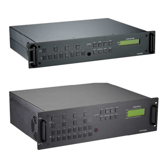
Support HDMI Type A for input and RJ-45 for output connectors. Beside it also supports a RS-232 or LAN communication port enables convenient communication with remote control equipment to switch the multimedia signals. Figure 1-1 HX-2384Z Figure 1-2 HX-331608Z... -
Page 10: Packing
1.2 Packing HDMI Matrix Switcher x 1 (HX-2384Z or HX-331608Z) Power Cord x 1 RS-232 Communication Connected Cable x 1 LAN Line x 1 IR Receiver Cable x 1 IR Blaster Cable x 1 Matrix Switcher Remote Controller x 1... -
Page 11: Accessories (Optional)
User Manual x 1 1.3 Accessories (Optional) IR Mini-Controller HDMI Remote Extender HDMI Cable *1... -
Page 12: Chapter 2 Features
CHAPTER 2 FEATURES Truly seamless, glitch-free switching between each input 8 HDMI Inputs with 4 HDBaseT Outputs for HX-2384Z, and 16 HDMI Inputs with 8 HDBaseT Outputs for HX-331608Z Any Input can be routed/broadcast to any Output Supports up to 70 meters zero compression extension via one single CATx cable Supports interlaced video to progressive video. -
Page 13: Chapter 3 Specifications
CHAPTER 3 SPECIFICATIONS Hardware HX-2384Z: HDMI Type A x 8 Input Connector HX-331608Z: HDMI Type A x 16 HX-2384Z: RJ-45 x 4 Output Connector HX-331608Z: RJ-45 x 8 RS-232 Connector DB9 Female LAN Connector RJ-45 RS-485 Connector 1 x 2 pins / 1 x 8 pins Dip Switcher 1 x 3.5 Jack... -
Page 14: Chapter 4 Installation
The Matrix Switcher has a black metallic housing. It can be placed on a sturdy desk directly or installed on a bracket (2U for HX-2384Z and 3U for HX-331608Z). You can also use the rubber feet pasted on the bottom of the chassis to protect your device when you want to place the device on a working desk. -
Page 15: Figure 4-3 Mount The Device In The Rack
Use the screws provided with the rack and a screw driver to firmly tighten the device in the rack to prevent working lose due to vibration on the rack. Figure 4-3 Mount the Device in the Rack... -
Page 16: Chapter 5 Front/Rear Panels
CHAPTER 5 FRONT/REAR PANELS 5.1 Front Panel HX-2384Z supports up to 8 Input and 4 Output switching keys on the Front Panel allowing you to switch signal quickly. Figure 5-1 HX-2384Z Front Panel HX-331608Z supports up to 16 Input and 8 Output switching keys on the Front Panel allowing you to switch signal quickly. -
Page 17: Figure 5-3 Aspect Ratio For Full Screen
The selected IN x key will transfer the input signal to all output channels. You can also press the “ALL” key and then press the “OFF” key to disable all the displayed switching settings. OFF: Disable the entire output channels. Press one of the OUT x keys that want to disabled for the output channel, then press the “OFF”... -
Page 18: Figure 5-4 Aspect Ratio For 1:1
Figure 5-4 Aspect Ratio for 1:1 INFO: This key can show you the ID, IP address and In/Out port information. Press this key to show you the connected ID and address. Press this key again to show you the status of all HDMI Type A or RJ-45 jacks on the rear panel. - Page 19 ACTIVE LED: A clear LED indicator designed for reaction by pressing keys on the front panel and remote controller. Refer to Appendix A Matrix Switcher Remote Controller IR Receiver: Infrared receiver can receive signals from the Matrix Switcher Remote Controller. LCD: LCD display shows current Matrix Switcher status and operation status.
-
Page 20: Rear Panel
5.2 Rear Panel HX-2384Z supports up to 8 input jacks (HDMI Type A) and 4 output jacks (RJ-45) on the rear panel, each female terminals form the signal input/output jacks. The HX-2384Z signal input/output terminal channels are numbered as IN1~8/OUT1, 3, 5, 7 channels. - Page 21 Appendix D RS-232 Communication Protocol for an individual configuration. RS-485: Connection ports allow you to connect/control more than one Matrix product, refer to 6.6.2 RS-485. RxGTx: Use the transmission line with RS-232 to connect the remote control PC for a data transmission between local and remote. Rx: Receive RS-232-level signal pin.
- Page 22 OUTPUT1, 3, 5, 7 or 9, 11, 13, 15: Matrix Switcher Output jacks are connected to extensible accessory devices (HX-SRW) for HDTVs, projectors or other sink devices connection. OUTPUT1, 3, 5, 7 or 9, 11, 13, 15 RJ-45 jacks are only used for extender (HX-SRW) connection.
-
Page 23: Chapter 6 Connections
Figure 6-1 HX-2384Z Connections Figure 6-2 HX-331608Z Connections The HX-2384Z/HX-331608Z supports individual independent modules I/O modules for reparation or upgrade. Each module can be configured individually based on module number. You can search these module numbers by pressing SETUP key when you want... -
Page 24: Input/Output Connections
Figure 6-3 Module Deployment 6.1 Input/Output Connections Use the HDMI connecting cable to connect the Input serial jack (No.1 ~ No.8 or 16) to the HDMI jack of the Blu-ray/DVD player/graphics workstations/number displays. Use the Cat.5e cable to connect the output RJ-45 jack (No.1, 3, 5, 7 or 9, 11, 13, 15) to the RJ-45 jack of extenders (HX-SRW). -
Page 25: Output Led
Figure 6-5 Output Connections 6.1.1 Output LED This Matrix Switcher supports HDBaseT output for a long distance signal transmission. Output connector is RJ-45 jack with two LED indicators. The LED indicators show you the status of output transmission. * The left LED of RJ-45 output jack is specified for HDCP (Yellow). * The right LED of RJ-45 output jack is specified for LINK (Green). -
Page 26: Output Cable
6.1.2 Output Cable HDBaseT was designed to provide Full HD performance up to 70 meters of Cat.5e or superior cables. In a typical installation, the cable is stretched to its full length between the HDBaseT Transmitter device and the HDBaseT Receiver device. However sometimes, especially, in demonstrations or in a lab environment, the cable is rolled randomly in small turns for convenience. -
Page 27: Ir Pass-Through Connection
6.2 IR Pass-Through Connection The Matrix Switcher provides an IR Receiver Cable and IR Blaster Cable accessories for IR pass-through. IR Receiver Cable can be connected to IR Rx ports or IR EXT on the rear panel. On the other hand, IR Blaster Cable can be connected to IR Tx ports on the rear panel. -
Page 28: Ir Ext Connection
6.3 IR EXT Connection The Matrix Switcher provides an IR Receiver Cable for more convenient to react to the Matrix Switcher Remote Controller. If it is difficult for you to aim at IR Receiver on the front panel due to the location of Matrix switcher, please connect IR Receiver Cable to the IR EXT port located on the rear panel for optional position. -
Page 29: Matrix Switcher Remote Control
6.5 Matrix Switcher Remote Control Use the RS-232 connecting cable to connect the computer serial communication port (COM1 or COM2) to the RS-232 communication port of the Matrix Switcher. The computer can then be used to control the Matrix Switcher after installing of application software. -
Page 30: Ports And Switchers
Matrix Switcher supports RS-232 and RS-485 on the rear panel for a remote control and allows you to operate settings via the keys located on the front panel. 6.6 Ports and Switchers The Matrix Switcher provides standard RS-232 and RS-485 serial communication ports. Beside the front panel for key switching operation, you can also use the RS-232 or RS-485 serial communication port to carry out remote operation. -
Page 31: Figure 6-12B Rs-232 - From Female Db9 (Pc) To Male Db9 (Matrix)
Figure 6-12b RS-232 – From Female DB9 (PC) to Male DB9 (Matrix) Figure 6-13 RS-232 – From Female DB25 (PC) to Male DB9 (Matrix) -
Page 32: Rs-485 (Matrix Connection)
Matrix Switcher. If the master device is specified for LAN, it allows you to control all the series devices with web browser. Remember all the ID of each device upon series connection has to be uniquely. Figure 6-14 RS-485 Connection for HX-2384Z... -
Page 33: Figure 6-15 Rs-485 Connection For Hx-331608Z
Figure 6-15 RS-485 Connection for HX-331608Z Figure 6-16 RS-485 Connection for HX-2384Z and HX-331608Z... -
Page 34: Rs-232 (Rxgtx Port)
See Pin definitions as below: RS-485 Figure 6-17 RS-485 Port Serial connection between Matrix RS-485: Pin1 TX(+) TX(+)--- Transmitted Data + Pin2 TX(-) TX(-)--- Transmitted Data - Pin3 Gnd (Ground) Pin4 RX(+) RX(+)--- Received Data + Pin5 RX(-) RX(-)--- Received Data - 1. -
Page 35: Lan Port
6.6.4 LAN Port This Matrix Switcher supports a network RJ-45 registered jack using 8P8C modular connector, which specifies the physical male and female connectors as well as the pin assignments of the wires in a telephone cable. (A common LAN cable is available.) Figure 6-19 RJ-45 Connector... -
Page 36: Dip Switcher 8 Pins
6.6.5 DIP Switcher 8 Pins Figure 6-20 DIP Switcher A. DIP Switcher Pin 1 to 5: Switch to down (ON) is specified for “0”, on the other hand to up (OFF) is specified for “1”. For Device ID settings refer to 6.6.7 Device ID Settings. -
Page 37: Dip Switcher 2 Pins
6.6.6 DIP Switcher 2 Pins Figure 6-21 RS-485 Terminal Switcher DIP Switch RS-485 Terminator: RS-485 Terminator for ON/OFF ON: RS-485 Terminator ON. OFF: RS-485 Terminator OFF. Proceed Multi Matrix Switcher connections, the RS-485 Terminator for the last device must be set to ON. Others must be set to OFF. 6.6.7 Device ID Settings Device ID Settings The Device ID determines the position of a Matrix system. - Page 38 ON/OFF Switching Positions ID Address ID Address Address (Decimal) (Hexadecimal) SW2 SW1 (Binary) 01011 01100 01101 01110 01111 10000 10001 10010 10011 10100 10101 10110 10111 11000 11001 11010 11011 11100 11101 11110 11111...
-
Page 39: Chapter 7 Matrix Application Software
CHAPTER 7 MATRIX APPLICATION SOFTWARE 7.1 Software Introduction The 《AV Matrix》 matrix control software applies to different input/output matrixes. To use the matrix function, the ID can not be set to 31 (ALL OFF). 7.1.1 Software Description The 《AV Matrix》 matrix testing software is an application tool developed for matrix testing and application. -
Page 40: Connect Matrix Switcher And Pc
7.1.3 Connect Matrix Switcher and PC You must power off the Matrix Switcher. Then, connect the Matrix RS-232 port to the PC RS-232 port with the bundled communication cable. And make sure the DIPs on the rear panel are set to Master and RS-232. (Refer to the previous section 6.6.1 RS-232) 7.2 Matrix Configuration... - Page 41 The Device ID is based on the DIP of switcher located on the rear panel. Slide the scrollbar on the lower left area of main window to view all contents (including ID, Name, A/V, I/O (only for VO/AO reference), Memory, VI Plug, AI Plug, VO Plug, AO Plug, EDID Type, Volume, Bass, Treble, Subwoofer, Delay, Delay Unit, Max Delay and Version) as described below: ID: Specify the ID address of Matrix Switcher.
-
Page 42: Main Operation Interface
Refer to the main window as above, the marked blue area shows crossing matrix of output ports 001, 003, 005 and 007 (HX-2384Z) or 001, 003, 005, 007, 009, 011, 013 and 015 (HX-331608Z) and input ports 001-008 (HX-2384Z) or 001-016 (HX-331608Z). You can slide the scrollbar on the INPUT/OUTPUT area to view all configured ports. - Page 43 Select all output: Click this button to select all output ports including output 001, 003, 005 and 007 (HX-2384Z) or 001, 003, 005, 007, 009, 011, 013 and 015 (HX-331608Z).
-
Page 44: Main Operation Interface
7.2.2 Main Operation Interface Disable all the unused output ports. A specific example of operation is described as below: The present input and output relations are shown in Figure 7-4a below: Figure 7-4a Disconnect Function Key for HX-331608Z Reference... -
Page 45: Figure 7-4B Disconnect Function Key For Hx-331608Z Reference
Follow the steps as below to disable the output ports including port 003 and 001. Step 1: First press down the output number keys 003 and 001 to the right of the blue configuration area. Step 2: Press the “Disconnect” key; Step 3: Press the previously pressed output number keys 003 and final 001 to complete the operation. -
Page 46: Edid Configuration Function
7.2.3 EDID Configuration Function Click “Video” tab to enter the video configuration window. In the video configuration window allows you to configure the EDID type of channel as FIX or Output1. In Matrix Switcher, the audio and video can be processed synchronously. Beside, all ports for EDID functions are also processed entirely. -
Page 47: Rs-232-Memory Function
7.2.4 RS-232-Memory Function Function Description: To store and retrieve the settings. Memory Save Function Description: The function saves all the present input/output switching relations to any Locations from #1 to #8 you desired. A specific example of the Save Function is described below: Store all the present input/output switching relations to Location #1. -
Page 48: Option Functions
7.2.5 Option Functions Activation Function: In the main configuration menu, select Options to prop-up the Options Window as left shown in Figure 7-11. Figure 7-8 Options 7.2.6 Other Application In the right main window displays the presently saved switching status as shown in Figure 7-12 below: Figure 7-9 Memory Configuration Status When input corresponding to Output is enabling, it shows the Output ports correspond to... -
Page 49: Chapter 8 Remote Configurations
5. Press Enter Please switch the DIP Switcher PIN 7 to UP and PIN 1-5 to DOWN for LAN configuration. The command examples for this chapter are for HX-2384Z reference. 8.1.1 Command List and Reboot Once the connection with Switcher is established, the Telnet prompt screen will appear, type help [Enter] to show the command list. -
Page 50: Ip/Telnet Configuration
Display the TCP/IP configuration HX-2384Z> ipconfig [Enter] Current IP: 192.168.0.3 Current IP Mask: 255.255.255.0 Current Gateway: 192.168.0.1 Renew the IP Address HX-2384Z> setip [ip addr] [Enter] [ip addr]: xxx.xxx.xxx.xxx Example: Set IP address: 192.168.0.2 HX-2384Z> setip 192.168.0.2 [Enter] HX-2384Z> setip IP address: 192.168.0.2 Renew the Subnet Mask HX-2384Z>... - Page 51 Example: Set gateway address: 192.168.0.1 HX-2384Z> setgateway 192.168.0.1 [Enter] HX-2384Z> setgateway Gateway: 192.168.0.1 Renew the DNS Servers HX-2384Z> setdns [ip addr] [Enter] [ip addr]: xxx.xxx.xxx.xxx Example: Set DNS IP address: 192.168.0.1 HX-2384Z> setdns 8.8.8.8 [Enter] HX-2384Z> setdns DNS IP:8.8.8.8 Set DHCP Enable or Disable HX-2384Z>...
-
Page 52: Device Configuration
Output 08: Input = 07 The output 2/4/6/8 is not useful that will show you a random value. Route configurations HX-2384Z> route [xx] [yy] [Enter] xx – select output port, 0: select all outputs yy – select input port, 0: disconnect Example: 1. - Page 53 2. Set all outputs to accept signals come from input 5. HX-2384Z> route 0 5 [Enter] or HX-2384Z>route 5 [Enter] Output 01: Input = 05 Output 02: Input = 01 Output 03: Input = 05 Output 04: Input = 03...
- Page 54 Input 01: EDID = 00 Input 02: EDID = 00 Input 03: EDID = 00 EDID management HX-2384Z> edid <edid> [Enter] <input>: select input port, 0: select all inputs <edid>: select edid source, 0: default 1080P, 1 copy port1 Example: HX-2384Z>...
-
Page 55: Av Matrix Protocol Command
8.1.4 AV Matrix Protocol Command Figure 8-4 AV Matrix Protocol Command Send AV Matrix protocol command <API> HX-2384Z> avm <instruction> <index> <value> [Enter] <instruction>: AVM Protocol Byte 2 <index>: AVM Protocol Byte 3 <value>: AVM Protocol Byte 4 Send OUTPUT Resolution HX-2384Z>... -
Page 56: Rs-232 Commands
8.2 RS-232 Commands You can also operate and configure the Switcher via a remote terminal session using RS-232. Follow the steps as below to log into the Switcher by means of a RS-232 session (the example as below is for Hyper Terminal): 1. -
Page 57: Commands List And Status
8.2.1 Commands List and Status Once the connection with Switcher is established, type help in the Hyper Terminal screen to show the command list. Show the command list Figure 8-5 Command List Show the Status of Your Switcher Figure 8-6 Switcher Status... -
Page 58: Hdmi Command
8.2.2 HDMI Command HDMI Output Setup Command Figure 8-7 HDMI Output Setup Command Example: Set output 1 signal comes from input 5. Figure 8-8 HDMI Output Setup Command - Example 8.2.3 EDID Command EDID Setup Command Figure 8-9 EDID Setup Command Example: Set resolution copied from EDID output 2. -
Page 59: Hdmi Output Resolution Commands
8.2.4 HDMI Output Resolution Commands Figure 8-11 HDMI Output Resolution Setup Command Example: Figure 8-12 Resolution Setup Command - Example 8.2.5 Restore Default Command Restore to Factory Default Settings Figure 8-13 Restore Default Command... -
Page 60: Chapter 9 Operation Examples
CHAPTER 9 OPERATION EXAMPLES Example 1: Switch the NO.1 input signal to the NO.3 output channel. LCD Display Operation HX-2384Z 1. Press the NO.3 key of the output channel, then the input channel will begin to flicker. HX-331608Z HX-2384Z 2. Press the NO.1 key of the Input channel. - Page 61 Example 2: Switch the NO.1 and NO.2 input signals to NO.1 and NO.3 output channels. LCD Display Operation HX-2384Z 1. Press the NO.1 key of the output channel, then the input channel will begin to flicker. HX-331608Z HX-2384Z 2. Press the NO.1 key of the Input channel.
- Page 62 LCD Display Operation HX-331608Z Example 3: “All” settings. LCD Display Operation HX-2384Z 1. Press the ALL key on the front panel, and then press the OFF key to cancel all the settings. HX-331608Z 2a. Press ALL key then select HX-2384Z input 8 that indicate all outputs will switch to selected inputs.
- Page 63 Example 4: “STO” and “RCL” functions. LCD Display Operation HX-2384Z 1. Press the STO key on the front panel. The Store to Memory begins to flicker about 8 seconds. HX-331608Z HX-2384Z 2. Press the IN1 key or OUT1 key to save the setting in the NO.1 memory location.
- Page 64 4. Press the IN1 key or OUT1 HX-2384Z key to Load the previously saving. HX-341608Z Example 5: “STO” and “RCL” combinations – restore to factory default values. LCD Display Operation HX-2384Z 1. Press and hold the STO and RCL keys about 2~3 seconds...
- Page 65 IN4: 1280x720P 60HZ IN5: 1280x1024 60HZ IN6: 1600x1200 60HZ IN7: 1920x108P 60HZ IN8: 1920x108P 50HZ LCD Display Operation HX-2384Z 1. Press the NO.1 key of the output channel, then the input channel will begin to flicker. HX-331608Z HX-2384Z 2. Press the NO.5 key of the Input channel.
- Page 66 Example 7: “SETUP” function. Set the NO.1 output to 1:1 aspect ratio. IN1: 1:1 aspect ratio IN2: Full screen ratio LCD Display Operation HX-2384Z 1. Press the NO.1 key of the output channel, then the input channel will begin to flicker.
- Page 67 Example 8: “EDID” functions. LCD Display Operation HX-2384Z Press the EDID key to switch FIX and OUT1, refer to EDID. HX-331608Z Example 9: “INFO” function. LCD Display Operation HX-2384Z Press the INFO key to show you the device and I/O jack information.
- Page 68 Example 10: “SETUP” and “INFO” combinations. LCD Display Operation HX-2384Z 1. Press the SETUP and INFO keys simultaneously on the front panel. The screen will show you the firmware version HX-331608Z of module. (The version value is only for reference.) 2.
-
Page 69: Chapter 10 Troubleshooting
CHAPTER 10 TROUBLESHOOTING 1. What to do if LCD is fail in display? Answer: Check the connection of power cord is not loosening and the power cord is in a good status having no any damage. Check the power source is normally. 2. - Page 70 5. What to do if you sense the power leakage during plugging or unplugging of the input/output ports? Answer: It could be that the equipment power is not properly grounded. You must properly ground your equipment; otherwise product life can easily be shortened. 6.
-
Page 71: Appendix Amatrix Switcher Remote Controller
APPENDIX MATRIX SWITCHER REMOTE CONTROLLER The Matrix Switcher supports a remote control interface allows you to control the channels and video features switch of Matrix Switcher through remote controller. Figure A-1 Matrix Switcher Remote Controller OSD, SCAN, , AUDIO, VIDEO and +10 keys are useless. ID key is the same as “INFO”... -
Page 72: Appendix B Ir Mini-Controller
APPENDIX B IR MINI-CONTROLLER The Matrix Switcher supports an IR Mini-Controller to allow you to select input channel through infrared sensor upon an extended connection – Extender (HX-SRW). The signal for IR Mini-Controller is only available to the IR Receiver Cable connected to the IR1 IN or IR2 IN IR receiver of Extender (HX-SRW). -
Page 73: Appendix C Firmware Upgrade
APPENDIX C FIRMWARE UPGRADE This Chapter will introduce you how to upgrade firmware on your web browser. For firmware upgrade, you have to upload the firmware file to your web server and then upload it to your device from web server. Follow the steps as below to upgrade the firmware: 1. -
Page 74: Figure C-3 Upload Status Message
3. After clicking “Upgrade”, the upload message screen as below will appear. Click “OK” to continue. Figure C-3 Upload Status Message 4. Select “0: General” form the drop-down list and click “Upgrade” to upload the firmware to your device. Figure C-4 Update Switcher’s Firmware... -
Page 75: Figure C-5 Update Switcher's Firmware
5. Select “1: Matrix I/O Module” will allow you to upgrade I/O modules. You have to decide which device you want to configure, and then select the suitable Device ID and I/O Module from the drop-down menu. Click “Update” to upgrade. Figure C-5 Update Switcher’s Firmware The Matrix Switcher supports modules for upgrading;... -
Page 76: Figure C-7 Update Switcher's Firmware
Besides, the firmware upgrade will not stop even though the web connection is fail suddenly. Please check with the LCD screen to confirm the firmware upgrade has been finished successfully or wait at least 2 minutes then power off to restart your 7. -
Page 77: Appendix D Rs-232 Communication Protocol
APPENDIX D RS-232 COMMUNICATION PROTOCOL This AV Matrix RS-232 communication protocol uses fixed length with 5 bytes of information as define below. The default baud rate is 9600 bps, no parity, 8 data bit and 1 stop bit. Command timeout is 300 milliseconds, and byte to byte timeout is 30 ms. Use the RS-232 connecting cable to connect the computer serial port to the RS-232 communication port of the Matrix Switcher. -
Page 78: D-1.2 Request Byte
0x07 Request Video Output Channel Output Memory 0x08 Request Audio Output Channel Output Memory Plug Detect (Not Applicable in HX-2384Z/331608Z) 0x09 Request Video Input Plug Status Input 0x0A Request Audio Input Plug Status Input 0x0B Request Video Output Plug Status... - Page 79 0x16 Control Audio Output Treble Output Level 0x17 Request Audio Output Treble Output Memory 0x18 Control Audio Output Subwoofer Output Level 0x19 Request Audio Output Subwoofer Output Memory 0x1C Control Audio Output Delay Low Output Delay1 0X1D Request Audio Output Delay Low Output Memory 0X1E...
-
Page 80: D-1.3 Index Byte
D-1.3 Index Byte Index Byte (IB) Name Bit 7 Bit 6 Bit 5 Bit 4 Bit 3 Bit 2 Bit 1 Bit 0 Index Index: Please refer to "Table - Host Request List" and "Table - Command Index List". Table – Command Index List Index Description The output that will be selected. -
Page 81: D-1.4 Value Byte
D-1.4 Value Byte Value Byte (VB) Name Bit 7 Bit 6 Bit 5 Bit 4 Bit 3 Bit 2 Bit 1 Bit 0 Value Value: Please refer to "Table - Host Request List" and "Table - Command Value List". Table – Command Value List Value Description The input that will be connected. -
Page 82: D-1.5 Byte 5 - Check Byte
D-1.5 Byte 5 – Check Byte Check Byte (CB) Name Bit 7 Bit 6 Bit 5 Bit 4 Bit 3 Bit 2 Bit 1 Bit 0 CRC (cyclic redundancy check) CRC: Host must send CRC code to follow the last byte. Example: 20 01 05 03 93 --- Device ID 0, Switch Video Output 6 to the Input 3. - Page 83 Example: BYTE BIT 7 6 5 4 3 2 1 0 0x23 0 0 1 0 0 0 1 1 0x01 0 0 0 0 0 0 0 1 ------------------------------------------------------------------ A ^ B 0x22 0 0 1 0 0 0 1 0 A ^ B = 0x23 ^ 0x01 = 0x22 CRC calculation for C Language command[0] = 0x20;...
-
Page 84: Device Ack Packet
D-2 Device ACK Packet When the device receives supported commands comes from the host, and then will response with following ACK: Table – ACK Type List Ack Type Byte 1 Byte 2 Byte 3 Byte 4 Byte 5 Byte 6 Last Byte Type A Type B... -
Page 85: D-2.2 Ack Type B
D-2.2 ACK Type B ACK Byte + LB + Index1 + Value1 + Index2 + Value2 +O..+ CRC Byte Name Bit 7 Bit 6 Bit 5 Bit 4 Bit 3 Bit 2 Bit 1 Bit 0 Device ID (0 – 31) Length for the total data bytes (Index + Value) IB n Index... -
Page 86: D-2.3 Ack Type C
D-2.3 ACK Type C ACK Byte + LB + Data 1 + Data 2 + CRC Byte (Total 5 Bytes) Name Bit 7 Bit 6 Bit 5 Bit 4 Bit 3 Bit 2 Bit 1 Bit 0 Device ID (0 – 31) Length for the total data bytes (This byte is always 2) DB 1 Data 1... -
Page 87: D-2.4 Ack Type D
D-2.4 ACK Type D ACK Byte + LB + INF + OP + IP + Name 1 + Name 2 + Name 3 +..+ CRC Byte Name Bit 7 Bit 6 Bit 5 Bit 4 Bit 3 Bit 2 Bit 1 Bit 0 Device ID (0 - 31) Length for the total data bytes (INFO +..+ Name n) -
Page 88: D-2.5 Ack Type E
D-2.5 ACK Type E ACK Byte + LB + EXTI + VIDI + AUDI + PLUG +..+ CRC Byte Name Bit 7 Bit 6 Bit 5 Bit 4 Bit 3 Bit 2 Bit 1 Bit 0 Device ID (0 - 31) Length for the total data bytes (EXINF +..+ DTMAX) LBMAX EXINF... - Page 89 AOPD - Audio output plug detection command flag. (Request 0x0C) 1 - Support Audio output plug detection. 0 - Not support Audio output plug detection. Others - Bit 7~4 are reserve, always 0 PLUG is not applicable in HX-2384Z/331608Z. DTMAX: defines audio maximum delay time. (Unit: 100 ms)
-
Page 90: Appendix E Extender (Hx-Srw)
APPENDIX E EXTENDER (HX-SRW) The extension of HDMI video signal device supports up to 70 meters away by using an Extender and Cat.5e cable. HDMI Extender is ideal for: Test bench facilities Data Center Help desks Front View Rear View Figure E-1 HDMI Extender Panel Views LED Indicators (Green): Blink... -
Page 91: Features
E-1 Features Through the Extender (HX-SRW), you can use the output of HX-2384Z or HX-331608Z to display identical image and extension of HDMI signal up to 70 meter on HDTV HDCP Compliant Support 3D pass-through Support all frequency band IR pass-through One Cat.5e cable extension... -
Page 92: Ir Receiver Cable Directions
E-4 IR Receiver Cable Directions Put IR Receiver Cable into the Extender (HX-SRW) “IR2 IN” port and place the IR Receiver Cable, so that you can point to it easily with your IR remote controller. IR Receiver Cable: Figure E-2 IR Receiver Cable E-5 IR Blaster Cable Directions Plug IR Blaster Cable into Extender (HX-SRW) “IR OUT”... -
Page 93: Wiring Information For Link Connector
E-7 Wiring Information for Link Connector Figure E-5 Wiring Information for Link Connector Conductor Identification RJ-45 Pin Assignment Color Code for Conductor White-Blue Pair 1 Blue White-Orange Pair 2 Orange White-Green Pair 3 Green White-Brown Pair 4 Brown However sometimes, especially in demonstrations or in a lab environment, the cable is rolled randomly in small turns for convenience. -
Page 94: Firmware Upgrade
E-8 Firmware Upgrade Before upgrading firmware, you have to receive a Firmware burn package containing all software needed for burning. Follow the steps as below to upgrade the Extender (HX-SRW) firmware: 1. Connect the power cord to the power port on the panel of Extender (HX-SRW). The other end of the power cord connected to a suitable power source. -
Page 95: Z / / H Hx
5. The burning windows will pop-up and begin to upgrade. Figure E-9 Update Extender’s Firmware 6. Final, the burning is finish as below. Figure E-10 Update Extender’s Firmware...
Need help?
Do you have a question about the HX-2384Z and is the answer not in the manual?
Questions and answers