Table of Contents
Advertisement
Quick Links
6LPRQ 6HFXULW\
6\VWHP &RQWURO
3DQHO
Document Number: 466-1873 Rev. C PRELIMINARY
May 2002
Contents
Installation Instructions
Programming 10
ITI Part Nos. 60-875
60-910
Doors &
Motion
Windows
Sensors
Status
H O M E S E C U R I T Y
Arm
Disarm
System
1 / 2
3 / 4
5 / 6
7 / 8
9 / 0
C O D E
Special
Doors
Motion
Time
Sensor
On
Off
H O M E C O N T R O L
Chime
Lights
E M E R G E N C Y
FIRE
POLICE
AUX
Test Weekly
Advertisement
Table of Contents

Related Manuals for Simon 3


Summary of Contents for Simon 3
-
Page 1: Table Of Contents
Option 03: Latchkey 13 System Devices 3 Option 04: Primary Phone Number 13 Option 05: Secondary Phone Number 13 Planning Sensor Types & Locations 3 Option 06: Downloader Phone Number 14 Option 07: Account Number 14 Device Locations 4 Option 08: Phone Lock 14... - Page 2 Phone Number 20 Sensors 32 Option 44: Numeric Pager/Voice Event Notification X-10 Modules 32 Phone Mod 3 20 Option 45: Sensor Alarm Restoral Report 21 Appendix B: System Configuration 33 Option 46: Fire Shutdown - AVM 21 Option 47: AVM Mode 21...
-
Page 3: Fcc Notices
REN for this product is part of the product identifier that has the format US:AAAEQ##TXXXX. The digits represented by ## are the REN without a decimal point (e.g., 03 is a REN of 0.3). For earlier products, the REN is separately shown on the label. - Page 4 Canada Notice The Canadian Department of Communications label identifies certified equipment. This certification means that the equipment meets certain telecommuni- cations network protective, operational, and safety requirements. The department does not guarantee the equipment will operate to the user’s satisfaction. Before installing this equipment, users should ensure that it is permissible to be connected to the facilities of the local telecommunications company.
-
Page 5: About This Manual
About This Manual About This Manual Option 26: Fail to Communicate set to on Option 29: Control Panel Alarms set to on Option 39: Siren Timeout set to 4 minutes or more This manual provides information for planning, installing, pro- Option 40: Trouble Beeps set to on gramming, and testing this security system. -
Page 6: California State Fire Marshall Listed Installations
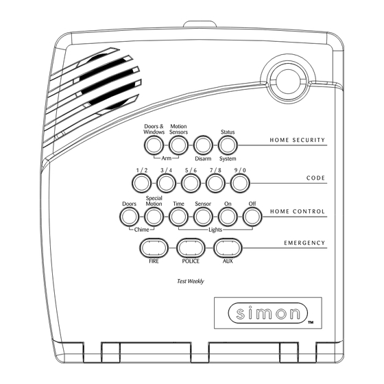
S E C U R I T Y A r m D i s a r m 1 / 2 3 / 4 5 / 6 7 / 8 9 / 0 S p e c i a l... -
Page 7: System Devices
Planning Sensor Types & Locations System Devices Keychain Touchpad* (60-659) The Keychain Touchpad lets you turn the system on and off from right outside the home or activate a panic alarm if there is The system can monitor up to 24 sensors and may use any of an emergency. -
Page 8: Device Locations
Planning Sensor Types & Locations Note All Lamp Modules with the same house code will turn on or flash as a group during an alarm or when operating the Recommended Sensor Types “Light” button on a Keychain Touchpad. The numbered dial sets the unit number, which identifies and Device Recommended lets you control a specific device. -
Page 9: Installing The System
(GFIC). Refer to Figure 3 for mounting hole locations. For wall mounting, hold the panel against the wall and mark the mounting hole locations with a pencil. For... -
Page 10: Connecting Hardwire Devices
D C O U T H W I N 1 Connecting Hardwire Devices The panel has 5 screw terminals located on the upper-right cor- ner of the circuit board (see Figure 3) for connecting AC power, sirens and/or hardwire detectors. AC Terminals BLACK Note All inputs and outputs are Class II power limited circuits. -
Page 11: Wiring Exterior Sirens
HWIN1 and/or HWIN2. Other types of hardwire detectors ming” section). should not be used. The total resistance of the wire loop must not exceed 3 ohms. Hardwire Exterior Siren with Supervision This allows you to use up to 200 feet of 2-conductor, 22-gauge stranded wire. -
Page 12: No Line Seizure
Installing the System Full Line Seizure Wiring with an RJ-31X Full Line Seizure Wiring with 1 Premises Phone Note If a single phone is all that exists on the premises, full line sei- For UL Listed systems, the RJ-31X jack must be zure can be accomplished without an RJ-31X. -
Page 13: Wiring The Power Transformer
Installing the System Wiring the Power Transformer Connect the red and black battery leads (included with panel) to the battery and panel terminals (see Figure Connect the power transformer to the panel AC terminals as 12). shown in Figure 10. Note Do not plug in the transformer at this time. -
Page 14: Universal Module
Programming Set the house code for the installation. Set House Code and Light & Appliance Controls (Entry/Exit activated lights, Sensor activated lights, Plug the module into a wall outlet. Time activated lights). Plug the lamp/appliance into the module. Change numbered Options as needed. CAUTION! Do not plug in appliances or lamps with 300-watt or Exiting Program Mode... - Page 15 When adding (learning) sensors, the panel uses an ascending numbering sequence starting with 1. You can override this by entering the desired sensor number using the numbered keys. START MENU Version 3 Delete Cancel Test System should be checked...
-
Page 16: Deleting Sensors
Programming Deleting Sensors To add a time-activated module: Press Add . Press Light Control. To delete sensors: Press Unit # until you hear the unit number that matches the one you chose on the module. Press Delete . The panel announces “Select from Main Press Time. -
Page 17: Option 01: Panel Piezo Beeps
10 seconds. Silent Exit—3 beeps sound at the To set Latchkey, press: beginning of the exit delay and 3 more Add—Option #—03—Hours—Minutes—DONE. sound just before the exit delay expires. Entry Delay—3 beeps sound every 5 To turn off Latchkey, press: seconds and 3 times per second during Delete—Option #—03—DONE. -
Page 18: Option 06: Downloader Phone Number
When turned on, the Entry Delay can be set from 005-254 sec- onds (030-254 if SIA Limits Option 69 is on). All entries must be 3 digits. When turned off, the Entry Delay is set to 005 sec- Lets you program up to a 10-character alphanumeric account onds (030 if Option 69: SIA Limits is on). -
Page 19: Option 12: Phone Mod 1
All entries must be 2 digits. onds (045-254 if SIA Limits Option 69 is on). All entries must be 3 digits. When turned off, the Exit Delay is set to 005 sec- Phone Mod 2 onds (045 if Option 69: SIA Limits is on). -
Page 20: Option 16: Auto Phone Test
Determines whether the panel automatically performs a peri- The time can be set from 005 - 255 minutes. Entries must be 3 odic phone test (on) or not (off). digits. When set to 255, the panel always reports alarm cancel messages. -
Page 21: Option 21: Opening Reports
AC power restoral when AC power returns to the Disabled—no remote (off-site) access panel. The time can be set from 5-254 minutes. Entries must be 3 dig- For off-site access where an answering machine does not exist, its. -
Page 22: Option 28: No Delay From Keychain Touchpad
(on), or not (off). If set to 2, perform steps 1 - 3 twice. To turn on Downloader Enable, press: If set to 3, perform steps 1 - 3 three times. Add—Option #—31—DONE. To turn on Ring/Hang/Ring, press: To turn off Downloader Enable, press: Add—Option #—27—1, 2, 3, or 4—DONE. -
Page 23: Option 35: Fail To Close Report
The time can be set from 002 - 254 minutes. Entries must be 3 digits. When this feature is turned off, sirens sound alarms until Note System time must be set correctly for this feature to work. -
Page 24: Option 40: Trouble Beeps
(off). AC power failure When used to call a numeric pager, a 3-digit code appears on Low CPU battery the pager display to identify the report. When used to call a remote phone, a person at the remote phone location can hear Sensor failure (supervisory) system voice alarm announcements. -
Page 25: Option 45: Sensor Alarm Restoral Report
Delete—Option #—48—DONE. To turn on Sensor Alarm Restoral Report, press: Option 49: Arming LEDs Shutdown (Default = off) Add—Option #—45—1, 2, or 3—DONE. To turn off Sensor Alarm Restoral Report, press: Determines whether the panel LEDs (buttons) turn off 30 sec- Delete—Option #—45—DONE. -
Page 26: Option 52: Unvacated Premises
Utility 1—321 Note This feature does work from a keychain touchpad. Utility 2—321 If this option is turned on and the user arms to level 3 (ARM Master—1234 Motion Sensors) or 4 (ARM Doors & Windows, + ARM Utility 1—4321 Motion Sensors) but does not exit the premises within the Exit Delay time, the panel automatically changes to arming level 2. -
Page 27: Option 57: Supervisory/Tamper Report
Programming Option 60: Secure Arming (Default = off) To program Call Waiting, press: Add—Option #—56—Up to 26 digits—DONE. Note Determines whether an access code is required when arming Pressing DONE is required if you enter fewer than 26 the system (on) or not (off). digits. -
Page 28: Option 64: No Arm On Panel Low Battery
Option 69: SIA Limits (Default = on)* customer. The time can be set from 001 to 254 days. Entries must be 3 Determines whether Entry, Exit, and Dialer delay times fall digits. -
Page 29: Option 70: Not Available
Programming Option 70: Not Available To turn off Silent Panel Police Panic, press: Delete—Option #—74—DONE. Option 71: Programming Report (Default = off) Option 75: VOX Mic Gain (Default = 14) Determines whether the panel sends a report to the central sta- Sets the mic gain (sensitivity) that triggers the voice-activated tion anytime the programming mode is entered/exited (on) or switching (VOX). -
Page 30: Option 78: Vox Receiver Gain
1-5, program the panic code, per- form a sensor or phone test, and program options 1, 2, 3, 31, 36, 37, 41, 42, 43, and 55. -
Page 31: Sensors
8 times sensors are armed. SYSTEM STATUS-Press to determine system status and Glass Guard Tap the glass 3 or 4 inches from the system time. sensor CHIME Doors-Press to enable two beeps that sound from... -
Page 32: Improving Sensor/Panel Communication
Phone Test is OK Do not do this for installations that require antenna within 3 minutes. The panel will say Phone test is on tamper for external antennas. three times if you have a pager. Your pager will display 101 101 if the phone test to the pager was successful. -
Page 33: Off-Site Phone Operation
Call the central station and tell the operator that you audio session. will be testing the system. Press 1 or 0 to speak, 2 for VOX operation, and 3 or 6 Arm the system. to listen. Test each of the wireless panic buttons and trip at least Press 99 to terminate the session. -
Page 34: Voice Event Notification
If an alarm of greater priority occurs during an alarm of lower priority, the greater priority alarm sirens sound. Fire alarms sound a temporal 3 pattern (0.5 seconds on, 0.5 seconds off for Voice Event Notification three beeps then 1.5 seconds off). -
Page 35: Emergency Planning
Emergency Planning Emergency Planning Emergency Planning Floor Plan Use the following guidelines when drawing an emergency floor plan for the homeowner: Show all building levels. Show exits from each room (2 exits per room are recom- mended). Show the locations of all security system components. Show the locations of any fire extinguishers. -
Page 36: Appendix A: Troubleshooting
Time or sensor activated light not working. Latchkey does not function. Make sure you have programmed the light to be activated Latchkey time (option 3) is not set. Set Latchkey time. by a timer or sensor. Latchkey is not enabled. Enable Latchkey by pressing Make sure the system clock is set. -
Page 37: Appendix B: System Configuration
Appendix B: System Configuration Appendix B: System Configuration Sensor Assignments/Locations Sensor Sensor Name/Location Notes Sensor Device Group Alphabetical Listing of Sensor Names Attic, Back Door, Back Window, Basement, Basement Win- dow, Bathroom, Bathroom Window, Bedroom, Bedroom Win- dow, Child’s Room, Child’s Room Window, Closet, Den, Den Window, Dining Room, Dining Room Window, Downstairs, Downstairs Window, Front Door, Front Window, Garage, Garage Door, Garage Window, Guest Room, Guest Room... -
Page 38: Sensor Group Characteristics
Appendix B: System Configuration Sensor Group Characteristics Active Name/Application Siren Type Levels 00 Fixed Panic: 24 hour audible fixed emergency button Intrusion 1234 01 Portable Panic: 24 hour audible portable emergency buttons Intrusion 1234 02 Fixed Panic: 24 hour silent fixed emergency buttons. Status light will not blink. Silent 01234 03 Portable Panic: 24 hour silent portable emergency buttons. -
Page 39: Home Control Planning
Utility Access Code 2 654321, 54321, 4321, or Master Access Code 123456, 12345, 1234, or Access Code 1 None Access Code 2 None Access Code 3 None Access Code 4 None Access Code 5 None Panic Code None Option Settings... - Page 40 Appendix B: System Configuration Function Default Delete Range Who Can Installer Change: Settings Panel Piezo Beeps On/Off U1 U2 M (must be on for UL listed systems) Panel Voice On/Off U1 U2 M Latchkey Option 12:00 Midnight - U1 U2 M 11:59 PM Primary Phone Number None...
- Page 41 Chime Voice On/Off U1 U2 M Speaker Level U1 U2 M Pager Phone Number 26 digits U1 U2 M Pager Phone Mod 3 08-10 U1 U2 Sensor Alarm Restoral Off (0) Off (0) 0 - 3 U1 U2 Fire Shutdown - AVM...
- Page 42 Appendix B: System Configuration Function Default Delete Range Who Can Installer Change: Settings Programming Report On/Off U1 U2 Supervisory Time Midnight U1 U2 Modem Sensitivity On (high)/Off U1 U2 (normal) (normal) Panel Police Panic Audio On (silent)/Off U1 U2 (audible (audible) VOX Mic Gain 1-64...
-
Page 43: Specifications
Specifications Specifications Power Requirements: ..9 VAC, 700 mA Rechargeable Batteries: 6.0 VDC, 1.2 Ah Lead-Acid The battery will last 24 hours with no AC and specified standby load Radio Frequency: ....319.5 MHz (60-875) 433 MHz (60-910) Nominal Range: ....500 feet, open-air receiving range Storage Temperature Range:-29°... -
Page 44: Quick Reference Table
Doors & Motion Press * + Master each Windows & Windows Sensors Press twice button Code + 2 + 3 Motion Sensors Press each button once once Doors & Windows Activate No Entry Press once (if Press twice Press * + Master Press twice Doors &...
Need help?
Do you have a question about the 3 and is the answer not in the manual?
Questions and answers