Table of Contents
Advertisement
Quick Links
Advertisement
Table of Contents

Related Manuals for HEX HERE+

Summary of Contents for HEX HERE+
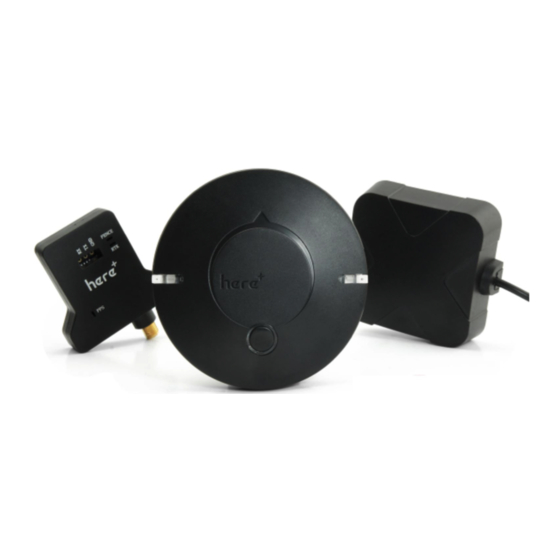
- Page 1 HERE+ GNSS USER GUIDE V1.0 Aug 2017...
-
Page 2: Table Of Contents
Content 1) Upgrading to U-blox 1.30 Firmware ......3 Downloading U-centre UI and 1.30 Firmware ..............3 Connect your HERE+ Base and Rover to Computer ............4 Upgrading Process ......................5 Check current Rover/Base firmware version ..............8 2) Basic Operating Manual ........... 9 Use Mission Planner for Base module surveying/ Rover module positioning ...... -
Page 3: Upgrading To U-Blox 1.30 Firmware
1) Upgrading to U-blox 1.30 Firmware The default firmware version of the HERE + modules is ublox-1.10 firmware. The new version of 1.30 firmware includes new feature of fusing other satellite systems (Glonass / beidou) with GPS for RTK operations, effectively increasing the RTK positioning accuracy. Therefore, it is recommended that all users upgrade to 1.30 firmware before using HERE+. -
Page 4: B) Connect Your Here+ Base And Rover To Computer
b) Connect your HERE+ Base and Rover to Computer When upgrading the base station module, use the USB cable to connect the base station module to the computer USB interface, as shown in the following figure: When upgrading a Rover module, use a hexagonal screwdriver to open the case. The rover module has a USB interface connector identical to the base module, you can use the base module USB cable to connect rover to computer. -
Page 5: C) Upgrading Process
c) Upgrading Process Open the U-center software, click the connection button (as shown in the red circle), select the com port that corresponds to your base/ rover module. Click tools->u-blox 5 – 8 Flash Firmware Update, and click the settings as shown below:... - Page 6 In Firmware image, unzip and select the downloaded 1.30 Firmware. For base module, chose the firmware with title: UBX_M8_301_HPG_130_REFERENCE_NEOM8P2.59a07babb501ba6a89ff87cac2f 2765f.bin For rover module, choose the firmware: UBX_M8_301_HPG_130_ROVER_NEOM8P0.3ee86a9e4775e3335e742b53527fa5 d0.bin In Flash Information Structure(FIS) File, select Flash.xml,which is located in the installation address of U-centre software.
- Page 7 Click OK and wait for the firmware uploading to complete. Uploading usually takes only a minute or less. If the uploading is successful, the upgrade interface is displayed in green; if the upgrade is aborted, the interface is displayed in red. If the process is interrupted, or if it is not responding for a long time, the modules will need to be power cycled and uploading needs to be done again.
-
Page 8: D) Check Current Rover/Base Firmware Version
d) Check current Rover/Base firmware version When base/rover is already connected to U-centre, click View, go to Message View -> UBX -> MON -> VER, you will see the interface below: As shown in the figure, the current firmware version is FWVER = HPG 1.30 REF, indicating that the current firmware version is 1.30 for base module. -
Page 9: Basic Operating Manual
2) Basic Operating Manual a) Use Mission Planner for Base module surveying/ Rover module positioning This part of the tutorial uses Mission Planner ground control software and Arducopter-3.5 flight control firmware for operating instructions. If you are using PX4 firmware and QGroundControl ground station software, please refer to the link: 。... - Page 10 During operation, please place the base station in an outdoor environment with sufficient sky coverage to obtain a good satellite signal. Place the base station on a stable and elevated platform, such as a tripod.
-
Page 11: Ii) Base Module Setting Using Mission Planner
ii) Base Module setting using Mission Planner Start with base module setup first. During the base station setup, the rover and the UAV do not need to be turned on. Open the Mission Planner ground station software on your computer and go to the initial setup ->... - Page 12 During the survey process, the right box will show the current survey status: Position is invalid: base station has not yet reached a valid location; In Progress: survey is still in progress; Duration: The number of seconds that the current surveying task has been executed; Observation: the number of observations acquired;...
- Page 13 After the survey is complete, Mission Planner will display the following page: In the RTCM box is shows that the base status indicator is green and both the GPS and Glonass satellite systems are green (if you want to change the satellite system, refer to the following section).
-
Page 14: Iii) Rover Module And Flight Controller Setup
iii) Rover Module and Flight Controller Setup After the base station is set up, you can turn on the UAV. Using the same Mission Planner to connect the telemetry module, the base station data will be transmitted through telemetry module to the HERE + rover module on the UAV. In the Mission Planner main page, you can see the current GPS status displayed as RTK Float / RTK Fixed / 3D RTK, indicating that the positioning of the UAV has entered the RTK mode. -
Page 15: B) Use U-Centre For Live Data Recording/Replaying
b) Use U-centre for live data recording/replaying One function of the U-center is to record the base / rover module data for later analysis. Firstly, when the base or rover module is already connected to U-center (in the same way it is connected when updating firmware), click the following bug icon to turn on the debug message: Then, click into View ->... -
Page 16: A) Check Status Of Base Station
3) Use U-Centre for debugging/advanced configuration a) Check Status of Base Station Connect the base module to U-center software, check the display box in the upper right corner of the interface, Fix Mode section is displayed as TIME. If Fix Mode does not enter TIME, the current state of the base station is not sufficient to allow the rover module to enter RTK mode. -
Page 17: B) Check Whether Rover Receives Base Correction Data(Timeout)
Secondly, the user input of survey-in accuracy requirement is too strict to achieve, or the base station has not yet completed the surveying process. Using U-centre for survey-in setup, please refer to section c) in this chapter. b) Check whether Rover receives base correction data(Timeout) After the base station enters the TIME Mode, it is necessary to transmit the RTCM data to the rover, for rover to enter RTK modes. -
Page 18: D) Use Beidou/Glonass
The base station can also be set to Fixed Mode. When the base station's current precise geographic coordinates are known, the coordinates can be entered directly into the base station, which saves the time required for surveying. In the TMODE3 page, select Fixed mode in the drop-down list, and then enter the precise known base station coordinates. -
Page 19: E) Base Module I/O Port And Protocol Setup
To save the current settings, go to the Messages view -> UBX -> CFG (Configuration) page and click the Save current configuration option, then click Send (as shown below). Note: Base station and rover should use the same navigation system configuration, or rover will not be able to enter RTK modes. -
Page 20: F) Change Rover Module Output Rate
CFG -> PRT directory and select 3-USB in the Target field. The correct input and output protocols are shown below: If you want to use more output protocols (such as UART), you can also select the output protocol and a specific message combination on this page. If you want to set a string of specific messages to output under a variety of protocols, you can go to the Messages view ->... -
Page 21: Change Base Antenna And Testing
To save the current settings, go to the Messages view -> UBX -> CFG (Configuration) page and click the Save current configuration option, then click Send. 4) Change Base Antenna and Testing HERE + base module antenna is a Taoglass antenna. Users can select different antennas according to their needs and connect them to base module. - Page 22 Test Antenna A: Test Antenna B: Original Antenna:...
- Page 23 Base status with Antenna A at TIME Mode: Base status with Antenna B at TIME Mode: Base status with original antenna at TIME Mode:...
- Page 24 Satellite signal comparison for each satellite: Satellite Comparison Across Antenna G1 G3 G7 G8 G9 G11 G17 G19 G22 G28 G30 B1 B2 B3 B4 B5 B6 B7 B8 B9 B10 B13 B17 Antenna A Antenna B Taoglass Number of satellites reception above 40 with antenna A: 12 satellites Number of satellites reception above 40 with antenna B: 13 satellites Number of satellites reception above 40 with original antenna: 14 satellites...
Need help?
Do you have a question about the HERE+ and is the answer not in the manual?
Questions and answers