
Subscribe to Our Youtube Channel
Related Manuals for Hydro Mobile M2 Series

Summary of Contents for Hydro Mobile M2 Series
- Page 1 Owner’s Manual Call us for information: 1-888-484-9376 (US) (toll free in the United States) 450 589-8100 (Canada) 11053005-0-00000-0 M2_OpMan_v5.02_EN...
- Page 2 Assembly or operation instructions displayed on the motorized unit Owner's manual Any use of one or several Hydro Mobile motorized units, with or without accessories, in such a confi guration or manner as not explicitly described in this manual is not allowed without the permission of Hydro Mobile Inc.
-
Page 3: Table Of Contents
ENERAL NFORMATION TABLE OF CONTENTS General Information General Information 5 – Masts and Mast Ties 5 – Masts and Mast Ties Introduction ..............3 Installation of a mast section ........69 Warranty ..............4 Installation of mast ties ..........70 Mast tie schedule ..........70 Performance and Safety Performance and Safety Appropriate mast tie installation......71... -
Page 4: Introduction
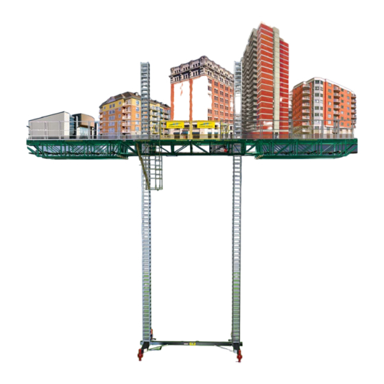
Introduction Dear owner or user: Thank you for investing in a Hydro Mobile M2 Series mast climbing work platform system (24' / 7,3 m model or 14' / 4,3 m model). The design of these motorized units refl ects over a decade of continued fi... -
Page 5: Warranty
Hydro Mobile also warrants its new M2 Series parts and accessories to be free from defect of materials and workmanship for a period of 15 months from the date of delivery to the authorized distributor/service center. -
Page 6: Performance And Safety
Only a qualifi ed person on the specifi c make and model of the Hydro Mobile equipment can carry out the following tasks: User/operator A qualifi... - Page 7 In all cases where workers are exposed to fall hazards, fall protection is required. Installation of all the necessary guardrails is mandatory. 18- The M2 Series motorized unit must only be used on a mast whose height does not exceed 250' (76 m).
-
Page 8: Defi Nition Of Standard Installation
Performance and Safety Rules General guidelines (cont’d) 23- Contact the distributor/service center or Hydro Mobile for service, repair or technical advice. Refer to equipment type and serial number when calling. 24- Each person should access the platform by a staircase, through an opening in the building or, when the unit is at least 10' (3 m) above base level, by the back of the mast, using the access walkway to reach the platform. -
Page 9: Motorized Unit
fi g. 1.1 Note: Items depicted in illustrations may differ from actual products. fi g. 1.3 List of components included with shipped unit M2 SERIES 24' (7,3 m) MOTORIZED UNIT Component Component M2 Series 24' (7,3 m) motorized unit 1 1/2" wrench 15/16"... - Page 10 1 - M OTORIZED Motorized Unit Overview 14' (4,3 m) motorized unit Sliding guardrail 44" (112 cm) door 84" (213 cm) 84" (213 cm) 44" (112 cm) door doors support guardrail end guardrail end guardrail support guardrail with pockets with pockets Control Engine post...
-
Page 11: Specifi Cations
1 - M OTORIZED Motorized Unit Specifi cations General Specifi cations 24' (7,3 m) model 14' (4,3 m) model Dimensions of the 84" x 288" x 48" 84" x 168" x 48" motorized unit (as (2,1 m x 7,3 m x 1,2 m) (2,1 m x 4,3 m x 1,2 m) shipped) Drive system... - Page 12 1 - M OTORIZED Motorized Unit Specifi cations Hydraulic Specifi cations Component Specifi cations Double gear pump 2 x 3.18 GPM (2 x 12,02 l/min) 2 x 3 1/2" x 23 1/2" x 1 1/2" (8,9 cm x 59,7 cm x 3,8 cm) with 3000 psi Hydraulic cylinder counterbalance Hydraulic tank capacity...
-
Page 13: Weight Of Components
1 - M OTORIZED Motorized Unit Specifi cations Weight of Components Description Weight 24' (7,3 m) motorized unit 7300 lb (3311 kg) 14' (4,3 m) motorized unit 6000 lb (2722 kg) 24' (7,3 m) base assembly 2300 lb (1043 kg) 14' (4,3 m) base assembly 1500 lb (680 kg) 24' (7,3 m) structure assembly... -
Page 14: Dimensions
1 - M OTORIZED Motorized Unit Specifi cations Dimensions of the Motorized Unit... - Page 15 1 - M OTORIZED Dimensions of the Motorized Unit Side view dimensions 24' (7,3 m) motorized unit and 14' (4,3 m) motorized unit 54 1/4" Front 47 1/2" Back 137,8 cm 120,7 cm 30 5/16" 57 9/16" 77 cm 146,2 cm 87 7/8"...
-
Page 16: Minimum Bearing Surface Capacities
1 - M OTORIZED Positioning the Motorized Unit General Concept Bearing surface Before installing the motorized unit, make sure the bearing surface under it is level, clear of debris and has the proper bearing capacity. When required, appropriate cribbing must be placed under the mudsills on the base to distribute the load. -
Page 17: Cribbing
1 - M OTORIZED Positioning the Motorized Unit Suggested cribbing for most bearing surfaces fi g. 1.21 Suggested Cribbing 40" x 40" x 6" (102 cm x 102 cm x 15,2 cm) Plywood 40" x 40" x 3/4" (102 cm x 102 cm x 1,9 cm) 2"x 10"... -
Page 18: Setup And Confi Gurations General Guidelines
It is important to note that non standard confi gurations are not allowed for freestanding M2 Series installations. It is mandatory to refer to the Mast Tie Schedule table on p. 70 of the Masts and Mast Ties section before the installation of any M2 Series confi... - Page 19 fi g. 1.18, p. 15). Should the actual bearing capacity be inferior to the values in the table, please seek instructions and recommendations from Hydro Mobile. On freestanding installations, the base outriggers on the back of the unit must be extended completely to a total of 24"...
-
Page 20: Positioning Of Base Outriggers
1 - M OTORIZED Setup and confi gurations General Guidelines 13- The platform can safely be accessed by the front of the mast when it is less than 10' (3 m) above base level. Once the platform has been raised over 10' (3 m) above base level, use the access ladder on the walkway to reach the platform. - Page 21 1 - M OTORIZED Setup and Confi gurations Installation of a single unit confi guration – freestanding Installation of outriggers and planking Adjust the outriggers and install planks, as required and allowed (see p. 95 of the Accessories section for more information). Verifi...
-
Page 22: Multiple Units
1 - M OTORIZED Setup and confi gurations Installation of a multiple units confi guration – freestanding (requires the use of two bearing bridge adapters – sold separately) Positioning the second motorized unit (cont’d) Prepare the second motorized unit and the area where it will be installed as described in the general guidelines on p. -
Page 23: Installation Of Tied Setups Methods To Install Tie Levels
Setup and Confi gurations Installation of confi gurations with mast ties The installation of an M2 Series setup with mast ties (standard or non standard confi guration) can be achieved using a progressive installation method or through complete pre- installation of tie levels. The confi guration required by the layout plan and the schedule of installation of tie levels will determine which method of installation is more appropriate. -
Page 24: Single Unit
1 - M OTORIZED Setup and confi gurations Single unit confi guration with mast ties – progressive installation The following installation steps can be used for both standard and non-standard confi gurations with mast ties. For more information about the defi nition of a standard confi... -
Page 25: Multiples Units
1 - M OTORIZED Setup and confi gurations Multiple units confi guration with mast ties – progressive installation (requires the use of two bearing bridge adapters – sold separately) The following installation steps can be used for both standard and non-standard confi... -
Page 26: Single Unit
1 - M OTORIZED Setup and confi gurations Multiple units confi guration with mast ties – progressive installation (requires the use of two bearing bridge adapters – sold separately) Installation of mast sections and tie levels (cont'd) 10- Install mast sections until a fi rst tie level is required. Refer to p. 69 of the Mast and Mast Ties section for instructions on how to install mast sections. - Page 27 1 - M OTORIZED Setup and confi gurations Single unit confi guration with mast ties – pre-installation Installation of bridges and accessories (cont'd) Install all other accessories as is required and allowed. It is important to note that any accessory installed, with exception of the hoist, cannot be used until all required tie levels have been completely installed to the top of the work.
-
Page 28: Multiple Units
1 - M OTORIZED Setup and confi gurations Multiple units confi guration with mast ties – pre-installation (requires the use of two bearing bridge adapters – sold separately) The following installation steps can be used for a standard confi guration. The following steps also apply to a non-standard confi... -
Page 29: Single Unit
1 - M OTORIZED Setup and confi gurations Multiple units confi guration with mast ties – pre-installation (requires the use of two bearing bridge adapters – sold separately) Installation of mast sections and mast ties Using a crane or a rough terrain forklift, load mast sections on the units. Mast sections should be stored horizontally and distributed equally on each motorized unit to ensure good balance. - Page 30 1 - M OTORIZED Setup and confi gurations Single unit confi guration with mast ties – pre-installation Installation of the hoist If required and allowed, install a hoist. It is important to note that during pre-installation, the hoist can be used only to handle mast sections and cannot be used above the last tie level installed.
-
Page 31: Multiple Units
1 - M OTORIZED Setup and confi gurations Multiple units confi guration with mast ties – pre-installation (requires the use of two bearing bridge adapters – sold separately) The following installation steps can be used for a non-standard confi guration requiring additional equipment but no accessories other than a hoist. - Page 32 1 - M OTORIZED Setup and confi gurations Multiple units confi guration with mast ties – pre-installation (requires the use of two bearing bridge adapters – sold separately) Installation of mast sections and mast ties (cont'd) Install as many mast sections as the plan layout requires and as is allowed. A setup with mast ties should not be raised above 250' (76 m).
-
Page 33: Dismantling An Installation Safety Guidelines
Push in and close all base outriggers. If the unit is to be stored for any signifi cant length of time, refer to p. 118 of the Transport, Storage and Maintenance section for instructions on how to properly store an M2 Series motorized unit. -
Page 34: Tied Installations Single Unit ("A" Or "B" Installation)
If any of the units is to be stored for any signifi cant length of time, refer to p. 118 of the Transport, Storage and Maintenance section for instructions on how to properly store an M2 Series motorized unit. WARNING... -
Page 35: Multiple Units ("A" Or "B" Installation)
11- Remove all installed cantilever bridges on each side of the motorized unit. 12- If the unit is to be stored for any signifi cant length of time, refer to p. 118 of the Transport, Storage and Maintenance section for instructions on how to properly store an M2 Series motorized unit. -
Page 36: Single Unit ("C" Installation)
12- If any of the units is to be stored for any signifi cant length of time, refer to p. 118 of the Transport, Storage and Maintenance section for instructions on how to properly store an M2 Series motorized unit. WARNING Tarps and shields used for weather protection must be removed before the start of dismantling operations. -
Page 37: Multiple Units ("C" Installation)
Transport, Storage and Maintenance section. 10- If the unit is to be stored for any signifi cant length of time, refer to p. 118 of the Transport, Storage and Maintenance section for instructions on how to properly store an M2 Series motorized unit. -
Page 38: Lifting And Moving A Motorized Unit Setup
6000 lb (2722 kg). If required and if terrain is fl at and solid, the M2 Series optional wheel set can be used to relocate an M2 Series motorized setup. For instructions on the installation and use of the wheel set, refer to p. - Page 39 1 - M OTORIZED Setup and confi gurations Lifting and moving a motorized unit or a setup Lifting by the forklift tubes (cont’d) Lift and position the motorized unit over its destination area. Before lowering the unit on the bearing surface, lower the base jacks by 4" to 5" (11 cm to 13 cm). Refer to p.
- Page 40 Lifting and moving a motorized unit with the wheel set This method can be used to lift and position a motorized unit using the optional M2 Series wheel set under one end of the unit. It is important to note that masts must have a maximum height of 10' (3 m) when using this procedure to move a motorized unit.
- Page 41 This method can be used to lift and position a cantilever setup measuring a maximum of 64' (19,7 m) using the optional M2 Series wheel set at one end of the structure. It is important to note that masts must have a maximum height of 10' (3 m) when using this procedure to move a cantilever setup.
-
Page 42: Safety Devices
Fall Protection Equipment (not provided) The use of fall protection equipment is mandatory for all workers on an M2 Series motorized unit setup whenever a fall hazard is present. It is recommended to use a combination of full body harness and a shock-absorbing lanyard. It is mandatory to use certifi ed fall protection equipment that is clean and in good working condition. - Page 43 fi g. 2.4 fi g. 2.9 fi g. 2.8 fi g. 2.7 Cross-arm anchorage strap (not manufactured by Hydro Mobile) Tie point located at the front of the motorized unit Fall arrest bracket When moving planks The use of fall protection equipment is mandatory when moving planks – for example, when moving planks away from in front of the masts to pass a tie level or to modify the planking confi...
-
Page 44: Bridges
3 - B RIDGES Bridges Bridges are assembled to the motorized unit to be used in cantilever or bearing bridge setups or as extensions to the platform work surface. Modular bridges have a dedicated wall side that must be installed towards the face of the work. Standard bridge Forklift tube Top outrigger pocket... -
Page 45: Cantilever Bridge
3 - B RIDGES Bridge Types 6' (1,8 m) bearing bridge adapter Size 75 11/16" x 90 1/2" x 39 3/16" (192,3 cm x 229,9 cm x 100 cm) Weight 900 lb (408 kg) Guardrail 1x movable guardrail – 75 lb (34 kg) Outrigger 1x 2 1/2"... - Page 46 3 - B RIDGES Bridge Setups Cantilever Bridge Installation (cont’d) Raise the motorized unit by two mast rungs above base level. Refer to p. 65 of the Power Pack and Operating Components section for instructions on how to raise a motorized unit.
-
Page 47: Bearing Bridge Safety Guidelines
A bearing bridge is the assembly of a bridge structure that will be installed between two motorized units in a multiple units installation. The standard M2 Series bearing bridge structure will include two 6' (1,8 m) bearing bridge adapters at each end of the bearing bridge. -
Page 48: Offset Bearing Bridge Structure
fi g. 3.16 WARNING To ensure safe and proper operation, Hydro Mobile recommends that two persons be on hand to perform maneuvers for each motorized unit in a setup and that at least one of those two persons is a qualifi ed operator... -
Page 49: Dismantling A Bearing Bridge
Multi Purpose Insert Bridge ( Designed to work with both 14' (4,3 m) and 24' (7,3 m) M2 Series motorized units, multi- purpose insert ( ) bridges can be assembled to create back or forward extensions, as well as regular cantilever bridges. -
Page 50: Multi Purpose Insert Bridge ( Mpi )
3 - B RIDGES Bridge Setups Multi Purpose Insert Bridge ( As Forward / Back Extension Bridge Installation as a forward extension Using a rough terrain forklift or a crane, lift the fi rst multi purpose insert bridge ( ) and align the top and bottom parts with the motorized unit, as shown in fi... -
Page 51: Cantilever Bridge
3 - B RIDGES Bridge Setups Multi Purpose Insert Bridge ( As Cantilever Bridge (requires the use of optional cantilever link plates) Installation Using a rough terrain forklift or a crane, lift the fi rst multi purpose insert bridge ( (fi... -
Page 52: Narrow Bearing Bridge
3 - B RIDGES Bridge Setups Multi Purpose Insert Bridge ( As Lateral Cantilever Bridge (requires the use of optional cantilever link plates) Installation (cont’d) Assemble the top part of the bridge to the motorized unit using two 1" x 2"long ( ) bolt and nut assemblies. - Page 53 3 - B RIDGES Bridge Setups Multi Purpose Insert Bridge ( As Narrow Bearing Bridge (requires the use of optional bearing link plates) Installation (cont’d) Tighten the nut and bolt assemblies (2) at the top of the bridges to 100 lb-ft (136 N-m) of torque.
-
Page 54: Alternate Bridge Confi Gurations
RIDGES Bridge Setups Alternate Bridge Confi gurations Alternate bridge confi gurations can be used with M2 Series motorized units to adapt setups to various structures (curvatures, recesses, columns, etc.). Angled Bearing Bridge Setup (requires the use of one or two optional MPI bridges) An angled bearing bridge setup is the overlapping of a bearing bridge structure at an angle on one or both motorized units of a multiple units installation (fi... -
Page 55: Inside / Outside Corner Bearing Bridge
3 - B RIDGES Bridge Setups Alternate Bridge Confi gurations Angled Bearing Bridge Setup (requires the use of one or two optional MPI bridges) Installation of a multi purpose insert bridge ( If required, install a cantilever multi purpose insert bridge ( ) on the second motorized unit to support the bearing bridge structure at an angle. - Page 56 3 - B RIDGES Bridge Setups Alternate Bridge Confi gurations Inside / Outside Corner Bearing Bridge Setup (requires the use of an optional 6' (1,8 m) bridge) Installation of the 6' (1,8 m) bridge On the corner end of the motorized unit where the bearing bridge will be overlapped, attach a 6' (1,8 m) bridge to the motorized unit to provide support for the bearing bridge structure (see “C”...
-
Page 57: Swivel Bridge
The use of the swivel bridge on M2 Series installations requires the use of a square bridge adapter and a 5' (1,5 m) square bridge (used for E, F, P and S Series setups), sold separately. -
Page 58: Angle Adjustment
3 - B RIDGES Bridge Setups Swivel Bridge Installation of the swivel bridge and the 5' (1,5 m) square bridge Using the tapered bushings (fi g. 3.51), align the swivel bridge with the adapter installed on the motorized unit. If the welded stoppers on the bottom trusses of the adapter and of the bridge prevent proper alignment, the swivel bridge is not properly positioned. -
Page 59: Standard And Swivel Bridge Guardrails
3 - B RIDGES Bridge Setups Swivel Bridge Installation of standard guardrails Install the 11" (28 cm) guardrail on the square bridge adapter (fi g. 3.60). Install the 60" (1,5 m) guardrail of the 5' 1,5 m) square bridge (fi g. 3.60). 60"... -
Page 60: Front Cantilever Confi Gurations
3 - B RIDGES Bridge Setups Swivel Bridge Cantilever Confi gurations Front cantilever confi gurations (0 to 45° and 90°) Make sure that the adjustment rod is installed on the appropriate side of the swivel bridge to achieve the desired confi guration. If required, remove the bolt assemblies at both ends of the adjustment rod and reinstall it on the other side of the swivel bridge (fi... -
Page 61: Counterweight Adapter
3 - B RIDGES Bridge Setups Swivel Bridge Swivel Bridge Counterweight Adapter (optional) The optional counterweight adapter is required to install a square 5' (1,5 m) bridge to support a counterweight (not provided) in a swivel bridge installation with forward cantilever bridges. The use of a counterweight for any other swivel bridge confi... - Page 62 3 - B RIDGES Bridge Setups Swivel Bridge Swivel Bridge Counterweight Adapter (optional) Installation (cont’d) Slide in the bottom plate of the counterweight adapter around the bottom pivot pin and align the hole of the top plate with the top pivot pin. Replace the top pivot pin. Replace the lock bolt of the top pivot pin and tighten to secure.
-
Page 63: Power Pack And Operating Components
4 - P OWER ACK AND PERATING OMPONENTS Power Pack and Operating Components Motorized unit preparation instructions Remove the transport hook from one of Transport the cylinders by taking off the linch pin hook and sliding out the clevis pin. Storage location for hooks... -
Page 64: Engine Startup Preparation Instructions
4 - P OWER ACK AND PERATING OMPONENTS Power Pack and Operating Components Engine startup preparation instructions Engine access panel Open the engine access panel (fi g. 4.7). fi g. 4.7 fi g. 4.9 Control post Pull the control post out of its storage Storage location. -
Page 65: Storage Of The Control Post
4 - P OWER ACK AND PERATING OMPONENTS Power Pack and Operating Components Engine startup preparation instructions Check the engine oil level and refi ll if necessary. fi g. 4.13 Dipstick for oil level If the motorized unit is brand-new or was not used for a signifi cant amount of time, connect the battery. -
Page 66: Raising The Platform
4 - P OWER ACK AND PERATING OMPONENTS Power Pack and Operating Components SAFETY comes fi rst. The raising and lowering of the platform must be visually monitored at all times. It is mandatory to make sure that both hooks are properly engaged on a mast rung on each mast before raising or lowering the platform. - Page 67 4 - P OWER ACK AND PERATING OMPONENTS Power Pack and Operating Components Raising the platform (cont’d) Raise the control levers until the hydraulic cylinders are extended completely (to a 2 rungs height equal to two rungs) (fi g. 4.21). The engine will slow down when the cylinders are fully extended.
-
Page 68: Lowering The Platform
4 - P OWER ACK AND PERATING OMPONENTS Power Pack and Operating Components Lowering the platform Mast tie door Before lowering the platform, make sure that the motorized unit and plank outriggers clear the building, balconies, etc., that the mast tie door is open and that planking has been removed from in front of each mast when passing a tie level. - Page 69 4 - P OWER ACK AND PERATING OMPONENTS Power Pack and Operating Components Lowering the platform (cont’d) Lower the control levers to retract the cylinders enough so the secondary hook is above the mast rung on each mast (but not its lowering cam). Raise the control levers so the secondary hooks lower enough to engage onto the mast rungs.
-
Page 70: Masts And Mast Ties
5 - M AST AND Masts and Mast Ties The installation of mast sections must be performed with care. The front face of mast sections must always be parallel to the face of the work. It is important to verify that each mast remains parallel throughout the installation of mast sections. -
Page 71: Installation Of Mast Ties
5 - M AST AND Masts and Mast Ties Installation of mast ties Slide the mast tie attachment assembly into the mast section. Spread open the mast tie attachment assembly until the four corner stoppers are positioned properly. Flip the 5/8" x 6 1/2" toggle bolt, mast clamp and fl ange nut on the mast tie attachment assembly and tighten to 120 lb-ft (163 N-m) of torque. -
Page 72: Appropriate Mast Tie Installation
5 - M AST AND Masts and Mast Ties Installation of mast ties (cont'd) Pin the required straight mast tie to the mast tie attachment using a clevis pin and a linch pin. Pin the straight mast tie to the wall tie and adjust its length until the mast is perfectly plumb on the front axis. -
Page 73: Mast Tie Requirements For Planking Confi Gurations
5 - M AST AND Masts and Mast Ties Mast Tie Requirements for Planking Confi gurations 0 to 4 Planks Confi gurations 0 planks 1 plank fi g. 5.9 fi g. 5.10 2 planks 3-4 planks fi g. 5.12 fi g. 5.11 fi... - Page 74 5 - M AST AND Masts and Mast Ties Mast Tie Requirements for Planking Confi gurations 5 to 8 Planks Confi gurations 5 planks Assembling a mast tie and a mast tie extension Remove the mast tie pin holding both ends of the mast tie assembly together.
-
Page 75: Angle Of Mast Ties And Wall Tie Distances
5 - M AST AND Masts and Mast Ties Angle of Mast Ties and Wall Tie Distances 0 to 7 Planks Confi gurations Third tie required with certain accessories Wall 25° 25° Wall tie distance Number planks in (cm) in (cm) 8"... -
Page 76: Passing Mast Tie Levels
5 - M AST AND Masts and Mast Ties Passing mast tie levels The use of fall protection equipment is mandatory to handle operations when passing tie levels. To safely pass mast tie levels, slide planks away from the front area of each mast and open the mast tie doors. -
Page 77: Angled Mast Ties
5 - M AST AND Masts and Mast Ties Angled Mast Ties Some mast tie confi gurations require that the mast ties be attached at an angle (between 5 and 30 degrees from horizontal) through windows or other building openings (fi g. 5.32). These angled mast tie confi... -
Page 78: Installation Of Extended Mast Ties
5 - M AST AND Masts and Mast Ties Angled Mast Ties Installation of extended mast ties Remove the linch pin and clevis pin joining the two parts of the mast tie assembly together. Insert the male part of the mast tie assembly into an optional mast tie extension. Secure with a clevis pin and a linch pin. -
Page 79: Anchoring System
There are 4 types of wall ties that can be used. As the installation is rising, install the wall ties as per the Mast Tie Schedule table (fi g. 5.5, p. 70). It is important to note that M1 Series wall ties do not meet minimum strength requirements for Hydro Mobile M2 equipment setups. -
Page 80: Installation Of Fl Oor Ties
5 - M AST AND Masts and Mast Ties Anchoring System Installation guidelines for fl oor ties Floor anchoring can be installed at angles ranging from 0° up to 30° from horizontal. Floor ties must be able to sustain 1500 lb (680 kg) of tension/compression and 3000 lb (1361 kg) of shear force. -
Page 81: Load Capacities
(including their personal tools) on the setup, except for the number of workers. The interpretation of the M2 Series load capacities diagrams has been modifi ed in order to standardize the method used for all Hydro Mobile series. -
Page 82: 24' (7,3 M) Motorized Unit
6 - L APACITIES Load Capacities Single unit setups [14' (4,3 m) motorized unit] – Evenly distributed Single unit setups [14' (4,3 m) motorized unit] – Evenly distributed (10,4 m) (4,3 m) 2500 lb 2500 lb 1134 kg 1134 kg 14300 lb (3 m) (3 m) -
Page 83: Evenly Distributed - Multiple Units Setup 14' (4,3 M) Motorized Unit
(3,7 m) MAXIMUM 5' (1,5 m) cantilevers permitted fi g. 6.3 For point load confi gurations, contact the Hydro Mobile technical support team. Calculating the maximum number of workers allowed on a given installation Formula Calculation example for a 108' (32,9 m) installation... -
Page 84: 24' (7,3 M) Motorized Unit
6 - L APACITIES Load Capacities Multiple unit setups [24' (7,3 m) motorized units] – Evenly distributed Multiple unit setups [24' (7,3 m) motorized units] – Evenly distributed To ensure safety at all times, refer to guidelines, warnings and legend on p. 80 for more information on load capacities. -
Page 85: Lateral Cantilever
6 - L APACITIES Load Capacities Multi purpose insert bridge ( Multi purpose insert bridge ( ) – Evenly distributed ) – Evenly distributed Lateral cantilever setups — with 24' (7,3 m) motorized unit Lateral cantilever setups — with 24' (7,3 m) motorized unit... -
Page 86: Forward Extension
6 - L APACITIES Load Capacities Multi purpose insert bridge ( Multi purpose insert bridge ( ) – Evenly distributed ) – Evenly distributed Forward extension setups — with 24' (7,3 m) motorized unit Forward extension setups — with 24' (7,3 m) motorized unit 24' (7,3 m) -
Page 87: Narrow Bearing Bridge
6 - L APACITIES Load Capacities Multi purpose insert bridge ( Multi purpose insert bridge ( ) – Evenly distributed ) – Evenly distributed Narrow bearing bridge setups — with 24' (7,3 m) motorized unit Narrow bearing bridge setups — with 24' (7,3 m) motorized unit... -
Page 88: Swivel Bridge With 24' (7,3 M) Unit Single Unit Front 0-45 Degrees
6 - L APACITIES Load Capacities To ensure safety at all times, refer to load calculation guidelines and warnings on p. 80. -
Page 89: Single Unit With Counterweight Adapter
6 - L APACITIES Load Capacities Swivel bridge installation on a 24' (7,3 m) motorized unit Swivel bridge installation on a 24' (7,3 m) motorized unit Single unit with counterweight adapter — Front 90 degrees Single unit with counterweight adapter — Front 90 degrees At this end, it is mandatory to install a bridge. -
Page 90: Angled And Corner Installations Inside Corner
6 - L APACITIES Load Capacities Angled and Corner Installations – Inside Corner Angled and Corner Installations – Inside Corner with 24' (7,3 m) motorized units with 24' (7,3 m) motorized units... -
Page 91: Outside Corner
6 - L APACITIES Load Capacities Angled and Corner Installations – Outside Corner Angled and Corner Installations – Outside Corner with 24' (7,3 m) motorized units with 24' (7,3 m) motorized units... -
Page 92: Safety Accessories
Safety Accessories SAFETY comes fi rst. While most hazards that may occur when operating an M2 Series motorized unit setup can be avoided by using extreme care and common sense, the use of safety accessories, such as a rest platform and appropriate guardrails and plank support outriggers, is recommended when areas and activities involve heights or positioning of the setup that put workers at risk. -
Page 93: Plank-End Guardrails
7 - A CCESSORIES Safety Accessories Guardrails Installation Slide the face guardrail support over the outrigger tube. Secure in place by sliding a clevis pin through the face guardrail support and the outrigger. Secure the support in place with a hitch pin clip. Insert wood studs in hooks Outrigger... -
Page 94: Movable Guardrails
7 - A CCESSOIRES Safety Accessories Guardrails Movable Guardrails (optional) To ensure the safety of workers in a more fl exible way, movable guardrails may be installed on bridges. Install standard guardrails and secure the movable guardrail to the standard guardrails with toggle pins (as shown in fi... -
Page 95: Retractable Rest Platform
7 - A CCESSORIES Safety Accessories Retractable Rest Platform (optional) The use of an automatically retractable rest platform is recommended to reach work areas at heights between 30' and 69' (9 m and 21 m). It is not recommended to climb up the mast to reach work areas at heights over 69' (21 m) because of the time and effort required to reach such heights. -
Page 96: Outriggers
7 - A CCESSOIRES Outriggers M2 Series motorized units and bridges are shipped with outriggers that may be used at the top or bottom position. Plank support outriggers must be installed 5' (1,5 m) from one another. The 72" (183 cm) outrigger, installed at the bottom position close to the walkway assembly, must not be replaced by any other outrigger. -
Page 97: Doubled Outriggers
7 - A CCESSORIES Outriggers Doubled outriggers (optional) Planking confi gurations of six to eight planks wide require the use of doubled outriggers and optional cross boxes. For more information about the installation and use of optional cross boxes, refer to p. 97 of this section. Refer to the Outrigger Selection table (fi g. 7.19, p. -
Page 98: Cross Boxes
7 - A CCESSOIRES Outriggers Cross Boxes (optional) Cross boxes are used to install auxiliary outriggers, as required when planking the inside corner of a forward extension or the recessed area in a wall. Cross boxes are also used when doubling outriggers is required. Installation Remove the clevis pin, hitch pin clip and plank stop pin Top section... - Page 99 7 - A CCESSORIES Outriggers Non Standard Planking Confi gurations Non Standard Planking Confi guration #2 fi g. 7.34 Maximum 8 planks Any outrigger according to requirements Wall This planking confi guration can be used for planking recessed areas Bridge fi...
-
Page 100: Top Outriggers
The outrigger confi guration shown in fi g. 7.40 requires the use of additional outriggers not factory-provided with M2 Series bridges and units. Bottom outriggers Outriggers used at the bottom position can be inserted either from the front or the back of the motorized unit or the bridge. -
Page 101: Cantilever Outrigger Supports
Sliding Doors Two sliding doors allow the safe loading and unloading of materials and equipment onto M2 Series motorized units. Installation Retrieve the sliding doors and the door support guardrails from their storage location on the motorized unit (fi g. 7.42). - Page 102 7 - A CCESSOIRES Sliding Doors Installation (cont’d) Install the two door support guardrails (84" or 213 cm) at each end of the back of the motorized unit, making sure that their mid rail tubes are slanting toward the opening (fi g. 7.43). For instructions on the installation and use of guardrails, refer to p.
-
Page 103: Wheel Set
Wheel Set (optional) The optional M2 Series wheel set facilitates the relocation of a motorized unit. The wheel set can also be used to move a cantilever setup measuring up to 64' (19,5 m) or a bearing bridge structure of a length of up to 62' (18,9 m). On job sites where space is limited, the wheel set can be unlocked and set in a “crab mode”... -
Page 104: Hoist
Hoist (optional) Designed to fi t M2 Series motorized units, the hoist system is used to supply material on the work platform. With a nominal capacity of 4000 lb (1815 kg) and equipped with 250' (76 m) of cable, the hoist can lift and handle large bulks of material such as full pallets of blocks or bricks. -
Page 105: Weather Protection
7 - A CCESSORIES Weather Protection (optional) The weather protection system can increase work effi ciency by protecting workers, material and equipment against adverse climatic conditions. A structure using a combination of steel and wood allows users to fasten tarpaulins quickly. A lower structure can also be installed to cover up to 7' (2,1 m) of wall underneath the platform as an additional protection against cold weather conditions. - Page 106 7 - A CCESSOIRES Weather Protection Installation of the top support structure (cont’d) fi g. 7.61 Vertical post Bolt Bottom fi g. 7.62 support bracket fi g. 7.60 Diagonal brace of Taper pin post facing toward face of work Slide a taper pin through the second lowest adjustment hole in the vertical tube and secure it in place with a hitch pin clip (fi...
- Page 107 7 - A CCESSORIES Weather Protection Installation of the top support structure (cont’d) Lateral angle fi g. 7.67 brackets fi g. 7.68 Diagonal brace fi g. 7.65 fi g. 7.70 Front of unit Rear angle brackets (located on the back of vertical posts) fi...
- Page 108 7 - A CCESSOIRES Weather Protection Installation of the lower level structure With the motorized unit at 10' (3 m) above base level, insert a vertical post into the pockets located on the front bottom support bracket under the platform (fi g. 7.74 and fi...
-
Page 109: Monorail
Using the same support structure as the weather protection system, the M2 Series monorail system allows loads of up to 1000 lb (454 kg) to be moved safely along the installation. The M2 Series monorail system can be used on setups with a maximum planking confi guration of three planks wide. - Page 110 7 - A CCESSOIRES Monorail (optional) Lower tube Pocket bolt Upper tube Upper tube Lower tube fi g. 7.80 fi g. 7.83 fi g. 7.81 Stopper fi g. 7.82 Unit and cantilever Bearing bridge bridges Monorail beam attachment assembly Installation of the monorail beams Repeat steps 1 through 3 for each of the monorail beam attachments required by the setup.
-
Page 111: Flush Bearing Bridge Adapter
Flush Bearing Bridge Adapter (optional) The optional fl ush bearing bridge adapter is used in a multiple units M2 Series installation to bring the bearing bridge structure at an even level with the motorized unit(s) and achieve a fl at deck platform. The fl ush bearing bridge adapter cannot be used to achieve an offset, angled or corner (inside or outside) bearing bridge installation. -
Page 112: Securing The Access Walkway
Securing the Access Walkway The installation and use of some M2 Series applications, such as the sidewalk canopy and the mast base plates, will require that the access walkway be folded and locked in place. -
Page 113: Adapter Base For Sidewalk Canopy Installation
The adapter bases for sidewalk canopy installation can be used in any single or multiple units M2 Series confi guration with mast ties. An M2 Series confi guration using adapter bases for a sidewalk canopy installation cannot be raised higher than 200' (61 m) above base level. - Page 114 7 - A CCESSOIRES Adapter Bases for Sidewalk Canopy Installation (optional) Installation of the adapter bases (cont’d) Mark the position of jacks. The distance between the front and rear jacks is 91" (2,3 m), while the distance between the left and right jacks is 74" (1,9 m) (fi g. 7.99, p. 112). Using the supplied X-braces, assemble the two frames of the fi...
- Page 115 7 - A CCESSORIES Adapter Bases for Sidewalk Canopy Installation (optional) Installation of the motorized unit 11- On each mast on the motorized unit, make sure that there are two mast sections installed on each mast (fi g. 7.102) in addition to the mast sections welded on the base.
-
Page 116: Mast Base Plates
Mast Base Plates (optional) Optional mast base plates are used to install an M2 Series motorized unit in areas where space is restricted around the base. The mast base plates can be used in any single or multiple units M2 Series confi guration with mast ties. - Page 117 7 - A CCESSORIES Mast Base Plates (optional) Installation (cont’d) On each mast on the motorized unit, make sure that there are two mast sections installed in addition to the mast sections welded on the base. Before lifting and moving the motorized unit, make sure all workers have stepped down, that all tools, equipment and loads have been removed from the platform and that the mast locking bars are in place.
-
Page 118: Multiple Mast Handler
Dismantling guidelines (cont’d) 11- If the unit is to be stored for any signifi cant length of time, refer to p. 118 of the Transport, Storage and Maintenance section for instructions on how to properly store an M2 Series motorized unit. -
Page 119: Transport, Storage And Maintenance
8 - T RANSPORT TORAGE AND AINTENANCE Transport and Storage Preparation of the motorized unit for transport Dismantle the motorized unit setup following the appropriate guidelines. For any standard confi guration using a motorized unit with its regular base, follow the dismantling guidelines starting on p. -
Page 120: Storage Of The Control Post
8 - T RANSPORT TORAGE AND AINTENANCE Transport and Storage Preparation of the motorized unit for transport 10- Remove the end guardrails with the end guardrail pockets and store them in their fi g. 8.5 fig 8 5 storage location. Temporarily store sliding lidi doors on the deck of the unit... -
Page 121: Inspections And Maintenance
The owner and/or user is responsible for all inspection and maintenance operations. Before being fi rst used on a job site, an M2 Series motorized unit and its accessories must be inspected effectively and timely, according to the schedules recommended for M2 Series motorized units and their accessories. -
Page 122: Inspection And Maintenance Of
8 - T RANSPORT TORAGE AND AINTENANCE Inspections and Maintenance Daily and Weekly Inspections and Maintenance Inspection and maintenance of the cylinder hook (cont’d) Hook in idle position The hook must not lean towards or away from the mast, but stand up straight as in “B” in fi g. 8.10. If the position of the hook is as in “A”... -
Page 123: Inspecting And Greasing The Safety Hooks
Daily and Weekly Inspections and Maintenance Inspecting and greasing the safety hooks The safety hooks are an important part of the safety mechanism of the M2 Series mast climber and must be able to move freely at all times and be in appropriate working condition. -
Page 124: Frequent Inspections And Maintenance
It is recommended to use replacement parts manufactured by or recommended by Hydro Mobile. The use of substitute parts could not only void the warranty covering this motorized unit and its components but cause serious damages that could lead to injury or death. -
Page 125: Examples Of Checklists
CONTRACTOR: DATE (WEEK OF): Each Hydro Mobile motorized unit and its accessories must be inspected daily or before every working shift, as well as weekly. Use the spaces below to monitor 6 days of NAME of AUTHORIZED TECHNICIAN: MOTORIZED UNIT MODEL and SERIAL NUMBER:... -
Page 126: Hydraulic Diagram
8 - T RANSPORT TORAGE AND AINTENANCE Maintenance Hydraulic Diagram 3000 PSI 3000 PSI (20,7 MPa) (20,7 MPa) COUNTERBALANCE COUNTERBALANCE VALVE VALVE BYPASS 25 PSI (0,17 MPa) RELIEF VALVE RELIEF VALVE 2800 PSI 2.59 US GPM 2800 PSI (19,3 MPa) 9,8 l/min (19,3 MPa) 9 HP @ 3600...
Need help?
Do you have a question about the M2 Series and is the answer not in the manual?
Questions and answers