Table of Contents
Advertisement
Quick Links
INST.No. INE-365E
NST-No. KR2-01-1
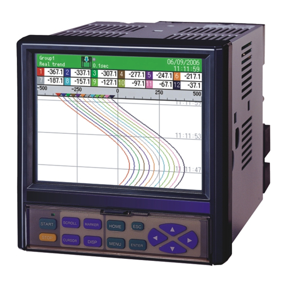
Graphic Recorder
KR2000
General
Instruction Manual
Thank you for purchasing the KR2000 series graphic recorder.
Before using your new recorder, please be sure to read this instruction manual that will advise you on
how to use the instrument correctly and safely and how to prevent problems.
Advertisement
Table of Contents

Related Manuals for Chino KR2000


Summary of Contents for Chino KR2000
- Page 1 General Instruction Manual Thank you for purchasing the KR2000 series graphic recorder. Before using your new recorder, please be sure to read this instruction manual that will advise you on how to use the instrument correctly and safely and how to prevent problems.
-
Page 2: Table Of Contents
CONTENTS Preface HOME settings 1 44 12.1 Setting with HOME settings 44 1 For safe use 2 12.2 Confirming the specifications with 46 HOME settings screen 2 Main features and functions 4 MENU settings 47 3 Before use 5 13.1 Setting MENU setting screen 47... -
Page 3: Preface
PREFACE Thank you for purchasing the KR2000 series graphic recorder. Before using your new recorder, please be sure to read this instruction manual that will advise you on how to use the instrument correctly and safely and how to prevent problems. -
Page 4: 1 For Safe Use
For safe use 1 This section ”FOR SAFE USE” has been compiled to promote the correct use of the instrument in order to prevent human injury or damage to property before they occur. Please read the following information carefully and be sure to observe the warnings and cautions in it. 1. - Page 5 6. Turn off the power supply if an abnormal symptom occurs Turn off the power supply immediately and contact your local CHINO’s sales agent if any abnormal odor, noise or any smoke occurs, or if this recorder becomes high temperature that is too hot to be touched.
-
Page 6: 2 Main Features And Functions
Main features and functions 2 Besides measuring temperature and various industrial quantities of multi channels and displaying real time trends, bar graphs, numeric value, etc. in various formats on 5.6 inch TFT color LCD, this recorder can store data into the internal memory or a memory card (a CF card) and replay them if required. Stored data can be used using commercial software like EXCEL, etc. -
Page 7: 3 Before Use
Before use 3 Check the following items before using the recorder. If something is wrong, contact your local CHINO's sales agent. 3.1 Exterior check Check that the instrument is not broken on the outer side. 3.2 Model check The model number and serial number of the KR 2000 series graphic recorder can be confirmed by the label on the upper side of the case. -
Page 8: Checking Attachments
3.3 Checking attachments Package contains the following attachments. Please confirm. Parts name Quantity Remarks INE-365□ (For KR 2000 series graphic recorder) CD-ROM INE-802□ (Communications interfaces) ①Instruction manual (1 copy) INE-366□ (Mounting/connections edition) A4 19 pages RZMC-01-□ (CF card) ②Mounting For panel mounting bracket For M3.5, input terminal and alarm (digital input) terminal (Spares for ③Terminal... -
Page 9: 4 Installation
Installation 4 4.1 Mounting location In order to avoid unfavorable effects on measurement accuracy and recording operation, mount the KR 2000 series graphic recorder at the following locations. 1) Industrial environment Select a place away from a source generating electric field and/or magnetic field and where mechanical vibrations/shock is not existed. -
Page 10: Method Of Mounting The Panel
Warning ■ Mount on the panel and use (1) The KR2000 series graphic recorder has been designed to be mounted on an indoor instrumentation panel. (2) Use a panel made of a steel plate of 2mm to 6mm in thickness or a panel equivalent in strength. -
Page 11: 5 Connections
Connections 5 5.1 Terminal board arrangement The following diagram shows the terminal board arrangement in which option (alarm relay output [12 points ‘a’ contact], communication interface) are mounted. Connecter for Ethernet is a standard mounting. Communications terminal (M4) (for options) Power/protective conductor terminal (M4) For the connection of communication terminal, refer to the separate “Communication interface... - Page 12 Following figure is terminal board diagram for option (digital input [8 points] + alarm MOS relay output [8 points]) in KR2000, equipped with communication interface. Connecter for Ethernet is a standard mounting. Power/protective conductor terminal (M4) Communications terminal (M4) (options)
-
Page 13: Precautions While Connections
5.2 Precautions while connections Observe the following cautions during connections for securing safety and reliability. 1) Power supply 4) Keep all connection cables away from Use a single-phase power supply having a stable voltage without any waveform distortion for the noises purpose of preventing wrong operations. -
Page 14: Connection Of Power And Protective
5.3 Connection of power and protective conductor terminals 1) Power and protective conductor terminals Protective Power conductor terminal 100-240V AC 50/60Hz 50VA MAX Power supply (voltage, frequency, power consumption) Warning ■Turn off the power supply Be sure to turn off the power supply before connecting the cable to the power supply and protective conductor terminals to prevent an electric shock. -
Page 15: Connection Of Measuring Input Terminal
5.4 Connection of measuring input terminals 1) Measuring input terminals 3) Connection of thermocouple (TC) inputs Be sure to use thermocouple wires (or extension Be sure to turn off the power supply to prevent an electric shock. wires) to the input terminals of this recorder. If a For the connections to the input terminals, use copper wire... -
Page 16: Connection Of Alarm Output Terminals
5.5 Connection of alarm output terminals (option) This is for the recorder with alarm output terminals (option). 1) Alarm output terminal The terminal arrangement depends upon the type of alarm output. Alarm relay output (1a) N.O terminal (M 3.5) Alarm relay output COM terminal (M 3.5) (12 points) - Page 17 (2) Use cables with the crimp style terminals with insulation sleeves for the alarm output terminals. Example of MOS relay and mechanical relay ‘a’ Example of mechanical relay ‘c’ contact output contact output KR2000 series graphic recorder Buffer relay KR2000 series Buffer relay graphic recorder N.
-
Page 18: Connection Of Digital Input Terminals And
5.6 Connection of digital input terminals and function selection (option) This is for the recorder with alarm output terminals (option) 1) Digital input terminal Notes Features of digital input terminal ● Voltage when the contact is open : Approximately 5 V Upper step ●... -
Page 19: Connection Of Communication I/F Terminal
5.7 Connection of communication I/F terminal (partly option) The KR2000 can be communicated with a master unit via Ethernet and RS232C or RS485, and with a slave unit via RS485. *RS-485/232C terminal and serial communication function are optional. RS485/232C terminal... - Page 20 For details, refer to the instruction manual for your personal computer. (1) Example of 9 pin connector KR2000 series graphic recorder Within 15m (2) Example of 25 pin connector...
- Page 21 Protocol converter Internal (9-pin or 25-pin) (SC8-10) circuit Received data 485+485 232+485 KR2000 series KR2000 series KR2000 series graphic recorder 3 graphic recorder graphic recorder 2 Termination resistor 100Ω 1/4W The above figure shows an example of 9 pin connector.
- Page 22 5) Connection of Low order communication RS-485 Connect SA1, SB1 of KR2000 and SA, SB of low order connected instrument like the following figure. Refer to instruction manual of each instrument for detail method of low order instrument connection. Connection example 1...
-
Page 23: 6 Operation
Default setting values have been set at the factory. For actual operation, be sure to execute the following settings. Start Preparation ① Mount KR2000 series graphic recorder to the panel. ( Installation) ② Complete the connections. ( Connection) 5... -
Page 24: 7 Name Of Each Part
Name of each part 7 7.1 Name of the front panel and its major functions Display 5.6 inch TFT color LCD Operation screen: Refer 9 Key cover raised Key cover USB port File on the CF card can be accessed by connecting to the PC. -
Page 25: Name Of The Keys And Their Functions
7.2 Name of keys and their functions Usage and functions of keys differ depending on the operation screen and the setting screen . Key of each screen and their major functions and methods of using Operation screen Setting screen The recording starts Not used START... -
Page 26: Method Of Inputting The Characters
7.3 Method of inputting the characters This screen is used for setting a tag name, a marker text character string and setting/entering a password. Character display column By taking the focus (blue) to upper case English characters, lower case English characters and Kana, the input character list underneath, changes. - Page 27 MEMO - -...
-
Page 28: 8 Screen Switching Method
Screen switching method 8 When the power is turned on, the operation screen is displayed after performing the initial operation for about 10 seconds. (Default settings at the factory: Real time trend screen). When the power is turned on after Initial operation changing the operation screen, the “operation screen that was selected screen... - Page 29 <HOME settings> The settings are used to execute same settings to all channels easily. The items settable are limited. The settings cannot be used during recording. <MENU settings> The settings are used for normal settings. All items can be set and seen during recording, but there are some items not settable.
-
Page 30: 9 Name And Functions Of Operation Screen
Name and functions of operation screen 9 9.1 Common operations of operation screen (Using method of each key) The recording is started. The data of the groups, of which recording conditions are START established, are stored into the internal memory. The groups, of which recording conditions are not established, become the standby state and their recording starts at the time of establishment of conditions. - Page 31 (Displayed data) Measured data displayed on each screen Measured data Contents (Numeric value) The values are displayed based on the display scale settings of each channel. The values are displayed with the number of digits after decimal point of the maximum and minimum values of the display scale..
-
Page 32: Status Bar
9.2 Status bar The status bar is displayed on the top of the screen and displays the status, etc. of this recorder. Normally the back color is green but, when the schedule (Refer to Para. 13.7) is set, the back color becomes gray for the period other than the scheduled period. -
Page 33: Real Time Trend Screen
9.3 Real time trend screen The trends of measured values can be seen like an analog recorder. The pens are displayed on the scale plates corresponding to the values of “Display position” parameters of each channel. When the same “Display position” is set to multiple channels, the scale plates, trends and pens are displayed in the contents of the display scale of the smallest channel number in the group. -
Page 34: Bar Graph Screen
9.4 Bar graph screen The measured values of the channels are displayed with the bar graphs in real time and can be seen visually. The length of the bars and scale plates is displayed in the contents of the display scale with the smallest channel number in the group. -
Page 35: Historical Trend Screen
9.6 Historical trend screen The recorded data are replayed and displayed as the trend display. When the “Historical trend” is selected in the DISP menu (or when the “SCROLL” key on the real trend screen is pressed), data in the internal memory are displayed. -
Page 36: Dual Trend Screen
9.7 Dual trend screen The real time trends and the historical trends are displayed by dividing the screen up and down, and the current data and the past data can be compared. Also the data display displays the current values and values at the cursor position of the historical trends by dividing the screen up and down. -
Page 37: Internal Memory Screen
9.9 Internal memory screen The list of files recorded in the internal memory is displayed. The start date and time, the end date and time (the latest data time for a file being recorded) and the data count are displayed. The files are displayed in the reverse chronological order (latest on the top). - Page 38 Internal memory This recorder records all recorded data into the internal memory as a file. The data are copied to the CF card at a certain storing interval when the recording to this file is completed <Limitations of internal memory> (File capacity) 1 file is completed with maximum volume (refer to the following list).
-
Page 39: Card File Screen
9.10 Card file screen The list of files stored in the CF card is displayed. The start date and time, the end date and time (the latest data time for a file being recorded) and the data count are displayed. The files are displayed in the reverse chronological order (latest on the top). -
Page 40: Initial Settings
Initial settings When the power supply is turned on under the default settings at the factory or when the settings are initialized, the initial settings screen is displayed. Set the indispensable following parameters on use. You can exit without setting the parameters. In that case, this recorder operates with the default settings at the factory. - Page 41 (2) Setting of the power frequency By moving the cursor to the item of the 50Hz/60Hz with the direction key and pressing the ENTER key, pulldown menu is displayed. Select 50Hz or 60Hz in the pulldown menu and press the ENTER key. Confirm and set the power frequency being used.
- Page 42 (4) Input settings By moving the cursor to the item of the input setting with the direction key and pressing the ENTER key, the following input settings screen is displayed. For detailed settings refer to “13.2 Input operation settings” (5) Display settings By moving the cursor to the item of the display setting with the direction key and pressing the ENTER key, the following display settings screen is displayed.
- Page 43 (6) File settings By moving the cursor to the item of the file setting with the direction key and pressing the ENTER key, the following file settings screen is displayed. For detailed settings refer to “13.5 File settings”. - -...
-
Page 44: Flow Chart Of Home Settings & Menu Settings
Flow chart of HOME settings & MENU settings Settings screen HOME settings screen (HOME key) Operation screen MENU settings screen (MENU key) Input operation settings Display settings Alarm settings File settings Totalizer reset settings Schedule settings Marker text settings Memory operation Network settings System settings -... - Page 45 Input parameter settings Recording interval settings Specification confirmation Instrument specifications display List Detail settings Channel parameters Settings of display Group parameters Settings of group Group parameters 2 Detail settings Common parameters Parameter settings of operation screen LCD settings Detail settings Detail settings ON/OFF settings Detail settings...
-
Page 46: Home Settings
HOME settings 12.1 Setting with HOME settings When the [HOME settings] is used, the inputs and recordings of all channels together can be set for the confirmation of input/recording simply. □Operation screen Press the HOME □Home settings screen Press the HOME key on the operation screen to move to the HOME settings. - Page 47 ■Setting the scale ・Set the scale. (It is decided by range type.) This numeric value decides the position of the decimal point. ■Setting the RJ (Reference junction compensation) Set whether the RJ is internal or external. ■Setting the burn out None The burnout function is not used.
-
Page 48: Confirming The Specifications With Home Settings Screen
12.2 Confirming the specifications with HOME settings screen The information of specifications of this recorder can be confirmed. When you have any question on this recorder, contact your nearest distributor after confirming specifications by this screen. □Operation screen Press the HOME... -
Page 49: Menu Settings
MENU settings 13.1 Setting MENU settings screen □Operation screen For setting parameter, press the MENU key on the operation screen to display the parameter items. By selecting the desired item with the direction key and pressing the ENTER key, the screen is switched to the parameter setting screen of this item. - Page 50 □Display settings screen Selection in the “Display settings” Press the key. ENTER Display settings Refer to “13.3 Display settings”. □Alarm settings screen Selection in the “Alarm settings” Press the key. ENTER Alarm settings Refer to “13.4 Alarm settings ”. □File settings screen Selection in the “File settings”...
- Page 51 □Totalizer reset settings screen Selection in the “ Totalizer reset settings ” Press the key. ENTER Totalizer reset settings Refer to “13.6 Totalizer reset settings”. □Schedule settings screen Selection in the “ Schedule settings ” Press the key. ENTER Schedule settings Refer to “13.7 Schedule settings”.
- Page 52 □Memory operation screen Selection in the “ Memory operation ” Press the key. ENTER Memory operation Refer to “13.9. Memory operation”. □Network settings screen Selection in the “Network settings” Press the key. ENTER Network settings Refer to “13.10. Network settings ”. □System settings screen Selection in the “...
-
Page 53: Input Operation Settings
13.2 Input operation settings 13.2.1 Setting contents ・Proceed from the MENU settings ・Move the focus to the setting item with the direction key. ・By pressing the ENTER key on the item for setting, the screen moves to the input screen. By selecting the “Input operation settings”... - Page 54 ■Setting range type (Analog input) KR2120: CH1-12, KR2160: CH1-6 DC voltage 13.8mV,27.6mV,69mV,200mV,500mV,2V,5V,10V,20V, K,E,J,T,R,S,B,N,W-WRe26,WRe5-WRe26,PR40-20, Thermocouple NiMo-Ni,CR-AuFe,Platinel2,U,L Resistance thermometer Pt100,JPt100,Pt50,Pt-Co (Digital input) *For the optional digital input specified CH37-44 Digital input Pulse input Pulse(+), Pulse(-) ■Setting the range ・Set the range. (It is decided by range type.) ■Setting the scale ・Set the scale.
- Page 55 13.2.2 Setting method of formula 1) Formula types Mathematical calculation Four arithmetic operations Symbol Example Remarks are performed. Addition Subtraction X–Y Multiplication Division Reminder Exponential X, Y indicate the formula or the numeric value. Comparison calculation The comparison Symbol Example Remarks calculation is performed Equal value...
- Page 56 Channel data calculation functions The function calculation is Symbol Example Remarks performed. CH(X) Measured data When an error data X is channel No. Calculation result (OVER,UNDER etc.) is PCH(X) data included in the measured data, it becomes “CAL Data at the previous Previous calculated ER”.
- Page 57 2) Totalizing operation For the totalizer, the ITG function or the ITG24 function is used. Do not use totalizing function more than two times in one formula. The results are not calculated correctly. The totalizing function can be used in calculations other than the totalizer. Example:ITG(1)+ITG(2), ITG24(1)-ITG(1), ITG(1)/100 For the totalizer rest, refer to Para.
- Page 58 5) Dew-point temperature Entering method of the formula DEW (T#H) T: Temperature data channel, H: Relative humidity channel The following formula is used for the dew-point temperature. t: Temperature data h: Relative humidity data D: Dew-point temperature ①K=t + 273.15 ②In case of t≧0...
- Page 59 6) Moving average Entering method of the formula AVE (X#T) AVEH (X#T) X: Data channel number, T: Time series interval (second) Mean value of past T seconds is calculated. Difference between AVE and AVEH are the following. AVEH Sampling cycle 1 second 0.1 seconds Range of T...
- Page 60 10) Wind display Entering method of the formula AZI (A) A: Wind data Display the compass point which is changed from direction. Relation of the displayed direction of wind data is in the following list. If A is fractional value, display closest direction. Example: 1.2 → NNE A...
- Page 61 11) Example of arithmetic expression where calculations are combined ・(CH(1)*3-20)/6 (”Raw data of channel 1” X 3 – 20)÷ 6 ・(CH(1)+CH(2))<300 When the total of raw data of channel 1 and channel 2 is less than 300, it becomes 1. ・ABS(CH(1))>=50 When absolute value of channel 1 is 50 or more, it becomes 1.
-
Page 62: Display Settings
13.3 Display settings 13.3.1 Channel parameter ・Proceed from the MENU settings. ・Move the focus to the setting item using direction key. ・By pressing the ENTER key on the item for setting, the screen moves to the input screen. By selecting the display settings on the setting menu screen and then selecting the channel parameters, the following screen is displayed. - Page 63 ■Setting the display position ・The display position (1, 2, 3, and 4) indicates the position of scale plate. For vertical trend graph 1 2 3 4 For horizontal trend graph ■Copy the parameter using the copy function The above shows the setting for copying Ch 01 from Ch 02 to Ch 05. By selecting the [Go] and pressing the ENTER key, the parameters of Channel 01 are copied from Channel 02 to Channel 05.
- Page 64 13.3.2 Group parameter ・Proceed from the MENU settings. ・Move the focus to the setting item using direction key. ・By pressing the ENTER key on the item for setting, the screen moves to the input screen. By selecting the display settings on the setting menu screen and then selecting the group parameters, the following screen is displayed.
- Page 65 13.3.3 Group parameter 2 ・Proceed from the MENU settings. ・Move the focus to the setting item using direction key. ・By pressing the ENTER key on the item for setting, the screen moves to the input screen. By selecting the display settings on the setting menu screen and then selecting the group parameter 2, the following screen is displayed.
- Page 66 13.3.4 Common parameters ・Proceed from the MENU settings. ・Move the focus to the setting item using direction key. ・By pressing the ENTER key on the item for setting, the screen moves to the input screen. By selecting the display settings on the setting menu screen and then selecting the common parameters, the following screen is displayed.
- Page 67 ■Setting the base position of the bar graph ・Set the base position of the bar graph from 0 to 100 on the bar graph screen. When the base position is 0, the bar is displayed based on leftmost (or bottommost). When the base position is 100, the bar is displayed based on rightmost (or uppermost).
- Page 68 Zone The display range of the measured/calculated data is called zone. Since the data can be displayed by setting the zone for each channel, the data can be easily read by displaying the waveforms in separate zones. Select “ON” in the zone usage. Then, selecting the display settings in the setting menu screen and selecting the channel parameters, the following screen with the zone added is displayed.
- Page 69 13.3.5 LCD settings ・Proceed from the MENU settings. ・Move the focus to the setting item using direction key. ・By pressing the ENTER key on the item for setting, the screen moves to the input screen. By selecting the display settings on the setting menu screen and then selecting the LCD settings, the following screen is displayed.
-
Page 70: Alarm Settings
13.4 Alarm settings ・Proceed from the MENU settings. ・Move the focus to the setting item using direction key. ・By pressing the ENTER key on the item for setting, the screen moves to the input screen. By selecting the alarm settings on the setting menu screen, the following screen is displayed. ■Setting the type ・Set the alarm type. - Page 71 ■Setting the maker ・Set the automatically written maker on the trend for alarm activation. When 0 is set, the maker is not written. Differential alarm Differential alarm (Differential lower limit alarm) (Differential upper limit alarm) Difference of measurement values (Absolute value) Uの...
-
Page 72: File Settings
13.5 File settings ・Proceed from the MENU settings. ・Move the focus to the setting item using direction key. ・By pressing the ENTER key on the item for setting, the screen moves to the input screen. By selecting the file settings on the setting menu screen, the following screen is displayed. ■No. - Page 73 <File setting screen> ■Setting the recording cycle ** Seconds 0.1 sec, 0.2 sec, 0.5 sec, 1 sec, 2 sec, 3 sec, 5 sec, 10 sec, 15 sec, 20 sec, 30 sec Minutes 1 min, 2 min, 3 min, 5 min, 10 min, 15 min, 20 min, 30 min, 60 min * If the recording cycle less than 0.5 seconds is set, recording is done in 3 groups and 12 points for each group.
- Page 74 ■Setting the file size Select the file size (period). When the file reaches specified size, the file is completed, and the data after completed is recorded by another name. Pause of [minute] and [hour] is calculated based on 0:00, pause of 1 week is calculated based on 0:00 of Sunday, and pause of 1 month is calculated based on 0:00 of first day.
- Page 75 ■Setting the file size Select the file size (period). When the file reaches specified size, the file is completed, and the data after completed is recorded by another name. Pause of [minute] and [hour] is calculated based on 0:00, pause of 1 week is calculated based on 0:00 of Sunday, and pause of 1 month is calculated based on 0:00 of first day.
-
Page 76: Totalizer Reset Settings
13.6 Totalizer reset settings The totalizer is executed by the calculation settings of each channel. On this screen, set the procedure for resetting the totalized data to 0. All calculations are reset in this setting except ITG24. ITG24 is reset only in base time and not reset every interval. -
Page 77: Schedule Settings
13.7 Schedule settings ・Proceed from the MENU settings. ・Move the focus to the setting item using direction key. ・By pressing the ENTER key on the item for setting, the screen moves to the input screen. By selecting the schedule settings on the setting menu screen, the following screen is displayed. When the schedule is set on this screen, the recording is executed for its set period only. -
Page 78: Marker Text Settings
13.8 Marker text setting ・Proceed from the MENU settings. ・Move the focus to the setting item using direction key. ・By pressing the ENTER key on the item for setting, the screen moves to the input screen. By selecting the marker text settings on the setting menu screen, the following screen is displayed. Without digital input option With digital input option On this screen, up to 50 marker texts (max. -
Page 79: Memory Operation
On pressing the “ENTER” key after entering the file name, setting contents are written. File is saved with extension “.krs”, in “SETUP” folder in the CF card. Settings file can be read and used in other KR2000 series also. ■Reading the settings from card Settings file is read from CF card and the current settings are overwritten. -
Page 80: Network Settings
Example of usage in small scale network When this recorder is used in a small network without connecting to an interoffice LAN or Internet via a router, set the IP address as follows. Instrument IP address Subnet mask KR2000 A 192.168.254.254 255.255.255.0 KR2000 B 192.168.254.253 255.255.255.0 …... - Page 81 13.10.2 DNS settings The DNS server is for converting the address specified with a name into the IP address. When the addresses of the FTP server, POP3 server, SMTP server, etc. are entered with names, make sure to set the DNS server. ・Proceed from the MENU settings.
- Page 82 13.10.3 Web server settings Set the login user name and password for accessing web server. ・Proceed from the MENU settings. ・Move the focus to the setting item using direction key. ・By pressing the ENTER key on the item for setting, the screen moves to the input screen. By selecting the network settings on the setting menu screen and then selecting the Web server settings, the following screen is displayed.
- Page 83 13.10.4 FTP client settings ・Proceed from the MENU settings. ・Move the focus to the setting item using direction key. ・By pressing the ENTER key on the item for setting, the screen moves to the input screen. By selecting the network settings on the setting menu screen and then selecting the FTP client settings, the following screen is displayed.
- Page 84 13.10.5 FTP server settings ・Proceed from the MENU settings. ・Move the focus to the setting item using direction key. ・By pressing the ENTER key on the item for setting, the screen moves to the input screen. By selecting the network settings on the setting menu screen and then selecting the FTP server settings, the following screen is displayed.
- Page 85 13.10.6 SNTP settings ・Proceed from the MENU settings. ・Move the focus to the setting item using direction key. ・By pressing the ENTER key on the item for setting, the screen moves to the input screen. By selecting the network settings on the setting menu screen and then selecting the SNTP settings, the following screen is displayed.
- Page 86 13.10.7 E-MAIL settings This recorder can send e-mails by the event of alarm or time. Specify 8 forwarding addresses in advance. E-mails are sent to the addresses selected from them when the event (Maximum 8 conditions can be registered) is activated. ・Proceed from the MENU settings.
- Page 87 By selecting the forwarding condition, the following screen is displayed. ■Selecting the condition number ・Up to 8 types of the e-mail forwarding condition can be registered. On this screen, set conditions for the number selected here. ■Selecting forwarding condition ・Set the condition for forwarding the e-mail to the forwarding addresses. Item Contents None...
- Page 88 By selecting the “Fixed interval sending CH”, the following screen is displayed. When the “Fixed interval” is specified for the forwarding condition, the e-mail is forwarded by writing the data of the channels, which are registered on this screen, into the message body. ■Condition number ・Select the e-mail forwarding condition number for the settings.
- Page 89 By selecting the “Account”, the following screen is displayed. ■POP3 address This address is used when the SMTP server requires the POP3 authentication. Enter the address of the POP3 server. Do not enter anything when POP3 authentication is not required. ■SMTP address ・Enter the address of the SMTP server.
-
Page 90: System Settings
13.11 System settings 13.11.1 Clock settings Set the date/clock of internal clock of this recorder. ・Proceed from the MENU settings. ・Move the focus to the setting item using direction key. ・By pressing the ENTER key on the item for setting, the screen moves to the input screen. By selecting the system settings on the setting menu screen and then selecting the clock settings, the following screen is displayed. - Page 91 13.11.2 Key lock ・Proceed from the MENU settings. ・Move the focus to the setting item using direction key. ・By pressing the ENTER key on the item for setting, the screen moves to the input screen. By selecting the system settings on the setting menu screen and then selecting the key lock, the following screen is displayed.
- Page 92 13.11.3 Password settings ・Proceed from the MENU settings. ・Move the focus to the setting item using direction key. ・By pressing the ENTER key on the item for setting, the screen moves to the input screen. By selecting the system settings on the setting menu screen and then selecting the password setting, the following screen is displayed.
- Page 93 13.11.4 High order communications settings ・Proceed from the MENU settings. ・Move the focus to the setting item using direction key. ・By pressing the ENTER key on the item for setting, the screen moves to the input screen. By selecting the system settings on the setting menu screen and then selecting the high order communications settings, the following screen is displayed.
- Page 94 13.11.5 Other settings ・Proceed from the MENU settings. ・Move the focus to the setting item using direction key. ・By pressing the ENTER key on the item for setting, the screen moves to the input screen. By selecting the network settings on the setting menu screen and then selecting the other settings, the following screen is displayed.
- Page 95 Each communication types are following. High + low order (read) Record the data in PLC and input data of the product of our company that is connected low order. High + low order (write) Transfer the input data of KR2000 to PLC. - -...
-
Page 96: Setting/Displaying On Web Screen
Setting/Displaying on WEB screen 14.1 Display and settings of the Web screen By using the web browser, the settings relating to inputs and records of this recorder can be configured and the data can be displayed. 14.1.1 Top page By accessing to the IP address of this recorder via the web browser (The figure shows Internet Explorer.), the following screen is displayed after the password authentication. - Page 97 14.1.2 Recorder display The same contents as this recorder are displayed. The keys arranged at the lower part of the screen can be operated like the keys of this recorder. Because of the image file used, it takes more time for loading than other screens.
- Page 98 14.1.4 Input settings This is for changing the settings of the input parameters of this recorder. By clicking the “Set” button after entering each item, the setting contents are written in this recorder. The settings of 6 channels are displayed on 1 screen and the displaying channel block can be switched by selecting the link from the "Channel number"...
- Page 99 14.1.5 Alarm setting This is for changing the the settings of the alarm parameters of this recorder. By clicking the “Set” button after entering each item, the setting contents are written in this recorder. The settings of 6 channels are displayed on 1 screen and the displaying channel block can be switched by selecting the link from the "Channel number"...
- Page 100 14.1.6 Calculation settings Contents of each setting Setting items Contents Calculate Select whether the calculation is used or not. Formula Set the formula with maximum 48 characters. - -...
- Page 101 14.1.7 Group settings This is for changing the settings of the record-related-parameters of this recorder. When the “Set” button is clicked after entering each item, the setting contents are written in this recorder. The settings of one group are displayed on one screen. The group to be displayed can be switched by selecting from the "Group number"...
- Page 102 14.1.8 Maker text setting This is for changing the settings of the maker text parameters of this recorder. When the “Set” button is clicked after entering each item, the setting contents are written in this recorder. By setting the text at the last column (No.
-
Page 103: Read The Recorded Data Using Usb
Check that the CF card is inserted when KR2000 is in operating condition. Open the front compartment and connect the USB port of the PC on which USB port of KR2000 and OS are being installed, with the compatible USB cable. - Page 104 Take care as the contents of the CF card may get destroyed and the data may get lost, when the power supply of KR2000 is disconnected, when the data file is being accessed. Do not remove the USB cable when the data is being accessed.
-
Page 105: Low Order Communications(Read)
10-13 points: number of connection lower-order communication 5. KE3000 instrument x 2 (seconds) 6. LE5000 More than 13 points: number of connection lower-order 7. KR2000/3000 communication instrument x 3 (seconds) 8. LT230 *3 Except JW 9. LT350/370 *4 Data of following PLC made of Mitsubishi Electric can be read. -
Page 106: Instrument
(Terminal resistance is installed to the instrument which is set one end or both ends of standard communication line, however terminal resistance is not installed depend on the environment.) <<Example>> Low order instrument KR2000 KE3000 KR2000 LT300 MELSEC... - Page 107 Data of LT (each series), JU, and JW is assigned like below for CH data. LT JW JU Voltage level CH01 Measured value (PV) CH01 CH01 Voltage level (average) Current value CH02 Measured value (SV) CH02 CH02 Current value (average) Control output value CH03 CH03 Electric value...
- Page 108 16.2.3 Register to the instrument (PLC) (1) Select “system setting” → “low order communications (read)” on the menu screen of the recorder. * “low order communication (read)” is displayed when the recorder has low order communication (read) option. (2) Select the name of the model from the list of “model”. Then register PLC on each COM1 to COM5. (3) Register administrate address of the recorder on “top address”...
- Page 109 16.2.5 Input setting of low order instrument (1) Move the focus to “input computation programming” of “CH” of the left side, press the ENTER key. Display detail setting screen like below. (2) Move the focus to INPUT button for getting setting contents of relevant CH of low order instrument, and press the ENTER key.
- Page 110 (3) When changing the setting from this recorder for appropriate CH of low order instrument, perform following procedure. (The instrument which is not change the setting is not displayed transfer all points transfer button.) When change the setting only displayed CH, move the focus to transmitting, and press the ENTER key.
-
Page 111: Low Order Communications(Write)
Low order communications (write) (option) 17.1 Outline *When use low order communications, set communication type to [High + low order (write)]. (Refer to 13.11.5) Low order communications (write) has the function that communicate for high order instrument and write measurement and calculation data of this recorder to connected low order instrument. This recorder and low order instruments communicate by serial communication of RS-422A or RS-485 communication standard compliance. -
Page 112: Register To The Instrument
17.2 Register to the instrument (1) Select “system setting” → “low order communications (read)” on the menu screen of the recorder *“low order communication (write)” is displayed when the recorder has low order communication (write) option. (2) Select the name of the model from the list of “model”. Then register PLC on each COM1 to COM5. (3) Resister address which is written from this recorder on “top address”... -
Page 113: Scale Calibration
The check and adjustment of measured values need careful cautions for the adjustment work besides tools such as standard tools and reference conditions. When the check and adjustment of measured values are required, contact your local CHINO’s sales agent. -... -
Page 114: Connections
18.4 Connection Connections depend upon the input types. Connect tools such as standard tools to the measuring input terminals to be adjusted. Caution ■ Turn off the power source before connections Turn off the power source before connections for preventing electric shock. In case of DC voltage input CH2, CH5, CH11 are the channels for adjustment in case of KR21*0. - Page 115 In case of the thermocouple input (KR21*0 and KR21*1 are same connection) CH1, CH6, CH12 are the channels for adjustment. For the adjustment of thermocouples, connect to the CH1, CH6, CH12 independently as shown in the right figure. 端 子 部 の 温 度 を 測 定 す る た め の 素 子 が 3 箇 所 あ り 、 ■CH1,CH6,CH12 are used for adjusting 3 Thermocouple wire*...
-
Page 116: Zero And Span Adjustment
18.5 Zero and span adjustment 18.5.1 Calibration screen ・Execute the range adjustment by inputting the zero and span values of the input range to each input channel for adjustment. ・Move the focus to adjusting range by direction key. ・Press the ENTER key at the range to be adjusted to move to the adjustment mode. By pressing the MENU key on the operation screen and then pressing HOME key more than 5 seconds, the following calibration screen is displayed. - Page 117 (2) Since the window indicating the voltage value for inputting is displayed, input its value to this recorder. (3) Adjust the zero point. (Example) For the adjustment of the ±2V range Input the voltage of 0V with the DC standard voltage generator. (4) After inputting the zero point for about 5 seconds, press the ENTER key.
- Page 118 18.5.3 Adjustment of resistance thermometer input range Connect as shown in “18.4 Connection (2) In case of the resistance thermometer input”. In case of the KR21*0, execute the adjustment by inputting the resistance value for the adjustment range of each channels of CH2, CH5, and CH11. In case of the KR21*1, execute the adjustment by inputting the resistance value for the adjustment range of CH2.
- Page 119 (2) Select “Go” at the range of RJ0℃ on the calibration screen, and press the ENTER key. ■Adjustment screen of KR21*1 ■Adjustment screen of KR21*0 (3) After about 30 seconds passed, press the ENTER key. (4) After adjustment, the screen is returned to the calibration screen for all rages. (5) When the adjustments are completed, press the ESC key to return to the menu screen.
-
Page 120: Recommended Parts Replacement Interval
It is recommended to exchange parts periodically as preventive maintenance for using this recorder under good conditions for a long time Warning For replacing parts, ask the service personnel authorized by CHINO. Otherwise, this instrument may not recover properly and also accident may occur. Contact your local CHINO’s sales agent to perform parts replacement. -
Page 121: Troubleshooting
When problem cannot be solved If problem cannot be solved by performing the troubleshooting, contact your sales agent or CHINO with information of 1. Model, 2. Serial No., 3. Description of problem, 4. Other notes. When the instrument need to repaire, underdatnd the following before having it repaired. -
Page 122: Specifications
Specifications ■General Specifications Terminal screws:Po we r t er m i n al ……M4.0 Protective conductor terminal ……M4.0 Rated power voltage: 100-240 VAC,50/60 Hz I n p u t t er m i n a l s ……M3.5 (Universal power supply) Alarm output terminals ……M3.5 Digital input terminal……M3.5 Power consumption: 50VA MAX... - Page 123 Allowable signal source resistance: ・Trend screens: Thermocouple inputs (burnout disabled), DC voltage One of the Real-time Trend, Historical Trend or Dual inputs (max. ±2 V) ….. Less than1 KΩ Trend displays can be selected. DC voltage inputs (±5 to 50 V) ...Less than 100 Ω...
- Page 124 Measuring Range, Accuracy Rating and Display Resolution Note) For the accuracy under the reference operation condition and for thermocouple inputs (internal RJ), the reference junction compensation accuracy is not included. Reference Accuracy Input Reference Accuracy Display Display Input type Measuring range Measuring range range rating...
-
Page 125: Appendix A. Report Application (Sample)
Appendix A. Report Application (Sample) Note This application is a sample application. Inquiries about usage and malfunction cannot be accepted. Please understand it before using. Reports such as daily/monthly reports can be created by using the report application included in the CD attached. - Page 126 A-4-2 Menu structure The configuration contents are compressed and saved as Export project File 1 file. Import project The saved project file is read. Close The application is quitted. Various settings related to this software are executed. Report setup Setup The report creation or printing enabled/disabled for each Report Management group is specified...
- Page 127 A-4-4 Importing project ① Confirmation dialog box for overwriting the configuration is displayed. Click the “OK”. ② Select the file to be read. ③ Read the file. A-4-5 Report settings The setting tables of the Type, Recorded Data, Output, Start Date/Time and password are displayed. The contents of each tab are described below.
- Page 128 (Stored data) Specify the folder in which the stored data is saved. For setting, use the folder selection screen by clicking “Reference”. Copy the file of this recorder to this directory, or specify the data saving directory of the CF card and insert the CF card when the report is created.
- Page 129 (2) Schedule settings When using the daily report, it is convenient if the “Day” is selected with the KR2000 schedule settings, the required day is checked, and set the start and end time is set to the date change time of the daily report because the file is divided at that point.
- Page 130 A-4-6 Report Management Specify whether each report is created for every group. Each time each column is clicked, it changes from * → (Blank) → P. The “— “ indicates that the template is not created. The report is not created if the template is not created. The report marked with “...
- Page 131 A-4-9 Monthly report creation The monthly reports of the groups marked with “ ” in the monthly report column of the report management is created based on the contents in the monthly report template. 1. Specify the period for creating the monthly report. Select the start month and the end month. 2.
- Page 132 A-4-10 Create batch report 1. Select the stored data file for the report. 2. The batch report is created after reading the stored data. 3. After the batch report is created, it is added to the list in the “Report created”. -...
- Page 133 A-5 Edit Report Template Each report is created on the respective template. On the template, create frame of table, fonts, formula indicating cell contents, fixed characters, printing-related-settings, etc. beforehand. A-5-1 Edit daily report template The contents created on the “daily report” sheet are outputted as the daily report. 1.
- Page 134 A-5-2 Edit monthly report template The contents created on the “monthly report” sheet are outputted as the monthly report. 1. Create frames, fixed characters, etc. for the monthly report. 2. Open the input screen by double-clicking on the cell where the data is pasted. Specify the position of the daily report Use here for inputting the created data to be used.
- Page 135 A-5-3 Edit batch report sheet The contents created on the “batch report” sheet are outputted as the batch report. The stored data file is pasted on the “stored data” sheet. Create the report on the “batch report” sheet based on the data on the “stored data”...
- Page 136 32-8,KUMANO-CHO,ITABASHI-KU,TOKYO 173-8632 Telephone :81-3-3956-2171 Facsimile :81-3-3956-0915 E-mail: inter@chino.co.jp Printed in Japan (...
Need help?
Do you have a question about the KR2000 and is the answer not in the manual?
Questions and answers