HPE FlexFabric 7900 Series Installation Manual
Hide thumbs
Also See for FlexFabric 7900 Series:
- Layer 3 ip routing command reference (414 pages) ,
- Security configuration manual (323 pages) ,
- Security command reference (320 pages)
Table of Contents
Advertisement
Quick Links
Download this manual
See also:
Configuration Manual
Advertisement
Table of Contents

Related Manuals for HPE FlexFabric 7900 Series


Summary of Contents for HPE FlexFabric 7900 Series
-
Page 1: Installation Guide
HPE FlexFabric 7900 Switch Series Installation Guide Part number: 5200-1869a Document version: 6W107-20170424... - Page 2 © Copyright 2017 Hewlett Packard Enterprise Development LP The information contained herein is subject to change without notice. The only warranties for Hewlett Packard Enterprise products and services are set forth in the express warranty statements accompanying such products and services. Nothing herein should be construed as constituting an additional warranty. Hewlett Packard Enterprise shall not be liable for technical or editorial errors or omissions contained herein.
-
Page 3: Table Of Contents
Rack-mounting clearance requirements ····················································································· 9 Rack-mounting procedures at a glance ···················································································· 10 Installing the installation accessories for the HPE 7904 switch or HPE 7904 TAA switch ··················· 11 Installing the installation accessories for the HPE 7910 switch or HPE 7910 TAA switch ··················· 13 Rack-mounting the HPE 7904 switch or HPE 7904 TAA switch ····················································... - Page 4 Other specifications ···················································································································· 63 Cooling system ·························································································································· 63 Cooling system for the HPE 7904 switch and HPE 7904 TAA switch ············································· 63 Cooling system for the HPE 7910 switch and HPE 7910 TAA switch ············································· 64 Appendix B FRUs and compatibility matrixes ······································· 66 LPUs ·······································································································································...
- Page 5 USB port ···························································································································· 75 LEDs ······································································································································· 75 HPE 7904 or HPE 7904 TAA chassis LEDs ·············································································· 75 HPE 7910 or HPE 7910 TAA switching fabric module LEDs ························································ 77 LPU LEDs ·························································································································· 78 Power supply LEDs ············································································································· 79 Index ··························································································· 80...
-
Page 6: Preparing For Installation
For regulatory identification purposes, the switches are assigned regulatory model numbers (RMNs). These regulatory numbers should not be confused with the marketing names HPE 7904, HPE 7904 TAA, HPE 7910, and HPE 7910 TAA or the product codes JG682A, JH122A, JG841A, and JH123A. -
Page 7: Temperature And Humidity
• Identify the hot aisle and cold aisle at the installation site, and make sure ambient air flows into the switch from the cold aisle and exhausts to the hot aisle. • Identify the airflow designs of neighboring devices, and prevent hot air flowing out of the bottom device from entering the top device. -
Page 8: Laser Safety
• Inductance coupling. • Electromagnetic wave radiation. • Common impedance (including the grounding system) coupling. To prevent EMI, use the following guidelines: • If AC power is used, use a single-phase three-wire power receptacle with protection earth (PE) to filter interference from the power grid. •... - Page 9 Product Description Quantity Applicable models code M6 screw and floating nut 5185-8965 8 kits All 7900 switches Grounding cable 5184-6723 All 7900 switches ESD wrist strap 5185-8765 All 7900 switches Grounding screw 5185-9579 All 7900 switches Power supply filler module As required 5185-8676 All 7900 switches...
-
Page 10: Installing The Switch
Installing the switch CAUTION: Keep the tamper-proof seal on a mounting screw on the HPE 7904 switch or HPE 7904 TAA switch chassis cover intact, and if you want to open the chassis, contact Hewlett Packard Enterprise for permission. Otherwise, Hewlett Packard Enterprise shall not be liable for any consequence. - Page 11 The HPE 7904 switch and HPE 7904 TAA switch each come with a pair of mounting brackets and a cable management bracket attached together, as shown in Figure Figure 2 Mounting bracket and cable management bracket kit for the HPE 7904 switch or...
- Page 12 As shown in Figure Figure 6, and Figure 7, the HPE 7910 cable management frame can be in the following length if you attach the mounting rail to different positions on the cable frame: − 90 mm (3.54 in). −...
-
Page 13: Rack Mounting Rail Kit
• HPE 7904 switch and HPE 7904 TAA switch A pair of chassis rails and a pair of slide rails are provided with the HPE 7904 switch or HPE 7904 TAA switch. Figure 8 Rack mounting rail kit for the HPE 7904 switch or HPE 7904 TAA switch... -
Page 14: Rack-Mounting Clearance Requirements
Figure 9 Left bottom-support rail 2 RU 1 RU (Rack Unit) = 44.45 mm (1.75 in) (1) Front mark (2) Guide rail (3) Installation hole Rack-mounting clearance requirements Table 5 Rack-mounting clearance requirements Model Router dimensions Rack requirements • IEC-compliant. •... -
Page 15: Rack-Mounting Procedures At A Glance
(2) Card handle (3) Power supply handle Rack-mounting procedures at a glance You can install the HPE 7904 switch or HPE 7904 TAA switch in a 19-inch rack by using the mounting brackets and rack mounting rail kit as described in Figure... -
Page 16: Installing The Installation Accessories For The Hpe 7904 Switch Or Hpe 7904 Taa Switch
Installing the installation accessories for the HPE 7904 switch or HPE 7904 TAA switch The HPE 7904 switch and HPE 7904 TAA switch each have one front mounting position (near the network ports) and one rear mounting position (near the power supplies). The switch also has one primary grounding point (with a grounding sign) and one auxiliary grounding point. - Page 17 Figure 15 Attaching the mounting brackets and chassis rails to the HPE 7904 switch or HPE 7904 TAA switch Connecting the grounding cable to the HPE 7904 switch or HPE 7904 TAA switch CAUTION: The primary grounding point and auxiliary grounding point are located on the left side panel. If you use one of these grounding points, you must connect the grounding cable to the grounding point before you mount the switch in the rack.
-
Page 18: Installing The Installation Accessories For The Hpe 7910 Switch Or Hpe 7910 Taa Switch
Installing the installation accessories for the HPE 7910 switch or HPE 7910 TAA switch The HPE 7910 switch and HPE 7910 TAA switch each have one front mounting position (near the network ports) and one rear mounting position (near the power supplies). The switch also has one primary grounding point (with a grounding sign) and one auxiliary grounding point. -
Page 19: Rack-Mounting The Hpe 7904 Switch Or Hpe 7904 Taa Switch
To install the mounting brackets and grounding cable on the HPE 7910 switch or HPE 7910 TAA switch: Determine the installation positions for the mounting brackets and the grounding cable. - Page 20 Keep the two slide rails at the same height. Figure 19 Installing the slide rails Mounting the HPE 7904 switch or HPE 7904 TAA switch in the rack This task requires two people. To mount the switch in the rack: Wear an ESD wrist strap and make sure it makes good skin contact and is reliably grounded.
- Page 21 Figure 20 Mounting the HPE 7904 switch or HPE 7904 TAA switch in the rack (1) Figure 21 Mounting the HPE 7904 switch or HPE 7904 TAA switch in the rack (2)
-
Page 22: Rack-Mounting The Hpe 7910 Switch Or Hpe 7910 Taa Switch
Rack-mounting the HPE 7910 switch or HPE 7910 TAA switch The HPE 7910 switch or HPE 7910 TAA switch is heavy with FRUs. Before you install the switch in the rack or remove the switch from the rack, remove the FRUs and filler panels from the switch. - Page 23 Figure 23 Attaching the bottom-support rail to the cage nuts with screws (1) Compress the bottom-support rail, making sure the positioning tabs are inserted into the square holes (2) Install fastening screws TIP: Install a screw in each mounting hole of the bottom-support rail to ensure its weight bearing capacity.
- Page 24 Figure 24 Installed bottom-support rails Mounting the HPE 7910 switch or HPE 7910 TAA switch in the rack This task requires two people. To mount the switch in the rack: Wear an ESD wrist strap and make sure it makes good skin contact and is reliably grounded.
-
Page 25: Grounding The Switch
Figure 25 Mounting the HPE 7910 switch or HPE 7910 TAA switch in the rack Grounding the switch WARNING! Reliably connecting the switch grounding cable is crucial to lightning protection and EMI protection. The power input end of the switch has a noise filter, whose central ground is directly connected to the chassis to form the chassis ground (commonly known as PGND). -
Page 26: Grounding The Switch By Using The Pe Wire Of An Ac Power Cord
Attach the two-hole grounding lug at one end of the grounding cable to a grounding point on the switch chassis (see "Connecting the grounding cable to the HPE 7904 switch or HPE 7904 TAA switch"). Remove the hex nut of a grounding post on the grounding strip. - Page 27 Figure 27 Grounding through the PE wire of the AC power cord NOTE: As a best practice to guarantee the grounding effect, use the grounding cable provided with the switch to connect to the grounding strip in the equipment room.
-
Page 28: Installing Frus
Attaching an ESD wrist strap The HPE 7910 switch and HPE 7910 TAA switch each come with an ESD wrist trap. No ESD wrist strap is provided with the HPE 7904 switch or HPE 7904 TAA switch. You need to prepare an ESD wrist strap for the HPE 7904 switch or HPE 7904 TAA switch yourself. -
Page 29: Installing One Switching Fabric Module
Installing one switching fabric module IMPORTANT: If you install only one switching fabric module for the HPE 7910 switch or HPE 7910 TAA switch, install it in the lower switching fabric module slot. To maintain good ventilation, keep the upper filler panel in position. -
Page 30: Installing Fan Trays
Figure 30 Installing two switching fabric modules Installing fan trays Installing the HPE 7904 fan tray CAUTION: You can power on an HPE 7904 switch or HPE 7904 TAA switch only when the switch has two fan trays of the same model installed. -
Page 31: Installing The Hpe 7910 Fan Tray
The installing and removing procedures are the same for the HPE FlexFabric 7904 back (power side) to front (port side) airflow fan tray (HPE 7904 back to front fan tray) and The HPE FlexFabric 7904 front (port side) to back (power side) airflow fan tray (HPE 7904 front to back fan tray). - Page 32 Use a Phillips screwdriver to fasten the captive screws on the fan tray to secure the fan tray in the slot. See callout 2 in Figure 32 Figure If the screws fail to be fastened, verify the installation of the fan tray. Figure 32 Installing one HPE 7910 fan tray...
-
Page 33: Installing A Power Supply
Figure 33 Installing two HPE 7910 fan trays Installing a power supply The HPE 7904 switch or HPE 7904 TAA switch provides two power supply slots and supports 1+1 power supply redundancy. The HPE 7910 switch or HPE 7910 TAA switch provides four power supply slots and supports N+1 and N+N power supply redundancy. - Page 34 Figure 35 Removing a filler panel Unpack the power supply and verify that the power supply model is as required. Correctly orient the power supply, grasp the handle of the power supply with one hand and support its bottom with the other, and slide the power supply slowly along the guide rails into the slot until it has firm contact with the connectors on the backplane.
-
Page 35: Connecting The Power Cord
Do not touch the surface-mounted components directly with your hands when installing or removing an LPU. The switch comes with filler panels installed in all LPU slots except slot 1. For LPUs available for the HPE FlexFabric 7900 Switch Series, see "Appendix B FRUs and compatibility matrixes."... - Page 36 LPU seats on the backplane. Tighten the captive screws with a Phillips screwdriver to secure the LPU in the slot. Figure 38 Installing an LPU on the HPE 7904 switch or HPE 7904 TAA switch (1) LPU-pushing direction...
-
Page 37: Verifying The Installation
Verifying the installation After you complete the installation, verify that: • There is enough space for heat dissipation around the switch. • The grounding cable is connected reliably. • The power supplies are as required. • The power cords are connected correctly. -
Page 38: Replacing Frus
• When both fan trays fail, replace the fan trays one after another. Make sure the device does not operate for more than 3 minutes when no fan trays are installed. The replacing procedures are the same for the HPE 7904 back to front fan tray and HPE 7904 front to back fan tray. -
Page 39: Replacing The Hpe 7910 Fan Tray
• If both fan trays fail, replace the fan trays one after another. Make sure the device does not operate for more than 2 minutes when no fan trays are installed. The replacing procedures are the same for the HPE 7910 back to front fan tray and HPE 7910 front to back fan tray. -
Page 40: Replacing A Power Supply
Figure 40 Removing a switching fabric module (1) Figure 41 Removing a switching fabric module (2) Replacing a power supply To avoid device damage and bodily injury, follow the procedure in Figure 42 to replace a power supply. Figure 42 Removal procedure Switch off the Remove the Remove the... -
Page 41: Replacing An Lpu
To replace a power supply: Wear an ESD wrist strap and make sure it makes good skin contact and is reliably grounded. Release the cable tie securing the power cord to the handle and remove the power cord from the power supply. Push the latch on the power supply to the handle side with your forefinger and clasp your thumb to the handle on the power supply, and pull the power supply part way out of the slot. - Page 42 Figure 44 Removing an LPU from the HPE 7904 switch or HPE 7904 TAA switch (1) Direction for loosening the captive screws (2) Direction for opening the ejector lever (3) Direction for pulling out the LPU Figure 45 Removing an LPU from the HPE 7910 switch or HPE 7910 TAA switch...
-
Page 43: Accessing The Switch For The First Time
Accessing the switch for the first time Setting up the configuration environment The first time you access the switch you must use a console cable to connect a console terminal, for example, a PC, to the console port on the switch, as shown in Figure Figure 46 Connecting the console port to a terminal Connecting the console cable... -
Page 44: Setting Terminal Parameters
Table 7 Console port signaling and pinout RJ-45 Signal DB-9 Signal To connect a terminal, for example, a PC, to the switch: Plug the DB-9 female connector of the console cable to the serial port of the PC. Connect the RJ-45 connector to the console port of the switch. NOTE: Identify the mark on the console port and make sure you are connecting to the correct port. -
Page 45: Configuring The Switch
For more information about login methods, see HPE FlexFabric 7900 Switch Series Fundamentals Configuration Guide. Configuring the basic access function An HPE 7900 switch without any configuration can perform basic data forwarding immediately after it is plugged into a network. To implement more forwarding features, configure the basic network settings in Table 9 on the switch. -
Page 46: Configuration Example
# Assign port Ten-GigabitEthernet 1/0/1 to VLAN 10. [Sysname-vlan10] port ten-gigabitethernet 1/0/1 [Sysname-vlan10] quit For more information about these features, see HPE FlexFabric 7900 Switch Series Configuration Guides. Verifying the network configuration To verify the software version and network configuration, perform display commands in any view. -
Page 47: Connecting The Switch To The Network
Task Command Display the name, model, and system software version of the display version switch. Display the current configuration of the switch. display current-configuration Display the interface status and configuration. display interface brief Display the IP configuration of Layer 3 interfaces. display ip interface brief display ip routing-table Display brief information about active routes in the routing table. -
Page 48: Testing Connectivity
"Appendix C Ports and LEDs." Testing connectivity After you plug the switch into the network, use the ping or tracert command to test the network connectivity. For more information about these commands, see HPE FlexFabric 7900 Switch Series Command References. -
Page 49: Setting Up An Irf Fabric
Setting up an IRF fabric You can use HPE IRF technology to connect and virtualize HPE 7900 switches into a large virtual switch called an "IRF fabric" for flattened network topology, high availability, scalability, and manageability. For more information about IRF, see HPE FlexFabric 7900 Switch Series IRF Configuration Guide. -
Page 50: Planning Irf Fabric Setup
HPE 7900 IRF fabric. Choose HPE 7900 switch models for your network. An HPE 7900 IRF fabric supports up to two member switches. The member switches must be the same model. Select LPUs that can provide 10-GE/40-GE/100-GE ports. -
Page 51: Planning Irf Topology And Connections
On HPE 7900 switches, only 10-GE/40-GE/100-GE ports can be used for IRF connection. The HPE 7900 switches support multi-card link aggregation for IRF ports. You can bind up to eight physical ports to one IRF port. Installing IRF member switches... -
Page 52: Connecting The Physical Irf Ports
Create a Layer 3 interface, assign it an IP address, and make sure the IRF fabric and the remote network management station can reach each other. Use Telnet or SNMP to access the IRF fabric from the network management station. (See HPE FlexFabric 7900 Switch Series Fundamentals Configuration Guide.) Verify that you can manage all member switches as if they were one node. -
Page 53: Maintenance And Troubleshooting
Use display commands to examine the configuration for configuration errors or examine statistics for exceptions. If any configuration error is found, re-configure the switch or restore the factory-default settings. For more information, see HPE FlexFabric 7900 Switch Series Fundamentals Configuration Guide. -
Page 54: Power Supply Failure
Solution To resolve the problem: Verify that the following settings are configured for the terminal: Baud rate—9600. Data bits—8. Parity—None. Stop bits—1. Flow control—None. Emulation—VT100. If the problem persists, contact Hewlett Packard Enterprise Support. Power supply failure Symptom Power supply input or output LED is red. -
Page 55: Switching Fabric Module Failure
Remove and re-install the fan tray to make sure it is fully seated in the slot. Verify that the empty LPU slots and power supply slots are installed with filler panels. Install filler panels to empty slots to guarantee good ventilation. Replace the fan tray. - Page 56 Solution To troubleshoot the interface: Examine the cable connection of the interface. For information about how to correctly connect the cable to an Ethernet interface, see "Connecting the switch to the network." Verify that the cable is in good condition. Use the cable to connect two interfaces of the same type that operate correctly.
-
Page 57: Document Conventions And Icons
Document conventions and icons Conventions This section describes the conventions used in the documentation. Port numbering in examples The port numbers in this document are for illustration only and might be unavailable on your device. Command conventions Convention Description Boldface Bold text represents commands and keywords that you enter literally as shown. -
Page 58: Network Topology Icons
Network topology icons Convention Description Represents a generic network device, such as a router, switch, or firewall. Represents a routing-capable device, such as a router or Layer 3 switch. Represents a generic switch, such as a Layer 2 or Layer 3 switch, or a router that supports Layer 2 forwarding and other Layer 2 features. -
Page 59: Support And Other Resources
Support and other resources Accessing Hewlett Packard Enterprise Support • For live assistance, go to the Contact Hewlett Packard Enterprise Worldwide website: www.hpe.com/assistance • To access documentation and support services, go to the Hewlett Packard Enterprise Support Center website: www.hpe.com/support/hpesc Information to collect •... -
Page 60: Websites
For more information and device support details, go to the following website: www.hpe.com/info/insightremotesupport/docs Documentation feedback Hewlett Packard Enterprise is committed to providing documentation that meets your needs. To help us improve the documentation, send any errors, suggestions, or comments to Documentation Feedback (docsfeedback@hpe.com). When submitting your feedback, include the document title,... - Page 61 part number, edition, and publication date located on the front cover of the document. For online help content, include the product name, product version, help edition, and publication date located on the legal notices page.
-
Page 62: Appendix A Chassis Views And Technical Specifications
Appendix A Chassis views and technical specifications The HPE FlexFabric 7900 Switch Series includes the HPE 7904, HPE 7904 TAA, HPE 7910, and HPE 7910 TAA models. • The HPE 7904 switch or HPE 7904 TAA switch includes a fixed component main processing unit and FRUs, including LPUs, fan trays, and power supplies. -
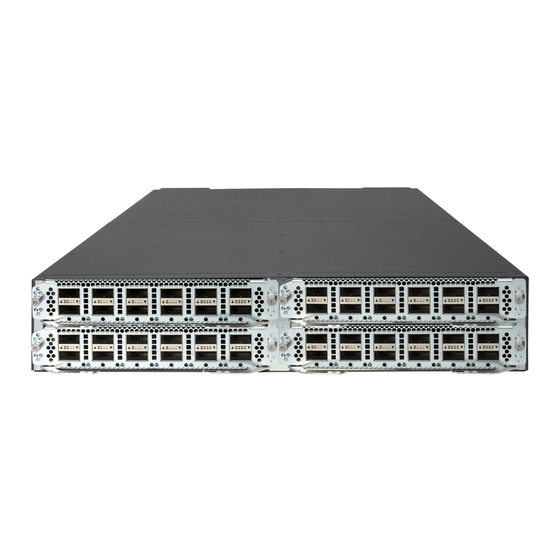
Page 63: Hpe 7910/Hpe 7910 Taa
To ensure good heat dissipation, you must install two fan trays of the same model for the switch. In the figure, the HPE 7904 back to front fan trays are installed in the fan tray slots. HPE 7910/HPE 7910 TAA... -
Page 64: Technical Specifications
You can install one or multiple power supplies for the switch. In the figure, the PSR1800-56A power supplies are installed in the power supply slots. The switch has two fan tray slots. In the figure, the HPE 7910 back to front fan trays are installed in the fan tray slots. -
Page 65: Dimensions
2.5 kg (5.51 lb) LSVM1TGS24FX1 2.3 kg (5.07 lb) LSVM1QGS6C2FX1 2.6 kg (5.73 lb) • HPE FlexFabric 7904 Back (Power side) to Front (Port side) Airflow Fan Tray 0.9 kg (1.98 lb) • HPE FlexFabric 7904 Front (Port side) to Back (Power... -
Page 66: Power Consumptions
100 W LSVM1QGS6C2FX1 121 W 190 W LSV1MPUA1 (main processing unit on the HPE 7904 switch or HPE 7904 334 W 350 W TAA switch) Fan tray power consumption The switch fan trays can automatically adjust the fan speed based on the heat dissipation condition of the switch. -
Page 67: Heat Dissipation
90%. Heat dissipation/hour of the switch is 0.9 × (total power consumption of the cards plus power consumption of the fan tray)/0.9 × 3.4121. For the power consumption of the cards and fan trays of the HPE FlexFabric 7900 Switch Series, see "Power consumptions."... -
Page 68: Other Specifications
Cooling system for the HPE 7904 switch and HPE 7904 TAA switch You must install two fan trays of the same model for the HPE 7904 switch or HPE 7904 TAA switch: • When the HPE 7904 back to front fan trays are used, ambient air flows in through the air vents... -
Page 69: Cooling System For The Hpe 7910 Switch And Hpe 7910 Taa Switch
The HPE 7910 back to front fan trays and HPE 7910 front to back fan trays are available for the HPE 7910 switch and HPE 7910 TAA switch. You can install one or two fan trays for the switch. To install two fan trays, make sure the two fan trays are the same model. - Page 70 • When the HPE 7910 front to back fan trays are used, ambient air flows in through the air vents in the port-side panel, circulates through the chassis and the power supplies, and exhausts through the air vents in the fan tray panels and the power supply panels, as shown in...
-
Page 71: Appendix B Frus And Compatibility Matrixes
Appendix B FRUs and compatibility matrixes LPUs Table 19 describes the LPUs available for the switch. Table 19 LPU specifications Available Produc Connecto Port Port transceiver HPE Description t Code model quantity speed modules and cables • QSFP+ module • QSFP+ DAC HP FlexFabric 7900 •... -
Page 72: Switching Fabric Modules
The LPU models are marked on the LPU panels. For more information about the transceiver modules available for the LPUs, see "Transceiver modules." Switching fabric modules Table 20 Table 21 describe the switching fabric modules available for the HPE 7910 switch and HPE 7910 TAA switch. -
Page 73: Power Supplies
The HPE 7904 switch and HPE 7904 TAA switch support 1+1 power redundancy. The HPE 7910 switch and HPE 7910 TAA switch support N+1 or N+N power redundancy. N can be 1 or 2. The number of power supplies that a switch requires is determined by the power supply mode and... -
Page 74: Fan Trays
Fan trays The HPE 7904 back to front fan tray and HPE 7904 front to back fan tray are available for the HPE 7904 switch and HPE 7904 TAA switch. The HPE 7910 back to front fan tray and HPE 7910 front to back fan tray are available for the HPE 7910 switch and HPE 7910 TAA switch. -
Page 75: Transceiver Modules
Descriptio transmission Code diameter (µm) distance (MHz*km) (nm) 550 m (1804.46 ft) 50/125 HPE X120 500 m (1640.42 ft) 1G SFP LC JD118B 275 m (902.23 ft) Transceiver 62.5/125 220 m (721.78 ft) 9/125 10 km (6.21 miles) HPE X120 550 m (1804.46 ft) - Page 76 Central Modal wavelengt Product Fiber bandwidth Descriptio transmission Code diameter (µm) distance (MHz*km) (nm) Transceiver HPE X120 1G SFP LC JD062A LH40 1550 9/125 40 km (24.86 miles) 1550nm Transceiver HPE X125 1G SFP LC JD063B 1550 9/125 70 km (43.50 miles)
- Page 77 Length HPE X240 10G SFP+ SFP+ 1.2m Direct JD096C 1.2 m (3.94 ft) Attach Copper Cable HPE X240 10G SFP+ SFP+ 3m Direct Attach JD097C 3 m (9.84 ft) Copper Cable HPE X240 10G SFP+ SFP+ 5m Direct Attach JG081C 5 m (16.40 ft)
- Page 78 Table 29 QSFP+ to SFP+ DAC cable specifications Product HPE Description Cable length Remarks code HPE X240 40G QSFP+ to 4x10G SFP+ 1m JG329A 1 m (3.28 ft) Direct Attach Copper Splitter Cable Used for connecting HPE X240 40G QSFP+ to 4x10G SFP+ 3m...
- Page 79 Table 30 CXP transceiver module specifications Central Fiber Modal Produc Connecto Descriptio wavelengt specificatio bandwidth transmissio t code (MHz*km) n distance HPE X150 100G CXP MPO SR 50/125 µm 100 m (328.08 JG881A 850 nm 2000 OM3, MMF 100m Multimode Transceiver...
-
Page 80: Appendix C Ports And Leds
Flash of the switch, for example, to upload or download application and configuration files. LEDs HPE 7904 or HPE 7904 TAA chassis LEDs System status LED The system status LED (SYS) shows the operating status of the switch. - Page 81 Table 33 System status LED description Status Description Steady green The switch is starting. Flashing green The switch is operating correctly. Flashing red The switch is faulty. The switch is powered off. ID LED The ID LED shows the IRF member role of the switch. Table 34 ID LED description Status Description...
-
Page 82: Hpe 7910 Or Hpe 7910 Taa Switching Fabric Module Leds
Status Description LINK No link is present. HPE 7910 or HPE 7910 TAA switching fabric module LEDs Fan status LED The fan status LED (FAN) shows the fan tray operating status. Table 38 Fan status LED description Status Description Green The fan tray is operating correctly. -
Page 83: Lpu Leds
Status Description • The switching fabric module is operating in standby mode. • The switching fabric module is faulty. Management Ethernet port LEDs For description about the management Ethernet port LEDs, see "Management Ethernet port LEDs." LPU LEDs SFP+ port LED Each SFP+ port has a status LED to show the port operating status and activities. -
Page 84: Power Supply Leds
Status Description (One-to-ten A minimum of one link is present on the CXP port. connection) No link is present on the CXP port. Power supply LEDs The PSR1800-56A power supply provides the power input LED (AC OK) and power output LED (DC OK) to show the power input and output status. -
Page 85: Index
Testing connectivity,43 Installing fan trays,25 Transceiver modules,70 Installing IRF member switches,46 Installing switching fabric modules for the HPE 7910 switch or HPE 7910 TAA switch,23 Verifying the installation,32 Installing the switch in a 19-inch rack,5 Verifying the IRF fabric configuration,47...
Need help?
Do you have a question about the FlexFabric 7900 Series and is the answer not in the manual?
Questions and answers