
Related Manuals for HYT TR-800


Summary of Contents for HYT TR-800
- Page 1 5-Tone Model 2009 TR-800 LOGIC & DISP BOARD P/N:410R8001000G0 TR-800 POWER MANAGEMENT P/N:410R800200120 W03441/T04574 8130080000030 04-29-2009...
-
Page 2: Table Of Contents
TR-800 PCB View Top Layer (Logic Board) ...................81 TR-800 PCB View Bottom Layer (Logic Board)..................82 TR-800 PCB View Top Layer (Power Management Board)..............83 TR-800 PCB View Bottom Layer (Power Management Board) ..............84 TR-800 Schematic Diagram (Logic Board).....................85 TR-800 Schematic Diagram (Power Management Board) ..............86... -
Page 3: Revision History
June, 2007 Initial Release 8130080000000 April, 2008 1. ”Programming Guide” is updated; 8130080000010 2. “TR-800 Parts List 1” is updated. April, 2009 The following sections are updated: 8130080000030 1. Programming Guide 2. TR-800 Parts List 1 (Logic Board) 3. MPU and ACC. Connector Pins 4. - Page 4 TR-800 Service Manual Do not expose the repeater to direct sunlight over a long time, nor place it close to heating source. Do not place the repeater in excessively dusty, humid areas or on unstable surfaces. Connect a lightning arrester for the antenna which is installed outdoors. The chassis or the equipment housing must be grounded to minimize any possible shock hazard from lightning strike.
-
Page 5: Repeater Overview
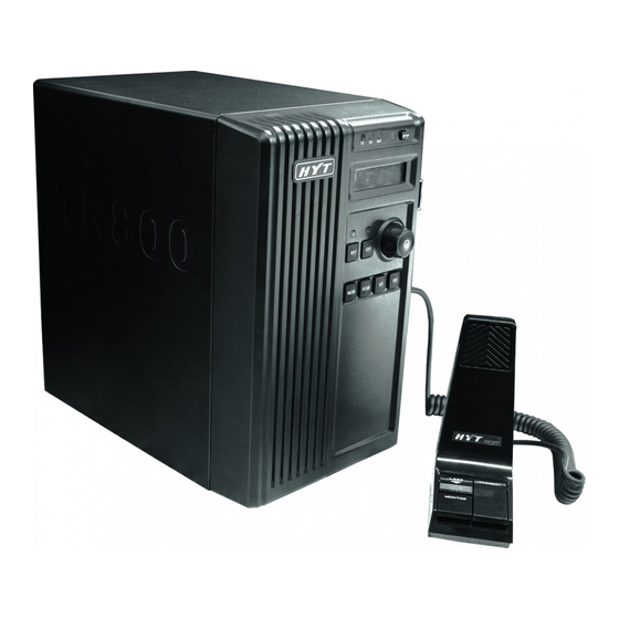
TR-800 Service Manual Repeater Overview 1. Speaker ① 2. LED Indicators LED Indicator ② Green ③ Dark Red ④ Orange ⑤ Blue ⑧ Status LED Indicator Master Slave Green Master Flash red. Slave Flash green. DC power supply works due to AC Dark red mains failure;. - Page 6 The N connector is for connecting with the master radio’s antenna, while the BNC connector is for the slave radio’s antenna. When using a duplexer, choose the correct adaptor on the back of TR-800 according to your antenna connector type. 12. Fan The fan will change its speed automatically as the environment/housing temperature changes.
- Page 7 TR-800 Service Manual 15. Grounding Terminal To avoid lightning strike, ground this terminal via a thick copper wire, or use a lightning arrester if necessary. 16. DC Power Inlet Once the AC mains fails, the equipment will automatically switch to operate with the backup battery if the battery is connected to the port.
-
Page 8: Software Specification
TR-800 Service Manual Software Specification Basic Operation Short press the Power Switch/Volume Control knob to power on the repeater; rotate the Volume Control knob clockwise to adjust the volume to a comfortable level. Press the Up or Dn button to select a desired channel. - Page 9 TR-800 Service Manual CTCSS/CDCSS Set up talkgroups/users with unique CTCSS/CDCSS to prevent unwanted conversations on the same frequency. If CTCSS/CDCSS is set on the current channel, a CTCSS/CDCSS matching will be required on an incoming call. If not set, the radio unmutes to all calls within the communication range on the current channel.
- Page 10 TR-800 Service Manual Mode Description Mode Description Press the SETUP button while the repeater is powered on. The repeater Knockdown Mode enters knockdown mode once the orange LED goes out. Press RPT and OPT buttons when the orange SETUP LED is on. The...
- Page 11 TR-800 Service Manual Note: Before the programming operation, make sure the repeater is in setup mode (the SETUP LED glows orange). LCD Display LCD Icon Description Indicator Description 1. Display channel number. 2. Display channel alias with up to 12 alphanumeric characters (preprogrammed by your dealer).
-
Page 12: Programming Guide
TR-800 Service Manual LED Indicator Description Indicates: Light when the master radio is transmitting. Flash when the master radio is receiving. Flash when the master radio is monitoring channel activities (only for 2-Tone model). Flash when the master radio is being programmed. - Page 13 TR-800 Service Manual Programming Programming Tools The programming software (HR800PE) is used to program the master radio and slave radio. The front panel controller is programmed with the internal DIP switch settings. Uni-directional Repeater Programming the Master Radio 1. Read the master radio and slave radio (The LED flashes red and then green during programming).
- Page 14 TR-800 Service Manual 7. To eliminate squelch tail, click on the drop down menu of “CTCSS Tail Revert Option (Radians)” and select 120° or 180° according to your system requirements. 8. Check the “Ignition Sense” box to enable the Setup/Knockdown function. Click on the drop down menu of “Timed Power Off”...
- Page 15 TR-800 Service Manual Figure 6-3 14. Enter any other special programming requirements in the appropriate window. 15. Close the “Per Personality” window. 16. Double click on “Per Channel - 1” option from the treeview menu of “Per Channel”. 17. Click the “TXRX” tab.
- Page 16 TR-800 Service Manual Figure 6-4 24. Select the “Miscellaneous” tab. 25. Check the “Squelch Tail Eliminator” box to eliminate unwanted noise (squelch tail) during loss of carrier detection. 26. Assign an appropriate personality to a channel in the “Personality List” option. See the screen shown in Figure 6-5.
- Page 17 TR-800 Service Manual Figure 6-5 Figure 6-6...
- Page 18 TR-800 Service Manual Programming the Slave Radio 32. Click on the “+” indicator next to the “Slave” option from the opened HR800PE tree view window. 33. Double click on the “Accessories” option of “Per Radio” from the opened treeview menu of “Slave”.
- Page 19 TR-800 Service Manual arrow in “Horn Alert Logic Signal” and select “1s” if you are using REPEATER STUN FUNCTION. The horn relay contact at the accessory connector of the receiver will close to inform the μP to toggle between the SETUP and KNOCKDOWN status once the receiver successfully decodes a signaling such as 5-Tone sequence.
- Page 20 TR-800 Service Manual Figure 6-9 46. Enter any other special programming requirements in the appropriate window. 47. Close the “Per Personality - n” window. 48. Double click on the “Per Channel - 1” option from the treeview menu of “Per Channel”.
- Page 21 TR-800 Service Manual Figure 6-10 55. Assign an appropriate personality to a channel in the “Personality List” option. Your screen will be shown in Figure 6-11. Figure 6-11...
- Page 22 61. Double click on the “Duplex” option from the opened HR800PE treeview window. 62. Enter a “Radio Power on Message” that will be displayed, such as “TR-800 Rpt”. 63. Click the drop down menu to select a desired “Repeater Hang Time” in steps of 100 millisecond.
- Page 23 TR-800 Service Manual Figure 6-13 65. Check the box beside “Battery Revert Emergency Select” to enable remote emergency alert via the transmitter once the AC mains fails and the back-up battery system will apply. This is an optional function and applies only if you have back-up power system which will engage in case of power outage.
- Page 24 TR-800 Service Manual Figure 6-14 68. Enter any other special programming requirements in the appropriate window. 69. Program the repeater. Basic Uni-directional Repeater – S01 DIP Switch Settings Set the 10 positions of DIP switch S01 according to the following information: The repeater is uni-directional: S01-1 “ON”...
- Page 25 TR-800 Service Manual Bi-directional Repeater Programming the Master Radio 1. Read the master radio and slave radio (The LED flashes red and then green during programming). 2. After the radios are read, click on the “+” indicator next to the “Master” option from the opened HR800PE treeview window.
- Page 26 TR-800 Service Manual 10. Check the “Ignition Sense” box to enable the Setup/Knockdown function. Click on the drop down menu of “Timed Power Off” and select an appropriate time interval. For repeater setup/knockdown, decrease the timer to “0[h]0[m]”. Your screen will be shown in Figure 6-16.
- Page 27 TR-800 Service Manual Figure 6-17 16. Select the “Squelch” tab. 17. Select the “RX Squelch Mode” based upon the squelch type that the repeater will use. Select “CTCSS/CDCSS” if the repeater uses subtone signaling. Your screen will be shown in Figure 6-18.
- Page 28 TR-800 Service Manual 18. Enter any other special programming requirements in the appropriate window. 19. Close the “Per Personality” window. 20. Double click on the “Per Channel - 1” option from the treeview menu of “Per Channel”. 21. Click the “RXTX” tab.
- Page 29 TR-800 Service Manual Figure 6-19 32. Assign an appropriate personality to a channel in the “Personality List” option. Your screen will be shown in Figure 6-20. Figure 6-20...
- Page 30 TR-800 Service Manual 33. Close the “Per Channel - n” window. 34. Double click on the “Per Zone - 1” option from the treeview menu of “Per Zone”. 35. Select the “Zone Channel List” tab. 36. Click the Add or Insert button to add a channel or Del button to delete it. All the channels here should be programmed into the repeater.
- Page 31 TR-800 Service Manual 41. Click the drop down menu of “AUX4” and select “AFO” or “DEO” according to the type of audio to be repeated. “AFO” is filtered and de-emphasized audio limited to 300-3000Hz while “DEO” is flat audio with a response down to 20Hz and suitable for signaling and data repeating.
- Page 32 TR-800 Service Manual Figure 6-23 48. Close the “Miscellaneous” window. 49. Double click on the “Per Personality - 1” option from the treeview menu of “Per Personality”. 50. There is only one personality setting in factory default configuration. Click the “+” button to add personality settings or “...
- Page 33 TR-800 Service Manual Figure 6-24 53. Select the “Squelch” tab. 54. Select the “RX Squelch Mode” based upon the squelch type that the repeater will use. Select “CTCSS/CDCSS” if the repeater uses subtone signaling. Your screen will be shown in Figure 6-25.
- Page 34 TR-800 Service Manual 55. Enter any other special programming requirements in the appropriate window. 56. Close the “Per Personality” window. 57. Double click on “Per Channel - 1” option from the treeview menu of “Per Channel”. 58. Click the “TX/RX” tab.
- Page 35 TR-800 Service Manual Figure 6-26 69. Assign an appropriate personality to a channel in the “Personality List” option. Your screen will be shown in Figure 6-27. Figure 6-27...
- Page 36 75. Double click on the “Duplex” option from the opened HR800PE treeview window. 76. Enter a “Radio Power on Message” that will be displayed, such as “TR-800 Rpt”. 77. Click the drop down menu to select a desired “Repeater Hang Time” in steps of 100 millisecond.
- Page 37 TR-800 Service Manual Figure 6-29 80. Select appropriate alert tone configuration such as tone type, sending times and interval, and specific channel for transmission. 81. Check the “Acc. Channel Select” box to enable remote channel steering function. A maximum of 15 channels are available in binary selection via 4-bit 5-Volt logic input at the rear accessory connector.
- Page 38 TR-800 Service Manual 82. Enter any other special programming requirements in an appropriate window. 83. Program the repeater. Basic Bi-directional Repeater – S01 DIP Switch Settings Set the 10 positions of DIP switch S01 according to the following information: 1. The repeater is bi-directional: S01-1 “ON” and S01-10 “ON”.
-
Page 39: Circuit Description
TR-800 Service Manual Circuit Description Repeater Communication Interface & Display Unit Setup/Knockdown (U0107D, Q0101, Q0103, Q0106, Q0107 and Q0108): The setup/knockdown mode at power-up can be configured via the HR-800 programming software. The electronic switches, Q0106 and Q0108, cause the setup/knockdown action by applying or removing voltage at the ignition control, pin15, of “J0102-Main”. - Page 40 TR-800 Service Manual When the reverse key-up function is enabled, as in the bi-directional repeater configuration, S0101-8 must be on. Q0116 is a DC amplifier (buffer) for the Rx carrier signal from pin6 of “J0102-Main”. An active low state at the input of the NAND gate U0107A, one quarter of a MC14011B, will be conversed to a high state to drive the buffer for the Rx carrier signal.
- Page 41 TR-800 Service Manual Figure Ⅰ Block Diagram...
- Page 42 U0205B-7 to the positive input U0205B-5. The reference voltage at the positive input of U0205B-5 is increased such that the battery voltage must rise above 12Vdc before relay KR01 will reactivate and place the TR-800 back on the battery power. This latching action is used to prevent excessively deep discharging of the battery.
- Page 43 400mA, is used to maintain a “float” charging condition for the battery. After operating the TR-800 station on the battery for a long period, or if the battery reaches the low battery limit of the revert circuit, the battery must be recharged with an external high-current charger.
- Page 44 The radio that performs the transmitting functions in the TR-800 repeater station in general uni-directional application. Slave Radio: The radio that performs the receiving functions in the TR-800 repeater station in general uni-directional application. Bi-directional Repeater: A repeater configuration in which the master and slave radios perform both receiving and transmitting functions.
-
Page 45: Mpu And Acc. Connector Pins
TR-800 Service Manual MPU and ACC. Connector Pins Front Panel of Repeater (MPU Model: uPD780114, Crystal: 9.8304MHz) Pin No. Pin Name Description AVref Connect VDD AVss To GND IC(V To GND (programming pin) adding short-circuit resistor Clock Input Clock output... - Page 46 TR-800 Service Manual KEYBL Keypad backlight control Active: H Rx Tone/I Slave radio signal input Active: L (external pull-up resistor connected) SETUP/I SETUP signal input On: H (rising edge trigger) OPT/I OPT key input Active: L (external pull-up resistor connected)
-
Page 47: Tr-800 Parts List 1 (Logic Board)
TR-800 Service Manual TR-800 Parts List 1 (Logic Board) Part No. Description Ref. No. Print No. 3001060000000 Chip resistor 0603 0Ω J R0158 3001060000000 Chip resistor 0603 0Ω J R0164 3001060000000 Chip resistor 0603 0Ω J R0170 3001060000000 Chip resistor 0603 0Ω J R0176 3001060000000 Chip resistor 0603 0Ω... - Page 48 TR-800 Service Manual Part No. Description Ref. No. Print No. 3001061020010 Chip resistor 0603 1KΩ J R1149 3001061020010 Chip resistor 0603 1KΩ J R1150 3001061020010 Chip resistor 0603 1KΩ J R1151 3001061030010 Chip resistor 0603 10KΩ J R0103 3001061030010 Chip resistor 0603 10KΩ J R0104 3001061030010 Chip resistor 0603 10KΩ...
- Page 49 TR-800 Service Manual Part No. Description Ref. No. Print No. 3001063310010 Chip resistor 0603 330Ω J R0192 3001063320000 Chip resistor 0603 3.3KΩ R1176 3001063330010 Chip resistor 0603 33KΩ J R1170 3001063930010 Chip resistor 0603 39KΩ J R1039 3001063930010 Chip resistor 0603 39KΩ J R1178 3001064710000 Chip resistor 0603 470Ω...
- Page 50 TR-800 Service Manual Part No. Description Ref. No. Print No. 3001064730000 Chip resistor 0603 47KΩ J R1134 3001064730000 Chip resistor 0603 47KΩ J R1161 3001065130010 Chip resistor 0603 51KΩ J R1136 3001065610000 Chip resistor 0603 560Ω J R1167 3001065610000 Chip resistor 0603 560Ω J R1168 3001065620010 Chip resistor 0603 5.6KΩ...
- Page 51 TR-800 Service Manual Part No. Description Ref. No. Print No. 3101071020010 Chip capacitor 0805 1000PF K 50V C0169 3101071020010 Chip capacitor 0805 1000PF K 50V C0170 3101071020010 Chip capacitor 0805 1000PF K 50V C0175 3101071020010 Chip capacitor 0805 1000PF K 50V C0208 3101071030010 Chip capacitor 0805 0.01UF K 25V...
- Page 52 TR-800 Service Manual Part No. Description Ref. No. Print No. 3101074710010 Chip capacitor 0805 470PF K 50V C0197 3101074710010 Chip capacitor 0805 470PF K 50V C0203 3101074710010 Chip capacitor 0805 470PF K 50V C0206 3104074750070 Tantalum capacitor 0805 4.7UF M 10V C0193 3104074750070 Tantalum capacitor 0805 4.7UF M 10V...
- Page 53 TR-800 Service Manual Part No. Description Ref. No. Print No. 3307110100090 LED KPT-1608CGCK CR0107 T4F 3307110100090 LED KPT-1608CGCK CR0108 T3F 3307110100090 LED KPT-1608CGCK CR0111 T4F 3307110100090 LED KPT-1608CGCK CR0112 T2F 3307110100090 LED KPT-1608CGCK CR0113 T2D 3307110100090 LED KPT-1608CGCK CR0114 T3D...
-
Page 54: Tr-800 Parts List 1 (Power Management Board)
4001000000010 Fuse MINISMDC020F-2 5202008100020 Chip socket 52746-0870 8pin J0110 5202011100010 Chip socket B11B-ZR-SM4-TF(LF) 11pin J0106 5202011100010 Chip socket B11B-ZR-SM4-TF(LF) 11pin J0107 TR-800 Parts List 1 (Power Management Board) Ref.No. Print No. Part No. Description Qty. R2103 3001061000000 Chip resistor 0603 10Ω J 1/10W(RoHS) - Page 55 Voltage regulating diode BZX84C27 SOT-23 27V (RoHS) VR0217 71 3302040300010 Voltage regulating diode BZX84C27 SOT-23 27V (RoHS) F0202 72 4011000000010 Recoverable fuse SMD 200F-2 15V 2A (RoHS) 73 410R800200120 TR-800 Power board PCB FR4 1.6T/2L/4P(RoHS) VR0209 74 3302240000030 Voltage regulating diode (RoHS)
- Page 56 TR-800 Service Manual Ref.No. Print No. Part No. Description Qty. VR0218 75 3302240000030 Voltage regulating diode (RoHS) 3003991040010 Surface Temperature Sensor 100KΩ ±1% NTC (RoHS) Rth0201 3099990228000 Color band resistor 0.22Ω J 2W(RoHS) R0269 3103991060020 Electrolytic Capacitor 4*7 10UF ±20% 25V(RoHS) C0230 3103991070090 Electrolytic Capacitor 6*12 100UF ±20% 25V(RoHS)
-
Page 57: Adjustment Description
1set Ammeter 1set Digital Voltmeter 1set Test Jumper Cables (mating with test ports of TR-800 and the communication test set) Communication System Analyzer (CSA such as HP8921 series) 1set Adjustment Radio Configuration Use HR-800PE to program TR-800. Table and table illustrate the factory default settings in a Ⅰ... - Page 58 Base Station Mode Make sure TR-800 is in setup mode and deactivate RPT & OPT functions. TR-800 operates in base station mode with master radio to transmit and slave radio to receive (similar to a duplex mobile radio). Correctly cable the test ports to the communication system analyzer before adjustment.
- Page 59 Uni-directional Repeater Mode (Forward) Make sureTR-800 is in setup mode and activate RPT function. TR-800 operates in uni-directional repeater mode with the slave radio keying the master radio to repeat transmission (forward direction). Correctly cable the test ports to the communication system analyzer before adjustment.
- Page 60 TR-800 Service Manual ≤5% performing wideband specs adjustment Tx S/N: ≥44dB (25kHz) and so does narrowband channel. DO NOT ≥40dB (12.5kHz) perform wideband tuning by entering Max. Power output (without duplexer): tuning mode from a narrowband (12.5kHz) 45±2W(UHF) channel and vice versa.
- Page 61 Uni-directional Repeater Mode (reverse) Make sure TR-800 is in setup mode and activate OPT function. TR-800 operates in uni-directional repeater mode with the master radio keying the slave radio to repeat transmission (backward direction). Correctly cable the test ports to communication system analyzer before adjustment.
- Page 62 TR-800 Service Manual Duplex sensitivity: Adjust the signal output amplitude of CSA to -117(+1/-3dBm) -47dBm; adjust repeater audio deviation to CTCSS sensitivity: 60% System Dev. via the programming -117(+1/-3dBm) Channels with & software; check the modulation distortion and CDCSS sensitivity: without tones.
- Page 63 TR-800 Service Manual Circuit Detect and Temperature-control Test Connect CN0201 (to Power Supply) and CN0204 (to Ext. Battery) with DC power output 13.8V respectively. Measure Adjustment Procedure Condition Specification/Remark Testing Adjusting Instrument Method Point Point When the voltage of CN0201 is gradually increased to 16.4V, the...
- Page 64 TR-800 Service Manual CN0201; gradually increase the voltage of CN0204 to 12V, and the KR01 is activated to toggle to DC power supply with CR0219 illuminating. Heat the Rth0201 with soldering iron or Thermal Soldering iron or hot air Digital hot air gun;...
-
Page 65: Duplexer Instructions
The following procedure assumes that the duplexer is applied and the radios should be connected to the proper ports of the duplexer with the RF coaxial cables provided in the TR-800 kit. The duplexer should not be mounted on the bracket and the tuning screws of the duplexer (on the other side of the cavities, opposite to the RF connectors) should be accessible. - Page 66 TR-800 Service Manual Connect a communications test set, such as HP8921 series, or an RF signal generator to the antenna connector of the duplexer. The test set should be operating in “Generate” mode. To facilitate “hearing” during the tuning procedures, modulate the RF source with a 1kHz tone at 60% system deviation.
-
Page 67: Battery Revert
Battery Revert Overview The battery revert is an integral part of the power management system in the TR-800 repeater cabinet. This accessory allows you to cable your unit to a back-up battery which will engage in case of a power outage. - Page 68 TR-800 Service Manual Battery Type The back-up battery “bank” for the repeater consists of one or more rechargeable batteries. The most readily available batteries are the maintenance free solid gel electrolyte lead-acid and nickel-cadmium (NiCd). Whichever type you choose, the battery must be designed for a service of operation that is typically sporadic and short term and may experience deep discharging before recharging.
- Page 69 TR-800 Service Manual Let the battery operating “capacity” be represented by C . This is based on the current drains during transmitting and receiving, the percentage of times of each and the total time required for battery operation. C may be represented by the following equation: ⎡...
- Page 70 TR-800 Service Manual For our example, let’s consider the 55 A-h operating capacity, over 5 hours of operating with battery, and rated battery discharge times of 5 hours, 10 hours, and 20 hours. 5 hours ⎡ ⎤ ⎛ ⎞ ≈...
-
Page 71: Troubleshooting
TR-800 Service Manual Troubleshooting Table I Troubleshooting for Repeaters (General) Symptom Probable Cause(s) Possible Solution(s) 1a. The power supply is not turned 1a. Turn on the power supply and plug ON or the AC power cord is not the power cord into the AC mains plugged into the AC mains outlet. - Page 72 TR-800 Service Manual 4a.Leaky coaxial cable(s). 4a.Check the coaxial cable(s) and 4. Loss of receiver replace it/them if necessary. sensitivity when the 4b.Loose antenna connector(s). master radio is 4b.Check the antenna connector(s) and 4c.Damaged antenna connector(s). keyed (The repeater replace it/them if necessary.
- Page 73 TR-800 Service Manual 2a. The repeater function is not 2a. Enable the repeater function via enabled (if applicable). RPT/OPT. 2b. The repeater is not in setup 2b. Set the repeater to the setup mode mode (if applicable). through the SETUP contact switch on the front panel.
-
Page 74: Disassembly And Assembly For Repair
TR-800 Service Manual 4a. Tighten the RF cable connectors to the radios, duplexer and antenna. 4b. Replace the faulty component. 4a. Loose RF cable connector(s). 4c. Check: 4b. Damaged antenna or feed line. 4. Low/unstable/no * Tuning of the duplexer... - Page 75 TR-800 Service Manual 3. Attach the front panel with reverse steps. Figure 2 Removing and Attaching the Control Panel 1. Remove the Volume Control knob ①. See Figure 3. 2. Remove the nut using a special spanner . See Figure 3.
- Page 76 TR-800 Service Manual Removing and Attaching the Rear Panel 1. Pull out the ATO fuse ①. See Figure 5. 2. Press the spring latch ② at the two sides of the DC socket and push the DC socket toward the housing to separate the socket from the rear panel ③.
- Page 77 TR-800 Service Manual 5. tach both radios with reverse steps. Figure 6 Figure 7 Removing and Attaching the Switching Power and Power Board 1. Remove the four screws (M3.0X6.0) that secure the switching power using a screwdriver, to remove the switching power ①. See Figure 8.
-
Page 78: Exploded View
TR-800 Service Manual Exploded View 13 14 11 12... -
Page 79: Parts List 2
TR-800 Service Manual Parts List 2 Material No. Description Qty. 7207002200200 Nut M7.0*2.2mm 00(RoHS) 7203002400000 Nut M3.0*2.4mm 00(RoHS) 7103008001040 Machine screw M3.0*8.0mm 04(RoHS) 7102007020010 Self-tapping screw ST1.9*7.0mm 01(RoHS) 7103008020000 Self-tapping screw ST3.0*8.0mm 00(RoHS) 7103006002000 Machine screw M3.0*6.0mm 00(RoHS) 7103008001020 Machine screw M3.0*8.0mm 02(RoHS) 7104006001000 Machine screw M4.0*6.0mm 00(RoHS) - Page 80 TR-800 Service Manual 4220300000200 RF cable (RoHS) 6201171100010 Duplexer bracket 01(RoHS) 4200400000200 Power cord L400MM (RoHS) 4200250000200 Power cord L250MM (RoHS) 6201170001000 Mobile radio bracket 00(RoHS) 1201800U10030 Radio unit 25W (400-470MHz) (RoHS) 4408100002000 RF adaptor (RoHS) 4408100003000 RF adaptor (RoHS)
-
Page 81: Packing
TR-800 Service Manual Packing... -
Page 82: Tr-800 Wiring Diagram
TR-800 Service Manual TR-800 Wiring Diagram... - Page 83 TR-800 PCB View (Logic Board) Top Layer...
- Page 84 TR-800 PCB View (Logic Board) Bottom Layer...
- Page 85 TR-800 PCB View (Power Management Board) Top Layer...
- Page 86 TR-800 PCB View (Power Management Board) Bottom Layer...
-
Page 87: Tr-800 Schematic Diagram (Logic Board)
TR-800 Schematic Diagram (Logic Board) +9VD +5VA TR-800 REPEATER INTERFACE COMMUNICATION & DISPLAY UNIT U0108 +9VD U0109 +5VD +5VD R0146 L0105 7805 7809 601S R0127 Vout Vout +13V8 1.5K U0101 +2V5 TP0101 R0107 R0126 R0101 Q0106 CR0104 R0147 DE-BOUNCE C0128... -
Page 88: Tr-800 Schematic Diagram (Power Management Board)
TR-800 Schematic Diagram (Power Management Board) CR0223 Battery float charging 1N4004 BATTERY FLOAT CHARGER 7.5V DC Bias Q0223 FMT18 CR0212 CR0213 R0268 470 AC-DC 13.8Vdc R0269 0.22/2W F0202-2A VR0209 C0225 C0227 C0228 VR0217 CN0201 7.5V 470p 100uF VR0208 470p To Power Supply... -
Page 89: Specifications
TR-800 Service Manual Specifications General VHF: 136MHz-174MHz; UHF: 350MHz-400MHz; 400MHz-470MHz; Frequency Range 450MHz-512MHz; Channel Capacity 25KHz/12.5KHz Channel Spacing Operating Voltage 13.6V DC±15%/88-264V AC 50/60Hz Duty Cycle 100% Continuous (5/10/25W)/50% Intermittent (45/50W) Standby <1.8A Current Drain <2.5A Receive <13A Transmit Operating Temperature -30 ~+60 ℃... - Page 90 TR-800 Service Manual HYT endeavors to achieve the accuracy and completeness of this manual, but no warranty of accuracy or reliability is given. All the specifications and design are subject to change without prior notice due to continuous technology development. Changes which may occur after publication are highlighted by Revision History contained in Service Manual.
Need help?
Do you have a question about the TR-800 and is the answer not in the manual?
Questions and answers