Table of Contents
Advertisement
Advertisement
Table of Contents

Subscribe to Our Youtube Channel
Summary of Contents for E.F. Johnson Company ATLAS 4500
- Page 1 ATLAS ® 4500 Multimode Station Technical Manual May 2017...
- Page 2 EFJohnson Technologies. All other company and/or product names used in this manual are trademarks and/or registered trademarks of their respective manufacturers. Information in this manual is subject to change without notice. ATLAS 4500 Multimode Station Technical Manual May 2017...
-
Page 3: Table Of Contents
ATLAS 4500 Multimode Station Technical Manual May 2017 Section 1 - Introduction Using This Manual ............. . 1-1 Audience . - Page 4 Reference Clock ............A-8 ATLAS 4500 Multimode Station Technical Manual...
- Page 5 Switch Mode DC-to-DC Convertors........A-17 ATLAS 4500 Multimode Station Technical Manual...
- Page 6 Table of Contents (continued) ATLAS 4500 Multimode Station Technical Manual May 2017...
- Page 7 ATLAS 4500 Introductory View ........
-
Page 8: Figure Page
List of Figures (continued) Figure Page ATLAS 4500 Multimode Station Technical Manual May 2017... - Page 9 ATLAS 4500 Antennas / Antennes ........
-
Page 10: Table Page
List of Tables (continued) Table Page viii ATLAS 4500 Multimode Station Technical Manual May 2017... -
Page 11: Section 1 - Introduction
ATLAS 4500. 1.1.2 Manual Organization This product manual will help you configure and use the ATLAS 4500. This manual is organized into sections to assist you in locating information quickly and efficiently. It contains the following sections: •... -
Page 12: Safety Information
• On the label of the container in which it was supplied. • On the material Safety Data Sheet. • In any local Safety Orders and Regulations. ATLAS 4500 Multimode Station Technical Manual May 2017... -
Page 13: Warnings And Cautions
FCC RF Warning Statement This repeater emits radio frequency (RF) energy when transmitting. Make sure to observe all RF CAUTION energy exposure standards when installing, testing, repairing, and operating this radio equipment. ATLAS 4500 Multimode Station Technical Manual May 2017... -
Page 14: Fcc Part 15.19 Warning Statement
• Reorient or relocate the receiving antenna. • Increase the separation between the equipment and receiver. ATLAS 4500 Multimode Station Technical Manual May 2017... -
Page 15: Atlas 4500 Antennas
• Do not operate the transmitter of a stationary radio (base station or marine radio) when a person is within 17.7 feet (5.4 meters) of the antenna. • The ATLAS 4500 has been approved to operate with the antenna types listed in Table 1.1 with the maximum permissible gain and required antenna impedance for each antenna type indicated. -
Page 16: Ic Rss-Gen, Sec 8.4 Warning Statement
L'exploitation est autorisée aux deux conditions suivantes: • L'appareil ne doit pas produire de brouillage. • L'utilisateur de l'appareil doit accepter tout brouillage radioélectrique subi, même si le brouillage est susceptible d'en compromettre le fonctionnement. ATLAS 4500 Multimode Station Technical Manual May 2017... -
Page 17: Ic Rss-Gen, Sec 8.3 Warning Statement
IC RSS-GEN, Sec 8.3 Warning Statement English The ATLAS 4500 has been approved by Industry Canada to operate with the antenna types listed in Table 1.2 with the maximum permissible gain and required antenna impedance for each antenna type indicated. Antenna types not included in this list, having a gain greater than the maximum gain indicated for that type, are strictly prohibited for use with this device. - Page 18 Ne pas laisser les enfants utiliser l'émetteur équipé du matériel de répéteur. La liste d’avertissement précédente ne vise pas à inclure tous les dangers qui peuvent survenir NOTE lorsque vous utilisez ce répéteur. ATLAS 4500 Multimode Station Technical Manual May 2017...
-
Page 19: Section 2 - Product Overview
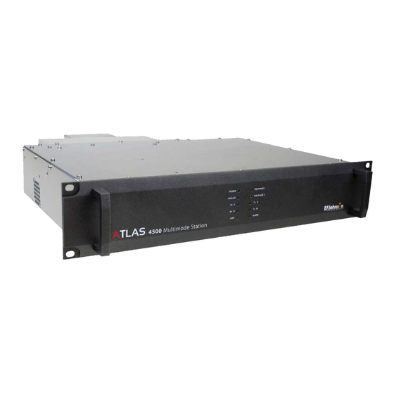
• Specifications 2.1 Functional Description The ATLAS 4500 (Figure 2.1) is a fully software-definable IP-based linear base station that operates in P25 Phase 1 and P25 Phase 2. It has both analog and P25 mixed-mode capabilities. It is available in a range of frequency bands including VHF, UHF, and 700/800 MHz. -
Page 20: Architecture
• Interactive front panel design displays status and diagnostics for rapid troubleshooting. • Flexible software upgrades 2.1.3 Design and Performance • Improved multi-band receiver design provides higher sensitivity along with very high intermodulation immunity for congested prime site locations. ATLAS 4500 Multimode Station Technical Manual May 2017... -
Page 21: Hardware Description
• Front Panel Indicator LEDs • Rear Panel Connectors 2.2.1 Block Diagram The block diagram in Figure 2.2 shows the interconnection and communication paths between ATLAS 4500 internal components. Block Diagram Figure 2.2 ATLAS 4500 Multimode Station Technical Manual May 2017... -
Page 22: Front Panel Indicator Leds
Hardware Description Section 2 - Product Overview 2.2.2 Front Panel Indicator LEDs Figure 2.3 shows the ATLAS 4500 front panel. Table 2.1 contains descriptions of the front panel indicator LEDs. Front Panel Figure 2.3 ANALOG POWER P25 PHASE 1 P25 PHASE 2... -
Page 23: Rear Panel Connectors
Hardware Description Section 2 - Product Overview 2.2.3 Rear Panel Connectors Figure 2.4 shows the ATLAS 4500 rear panel and its connectors. Table 2.2 contains descriptions of the connectors. Rear Panel and Connectors Figure 2.4 Connectors marked by * connect to the ATLAS 4500 logic card... -
Page 24: Software Description
AC power input 2.3 Software Description Administrators use the ATLAS® 6100/6200 Network Management System (NMS) to configure and maintain the ATLAS 4500. Refer to the ATLAS 6100/6200 Network Management System (NMS) Technical Manual. 2.4 Specifications Table 2.3 summarizes ATLAS 4500 general specifications. Table 2.4 summarizes ATLAS 4500 transmitter specifications. -
Page 25: General Specifications
Analog Audio Distortion <2% Frequency Stability ±1 PPM (Internal) [-22°F to +140°F ±0.1 PPM (External Ref: GPS Synchronized) (-30°C to +60°C)] Digital Emission Designator 8K10F1E, 8K10F1D, 8K10F7E Analog Emission Designator 11K0F3E 11K0F3E 16K0F3E, 14K0F3E ATLAS 4500 Multimode Station Technical Manual May 2017... -
Page 26: Receiver Specifications
EFJohnson stations comply with the following standard specifications Standard Specification P25 Digital Operation TIA-102.CAAB-D Digital Phase 2 (TDMA) Operation TIA-102.CCAB-A Analog FM Operation TIA 603-D EMI/EMC NTIA Manual Chapter 5 PSTN Line Isolation FCC Part 68 (USA) ATLAS 4500 Multimode Station Technical Manual May 2017... -
Page 27: Section 3 - Installation And Configuration
• Rack Installation • Connections • Initial Configuration 3.1 Rack Installation EFJohnson performs all rack installation before delivering the ATLAS 4500 to the customer. Refer to Section 6 for information on obtaining technical support and service. 3.2 Connections EFJohnson makes all ATLAS 4500 cable connections for the customer. Refer to Section 6 for information on obtaining technical support and service. - Page 28 Initial Configuration Section 3 - Installation and Configuration Administrators use the ATLAS 6100/6200 Network Management System (NMS) to configure and maintain the ATLAS 4500. Refer to the ATLAS 6100/6200 Network Management System (NMS) Technical Manual. ATLAS 4500 Multimode Station Technical Manual...
-
Page 29: Section 4 - Alignment
E C T I O N Alignment The ATLAS 4500 does not require alignment. Refer to Section 6 for information on obtaining technical support and service. ATLAS 4500 Multimode Station Technical Manual May 2017... - Page 30 Section 4 - Alignment ATLAS 4500 Multimode Station Technical Manual May 2017...
-
Page 31: Section 5 - Maintenance
E C T I O N Maintenance The ATLAS 4500 contains no parts that the customer may maintain. Refer to Section 6 for information on obtaining technical support and service. 5.1 Software Updates Administrators use the ATLAS 6100/6200 Network Management System (NMS) to perform software updates for the ATLAS 4500. - Page 32 Software Updates Section 5 - Maintenance ATLAS 4500 Multimode Station Technical Manual May 2017...
-
Page 33: Section 6 - Technical Support And Service
Regular customer service hours are 8:00 am–5:00 pm U.S. Central Time, Monday–Friday. A technical support subscription service is available or support can be purchased on an as-needed basis. The Customer Service Department can be reached as detailed in Table 6.1. ATLAS 4500 Multimode Station Technical Manual May 2017... -
Page 34: Product Warranty And Repair
This information may also be requested from the Warranty Department by phone (See Table 6.1.). The Warranty Department may be contacted for warranty service reports, claim forms, or any other questions concerning warranties or warranty service. ATLAS 4500 Multimode Station Technical Manual May 2017... -
Page 35: Online Product Registration
(C512, for example) and the model number of the equipment the part is from. You may also send your order by mail or fax. Service Parts Department EFJohnson Technologies 1440 Corporate Drive Irving, TX 75038-2401 Fax: (800) 328-3911 ATLAS 4500 Multimode Station Technical Manual May 2017... -
Page 36: Internet Home Page
Section 6 - Technical Support and Service 6.5 Internet Home Page EFJohnson Technologies has an Internet site that can be accessed for information on the company about such things as products, systems, and regulations. The address is http://www.efjohnson.com/ ATLAS 4500 Multimode Station Technical Manual May 2017... -
Page 37: Appendix A - Vhf Circuit Descriptions
A p p e n d i x VHF Circuit Descriptions Chapter 6 This chapter contains descriptions of the following VHF ATLAS 4500 internal components. For each of the following components, this chapter contains a general description and a schematic description: •... -
Page 38: General Description
IC31 DDS IC. This 345.6 MHz signal is frequency locked to the 10 MHz main reference clock. The 345.6 MHz clock is divided by 8 within IC31 and outputs a 43.2 MHz clock that drives IC32 FPGA. ATLAS 4500 Multimode Station Technical Manual May 2017... -
Page 39: Tx Vco Board
An external 10 MHz clock must have low phase noise/jitter and have a nominal level of 10 dBm NOTE (1.8 Vpp) There is a time delay to re-initialize exciter after changing from internal to external clock or external to internal clock due to synthesizers needing re-programming by the controller. ATLAS 4500 Multimode Station Technical Manual May 2017... -
Page 40: Rf Carrier Generation & Modulation
VCO output (254.64 – 294.64 MHz) from buffer amp IC16 by mixer M1 to provide an output of 119.64 MHz. This passes through a pad then a 150 MHz low pass filter and is amplified by IC15. ATLAS 4500 Multimode Station Technical Manual May 2017... -
Page 41: Exciter Dc Supplies
IC9 is configured as a boost DC-DC converter and provides +25 V DC output for the main PLL. IC3 is a linear regulator regulating the +5.2 V supply down to +5 V DC for linear circuits, A/D, RF amps etc. ATLAS 4500 Multimode Station Technical Manual May 2017... -
Page 42: 135-175 Mhz Receiver Module
Oscillator (VCO) board and an RX board with associated frequency synthesizers, down converter, TCXO, filtering circuits and internal power supply circuits. Receiver input frequency programming is achieved by using serial data connections to an external controller. ATLAS 4500 Multimode Station Technical Manual May 2017... -
Page 43: Schematic Description
PCB. The 8 V supply consists of IC11, TR6 and associated components. The PLL control line varies the VCO frequency (SKT – 1). ATLAS 4500 Multimode Station Technical Manual May 2017... -
Page 44: Reference Clock
The exciter is supplied nominal 13.8 V through SK1-2. This input supply is then distributed to IC1 and IC4. IC1 is configured as a buck DC-DC converter and provides a regulated +5.2 VDC output. ATLAS 4500 Multimode Station Technical Manual May 2017... -
Page 45: 135-175 Mhz Power Amplifier
• Driver module • Main power amp • Cooling system and heat sensor • Coupler for DPD system. • Power detector • Low pass filter • PTT switch • Serial flash memory and regulator ATLAS 4500 Multimode Station Technical Manual May 2017... -
Page 46: Schematic Description
50 Ω feed. The PA operates in a class AB linear mode with plenty of headroom for digital modulation. Extensive decoupling of power supply prevents RF instability. Supply current at CN3 - 2 is < 7 A at 100W. A-10 ATLAS 4500 Multimode Station Technical Manual May 2017... -
Page 47: Power Coupler
TS1 on CN2 – 13, and a serial flash IC11 using I2C bus on CN2- 9, 10. A.4 Controller Board This section contains information on the following Controller Board components: • PA Interface • Exciter Interface A-11 ATLAS 4500 Multimode Station Technical Manual May 2017... -
Page 48: General Description
During power up, the Controller loads the PA calibration data from the Serial flash IC on the I2C bus. This bus is also used for initial PA calibration. A-12 ATLAS 4500 Multimode Station Technical Manual May 2017... -
Page 49: Exciter Interface
The DSP control serial data (RS232) communication is sent to the Controller using a protocol. This controls modulation mode, channel frequency, power etc. The Controller then sends I2C to the Exciter and logic for PTT, sets PA power etc. A-13 ATLAS 4500 Multimode Station Technical Manual May 2017... -
Page 50: Fan Control
1 (C4 FM), P25 phase 2, TX A (time slot A), TX B (time slot B). The CPU A/D inputs monitor voltages for Supply in (48 V), RX VCO 2, RX VCO 1, TX VCO, Forward and Reflected voltages. A-14 ATLAS 4500 Multimode Station Technical Manual May 2017... -
Page 51: Firmware
The TX modulation data is sent synchronously through the I2SCLK, I2SDAT, ISFRM lines to the Exciter through the Controller board. The RX modulation is through 90 MHz IF ports, main and diversity. A-15 ATLAS 4500 Multimode Station Technical Manual May 2017... -
Page 52: Schematic Description
A.6.2.2 Filters The General power supply board has an EMI filter of the AC mains (inside PSU) and filter networks on the 48 V DC O/P for ripple and RFI noise. A-16 ATLAS 4500 Multimode Station Technical Manual May 2017... -
Page 53: Switch Mode Dc-To-Dc Convertors
The 48V supply is DC / DC converted to 5 V by IC2, 13.8 V by IC1 and 24 V by IC3. Each supply capacity is ~ 1.5 A and is fold-back protected. A-17 ATLAS 4500 Multimode Station Technical Manual May 2017... - Page 54 Power Supply Appendix A - VHF Circuit Descriptions A-18 ATLAS 4500 Multimode Station Technical Manual May 2017...
Need help?
Do you have a question about the ATLAS 4500 and is the answer not in the manual?
Questions and answers