Table of Contents
Advertisement
Quick Links
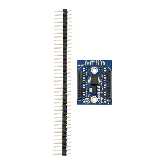
XBee 5V/3.3V Adapter (#32401)
This low cost XBee 5V/3.3V Adapter comes in partially assembled kit form and provides a cost-effective
solution for interfacing your microcontroller to any XBee or XBee Pro module. A voltage regulator and
74LVC244A buffer is included onboard for safe interfacing to a 5 V supply, allowing for easy compatibility
with any Parallax microcontroller.
Features
Onboard 3.3 V regulator and 5 V to 3.3 V logic converters
Four status indicator LEDs for Power, RSSI, Associate and
mode (sleep/ON)
Converts XBee 2 mm pin spacing to 0.100" pin spacing
Provides easy pluggable wire or solder connections
Pin-out compatible with other Parallax XBee Adapter
Boards
Partially assembled kit form for flexible configuration
Compatible with all Parallax microcontrollers
Key Specifications
Power requirements: 3.3–5 VDC
Communication: Serial pass-through to XBee module
Operating temperature: -40 to 158 °F (-40 to 70 °C)
Dimensions (with headers attached): 1.51 x 1.00 x 0.58 in
(38.3 x 25.6 x 14.8 mm*)
Kit Contents
(1) XBee 5V/3.3V PCB (SMD components pre-soldered)
(2) 10-pin 2mm sockets
(1) 40-pin SIP header
Tools Required
Soldering iron (always wear safety glasses when soldering)
Solder (some soldering experience required)
Flux
Diagonal cutters or hobby knife
Copyright © Parallax Inc.
Web Site: www.parallax.com
Forums: forums.parallax.com
Sales: sales@parallax.com
Technical: support@parallax.com
XBee 5V/3.3V Adapter (#32401)
Office: (916) 624-8333
Fax: (916) 624-8003
Sales: (888) 512-1024
Tech Support: (888) 997-8267
v1.2 7/27/2010 Page 1 of 6
Advertisement
Table of Contents

Related Manuals for Parallax 32401


Summary of Contents for Parallax 32401
-
Page 1: Kit Contents
Four status indicator LEDs for Power, RSSI, Associate and mode (sleep/ON) Converts XBee 2 mm pin spacing to 0.100” pin spacing Provides easy pluggable wire or solder connections Pin-out compatible with other Parallax XBee Adapter Boards Partially assembled kit form for flexible configuration Compatible with all Parallax microcontrollers Key Specifications Power requirements: 3.3–5 VDC... -
Page 2: Assembly Instructions
Step 2: Install the 2mm sockets on top of the PCB as shown, and then solder them in place from the bottom side of the board. Copyright © Parallax Inc. XBee 5V/3.3V Adapter (#32401) v1.2 7/27/2010 Page 2 of 6... - Page 3 This step is optional in that you can solder wires directly to the pads if desired. Copyright © Parallax Inc. XBee 5V/3.3V Adapter (#32401) v1.2 7/27/2010 Page 3 of 6...
-
Page 4: Led Status Indicators
XBee Pro modules would be better suited to the XBee SIP Adapter (#32402), or the XBee Adapter Board (#32403) with an external regulator (not included). Module Dimensions Copyright © Parallax Inc. XBee 5V/3.3V Adapter (#32401) v1.2 7/27/2010 Page 4 of 6... -
Page 5: Connection Diagrams
The example code below utilizes a pushbutton connected to Pin 13 on the transmitter board, and an LED connected to Pin 13 the receiver board, while the connection for the XBee 5V/3.3V Adapter remains the same for both boards. Copyright © Parallax Inc. XBee 5V/3.3V Adapter (#32401) v1.2 7/27/2010 Page 5 of 6... - Page 6 P13 while the second program, XBeeRX_PbLed.bs2 receives the state of the pushbutton, displays it on the Debug Terminal, and turns on an LED if the button is pressed. Both programs can be downloaded from the 32401 product page at www.parallax.com. ' {$STAMP BS2} ' {$PBASIC 2.5}...
Need help?
Do you have a question about the 32401 and is the answer not in the manual?
Questions and answers