Table of Contents
Advertisement
Advertisement
Table of Contents

Related Manuals for SainSmart MiniDSO DS211

Summary of Contents for SainSmart MiniDSO DS211
- Page 1 D S 2 1 1 U s e r M a n u a l V1.07...
-
Page 2: Table Of Contents
Contents I. Product Overview II. General Safety Information III. Functions IV. Parameters V. Operational Environment VI. General Inspections VII. Functional Inspections VIII. Battery Charging Instructions IX. Firmware Upgrading X. Getting Familiar with Device XI. Measurement Instructions XII. Certification Marks... -
Page 3: Product Overview
I. Product Overview DS211 is a digital storage oscilloscope based on an ARM Cortex compatible 32-bit platform, equipped with a 320*240 color screen and Micro USD interface which serves as PC connection and charging. Compact size, simple operation, easy to use.It can meet the basic requirements for school experiment, appliance repair and electronic engineering. -
Page 4: Functions
III. Functions 0-200KHz Analog bandwidth 1MSa/s Maximum sampling rate Maximum sample memory depth 1uS/Div~2S/Div Horizontal sensitivity (1-2-5sequence step) 20mV/Div~10V/Div(x1probe) Vertical sensitivity 0.2V/Div~100V/Div(x10probe) >500KΩ Analog input impedance Maximum input voltage 40Vpp(x1probe) Coupling AC/DC Auto,Normal,Single,Scan Synchronous mode Rising/Falling edge trigger Trigger mode Ascend/Descend Edge Tirgger Mode Signal sequence/cycle/duty ratio,... -
Page 5: Parameters
IV. Parameters Weight Display color Battery 500mAH 320×240 Screen Resolution Via micro USB Cable PC Comection Via micro USB Cable Recharging 2.8'' full color TFT LCD Screen Size 106mm×55.5mm×11mm V. Operational Environment Humidity: :40°C~ Operating HighTemperature 50°C,0%~60%RH Conditions 0°C ~ 40°C,10% 90%RH LowTemperature: 40°C ~ HighTemperature:... -
Page 6: General Inspections
VI. General Inspections When you get a new DS211 oscilloscope, you are advised to inspect the product by the following steps. 1. Inspect damages caused by shipping.If the packaging carton or the protection pad is seriously damaged, keep the package until the oscilloscope &... -
Page 7: Firmware Upgrading
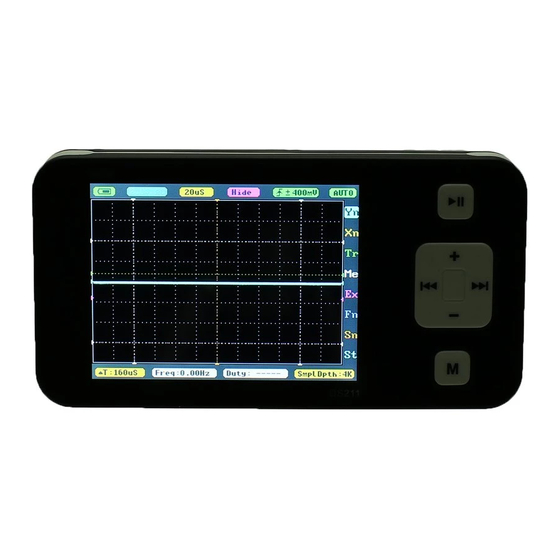
IX. Firmware Upgrading To upgrade the firmware of oscilloscope, please carry out the operationfollow the steps below: 1. Open web browser to visit www.minidso.com, download the newest firmware appropriate toof your oscilloscope to your PC. 2. Press “—” button on DS211 and switch on the Power to enter into DFU firmware upgrading mode. - Page 8 See below for functions of each button: Run/pause button Save parameter Slide Up Slide Down Set parameter(Reduce,Slide Left) Set parameter(Increase,Slide Right) On/Off Sub-menu Save BMP(long press) Auto Fit(double press) 2、Main Screen Introduction A B C Parameters Options Parameters Main Screen Note that each item's color in Parameter Area is the same as that in Measurement Area.
-
Page 9: Measurement Instructions
XI. Measurement Instructions 1、Parameters Introduction Menu Options Functions (Press or operate) Battery supply/USB charging 20mV—10V(1-2-5stepping) Ordinate unit amplitude AC/ DC coupling method 1uS—2S(1-2-5 ) Abscissa unit amplitude stepping Double waveform calculation -Inp/Data/-Data/Inp+D/ (Inp refers to current waveform; D-Inp/Inp-D D/Data refers to waveform saved previously) Trigmode:Rising/ falling edge... - Page 10 2、Options Introduction Parameter Notes Options Y-axis function setting (See P9) X-axis function setting (See P9) Trigger function setting (See P10) Measurement function setting (See P10) Waveform calculation function setting (See P11) Saving and loading function setting (See P12) Waveform output parameter setting (See P13) System function setting (See P13) 3、Specific Parameter Introduction Option Setting Method...
- Page 11 1)Yn Parameter Notes Y Ranges Ordinate unit amplitude Coupling Coupling method ProbeAtt Probe multiple choice X1/X10 Y Offset Wave adjustment Y axis CursorV1 measurement cursor V1 CursorV2 measurement cursor V2 Hide_Vn Show/hide measurement cursor 2)Xn Parameter Notes TimeBase Abscissa unit amplitude ViewPosi Move horizontally to check waveform SmplDpth...
- Page 12 3)Tr Parameter Notes Synchronous mode SyncMode AUTO/NORM/SINGL/SCAN TrigMode trigger mode: Rising/falling edge Automatic adjustment(Icon "F" will appear when Auto Fit open, doublr click Button M to auto fit. Threshol Horizontal Triggering Position Level) Sensitiv Horizontal Triggering accuracy Display/Hide Horizontal Triggering Position Level Hide_Tri 4)Me Parameter Notes Freq...
- Page 13 5)Ex Parameter Notes -Inp/Data/-Data/Inp+D/D-Inp/Inp-D Ext Refn Signal position Ext Posi Ext Hide Show/hide signal calculation Hide the two waveform computation line (purple line): Position the cursor on "EX" option, press "M” to pop-up window, select "Ext Hide" option, and change the parameter value at the blinking cursor to “Hide”...
- Page 14 6)Fn Parameter Notes Save Bmp Save bmp file (waveform figure) into flash disk Save Dat Save dat file into flash disk Save Buf Save buf file (sampling buffer data) into flash disk Save Csv Save csv file (export sampling buffer data) into flash disk Save Svg Save svg file (sampling buffer figure) into flash disk Load Dat...
- Page 15 7)Sn Parameter Notes Out Type Output signal type Out Freq Output signal frequecy Out Duty Output signal duty cycle 8)St Parameter Notes B-Light Adjust backlight brightness(Press to adjust brightness) Auto Cal Calibrate Zero(Press to auto calibrate, save setting per prompt) Restore Data(Press to auto calibration, save setting per prompt) Restore...
-
Page 16: Certification Marks
XII. Certification Marks FCC compliance statement This device is complied with the regulation in the 15th part of FCCregulation. Operation is subject to the following two conditions: (1)This device may not cause harmful interference. (2)This device must accept any interference received, including theinterference that may cause undesired operation.
Need help?
Do you have a question about the MiniDSO DS211 and is the answer not in the manual?
Questions and answers