Table of Contents
Advertisement
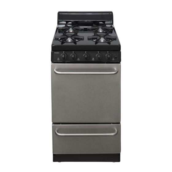
USE AND CARE MANUAL AND INSTALLATION INSTRUCTIONS
GAS RANGE
Use and Care
Installation
(Propane) Gas
NOTE TO CONSUMER:
Please retain this manual for future reference.
NOTE TO INSTALLER:
Please leave this manual and other literature with the
consumer for future use.
Inside front cover
1-2
3
4
5-6
7
8
9
10-12
13
14-15
16
17
18
19
19
20
20
21
21
22-24
25-26
27
27
27
28
29
30-32
Advertisement
Table of Contents

Subscribe to Our Youtube Channel
Related Manuals for Premier SAK600BP

Summary of Contents for Premier SAK600BP
-
Page 1: Table Of Contents
USE AND CARE MANUAL AND INSTALLATION INSTRUCTIONS GAS RANGE Important Safety Instructions Inside front cover General Safety Precautions Use and Care Surface Cooking Griddle (Optional on Some Models) Using your Oven Using your Broiler Operating your Range During an Electrical Power Failure Clock and Timer (Some Models) Care and Cleaning 10-12... -
Page 2: Important Safety Instructions
IMPORTANT SAFETY INSTRUCTIONS To reduce the risk of the appliance tipping, it must be WARNING: If the information in this secured by a properly installed anti-tip device. To check manual is not followed exactly, a fire or if this device is installed properly, remove the broiler explosion may result, causing property drawer to inspect the anti-tip bracket or grasp the top damage, personal injury or death. -
Page 4: General Safety Precautions
GENERAL SAFETY PRECAUTIONS 15. DO NOT HEAT UNOPENED CONTAINERS OR FOOD ON SURFACE BURNERS OR IN THE OVEN. Buildup of pr essur e may cause the container to bur st and r esult in ser ious per sonal har m and/or damage to the range. -
Page 5: Surface Cooking
SURFACE COOKING BURNER LIGHTING SOURCE The burners on your range need an electrical source to ignite the POWER PACK burners. The electricity required to light the burners may come from an electrical outlet or from a battery power pack. Ranges without a power cord have a battery power pack located in the lower right corner of the range. -
Page 7: Using Your Oven
USING YOUR OVEN PILOT To use your oven, push and rotate the oven control counterclockwise to the “PILOT” or “LITE” position. Once in the “PILOT” or “LITE” position, push in on the knob as far as possible and hold for 10 sec. After holding the control knob in for 10 sec. re- lease the oven knob. -
Page 10: Operating Your Range During An Electrical Power Failure
OPERATING YOUR RANGE DURING AN ELECTRICAL POWER FAILURE WARNING: USE EXTREME CAUTION WHEN LIGHTING BURNERS THIS WAY. LIGHTING TOP BURNERS TOP BURNER 1. Hold a lighted match to the desired burner head. 2. Push and turn the control knob to the “LITE” or “START”... -
Page 11: Clock And Timer (Some Models)
CLOCK AND TIMER (Optional on Some Models) ELECTRONIC CLOCK AND TIMER TO SET TIME OF DAY: Depr ess “CLOCK” button (a tone will sound). Depr ess “UP” button to set the time up, or depress “DOWN” button to set the time down. Tapping the “UP” OR “DOWN” button will increase or decrease the time by 1 minute. -
Page 14: Care And Cleaning
CARE AND CLEANING CLEANING BROILER PAN (if equipped): After broiling, remove the broiler pan and tray after allowing them to cool. Wash in warm, soapy water. * BROILER PAN AND TRAY MUST BE IN PLACE FOR ANY COOKING OPERATION. Slide out to remove Push up under center and roll... -
Page 16: Backguard Installation
INSTALLATION INSTRUCTIONS PORCELAIN BACKGUARD INSTALLATION 1. Remove range main top. See Page 11. 2. Position backguard down over flue box and onto the range main sides. 3. Attach backguard to range main sides with (2) (A) bolts and (2) (B) nuts each side. 4. - Page 17 PORCELAIN BACKGUARD MAIN TOP BACKGUARD FASTENERS REQUIRED #10-24 X 3/8” #10-24 Hex Keps Phillips Truss Hd bolt BACKGUARD THERMOPLASTIC END CAP BACKGUARD FASTENERS REQUIRED #8 X 1/2” Phillips #10-24 X 3/8” Countersink Hd Phillips Truss Hd screw bolt MAIN TOP #10-24 X .75”...
-
Page 18: Clearances And Location
INSTALLATION INSTRUCTIONS MAXIMUM AND MINIMUM CLEARANCES The sides of the range can be flush to combustible material below the cooking top. The back of the range can be flush to combustible material. A minimum clearance of 5 inches is required between the range and com- bustible construction extending from the cooking surface to 18 inches above the level of the cooking surface. -
Page 19: Anti-Tip Bracket Installation
INSTALLATION INSTRUCTIONS ANTI-TIP BRACKET INSTALLATION WARNING The anti-tip bracket is installed to prevent the range from tipping forward as the result of excessive down- ward pressure on the open end of the oven door. All A child or adult can tip the range and be killed. Install the anti-tip device to the floor or the wall of the structure. -
Page 20: Connecting The Range To Gas
INSTALLATION INSTRUCTIONS CONNECTING THE RANGE TO GAS The installation of this gas range must conform with the local codes, or in the absence of local codes, with the National Fuel Gas Code, ANSI Z223.1/NFPA 54 “Latest Edition” in the U.S.A. or in Canada, the Natural Gas and Propane Installation Code, CSA B149.1. -
Page 21: Testing For Gas Leaks
INSTALLATION INSTRUCTIONS WARNING: DO NOT USE A FLAME TO CHECK FOR GAS LEAKS TESTING FOR GAS LEAKS Before turning on the gas, be sure that all range valves are in the “OFF” position. Turn on the gas and check each joint or connection with a soap and water solution, including the inlet and outlet sides of the regulator. Never test for leaks with a lighted match or open flame. -
Page 22: Powering Cordless Ranges (Some Models)
INSTALLATION INSTRUCTIONS POWERING CORDLESS RANGES (SOME MODELS) It is not necessary to connect your range to a plug-in outlet in your home. The burner ignition comes from a DC source (battery power pack). INSTALLING THE DC POWER PACK (8) AA Alkaline Batteries Before any of the burners can be lighted, it is necessary to locate the power pack that is located in the range oven section. -
Page 23: To Light Top Pilots (Pilot Ignition Models)
INSTALLATION INSTRUCTIONS TO LIGHT TOP PILOTS (Standing Pilot Canadian Model Ranges Only) 1. Be sure the surface burner control knobs are in the “OFF” position. 2. Remove the grates and tray inserts (if any) and remove the cook top. See Page 11. 3. -
Page 24: Converting Range From Natural Gas To Lp
CONVERTING RANGE FROM NATURAL GAS TO PROPANE GAS IMPORTANT: READ PRIOR TO STARTING THE CONVERSION PROCESS: Because your r ange may be fitted with one of three different types of oven systems, it is necessary to determine which system the range employs in order to be successful making the range conversion. - Page 25 CONVERTING RANGE FROM NATURAL GAS TO PROPANE GAS STEP 3 METHOD A Conver t the Range Oven ther mostat. GAS CONVERSION SCREW The oven thermostat control is at the center front of the range located behind the oven control knob and control panel. Locate the brass propane conversion screw the oven thermo- stat as shown in Fig.
- Page 26 CONVERTING RANGE FROM NATURAL GAS TO PROPANE GAS STEP 4 METHOD A or B Conver t Oven ORIFICE HOOD Burner: The oven burner orifice is located beneath NATURAL GAS the inlet to the oven burner at the lower rear LP GAS portion of the broiler section.
-
Page 27: Converting Range From Propane Gas To Natural Gas
CONVERTING RANGE FROM PROPANE GAS TO NATURAL GAS IMPORTANT: READ PRIOR TO STARTING THE CONVERSION PROCESS: Because your r ange may be fitted with one of three different types of oven systems, it is necessary to determine which system the range em- ploys in order to be successful making the range conversion. -
Page 28: Tural Gas
CONVERTING RANGE FROM PROPANE GAS TO NATURAL GAS STEP 3 METHOD A Conver t the Range Oven ther mostat. GAS CONVERSION SCREW The oven thermostat control is at the center front of the range located behind the oven control knob and control panel. Locate the brass gas conversion screw on the right side of the oven thermostat as shown in Fig. -
Page 29: Check Surface Burner Ignition
INSTALLATION INSTRUCTIONS CHECK SURFACE BURNER IGNITION Simultaneously push in and turn a top burner knob to the LITE or START position. On Electric Spark Ignition Models, you will hear a clicking sound indicating the proper operation of the spark module. Once the air has been purged from the supply lines, the burner will light. -
Page 30: Adjust Air Shutter, If Necessary
INSTALLATION INSTRUCTIONS ADJUST AIR SHUTTERS, IF NECESSARY AIR SHUTTER TOP BURNERS: The air shutter adjustment for each top burner is located at the Open end of the top burner venturi tube and rests on the orifice hood of the top burner valve. Should the air shutter need ad- justing, slide the air shutter to allow more or less air into the burner flame as needed. -
Page 31: Wire Diagrams
WIRING DIAGRAMS SUPPLY CORD 12VDC (8) AA 120V AC 15 AMPS BATTERIES HOT SURFACE IGNITION SYSTEM BATTERY IGNITION SYSTEM SUPPLY CORD 120V AC 15 AMPS SPARK/THERMOCOUPLE IGNITION SYSTEM... -
Page 32: Before You Call For Service
BEFORE YOU CALL FOR SERVICE Before you call for service, review this list. It may save you time and expense. This list includes common oc- currences that are not the result of defective workmanship or materials in this appliances. Find your problem here Possible cause How to fix it SURFACE BURNERS... - Page 33 BEFORE YOU CALL FOR SERVICE Find your problems here Possible cause How to fix it continued: Flame is orange. Dust particles in main line. Allow burner to operate for a few minutes until flame turns blue. Make sure temperature control is set at the desired temperature.
-
Page 34: Before You Call For Service
BEFORE YOU CALL FOR SERVICE Find your problems here Possible cause How to fix it Nuisance sparking while oven is Improperly grounded or reversed Have outlet corrected by a quali- in operation. polarity electrical outlet. fied electrician. Smoke or odor on initial oven This is normal. - Page 35 With this in mind, it is important that you read this booklet. Acquaint yourself with features and follow the use and care suggestions for complete satisfaction. Most parts are available through Peerless Premier Appliance Co. or a reputable Parts and Service Re- tailer.
Need help?
Do you have a question about the SAK600BP and is the answer not in the manual?
Questions and answers