Table of Contents
Advertisement
UNIVERSAL TRANSMITTER UT-94
REF NO: m98A/om/101
Issue NO: 15
User's Manual
UT-94 Universal Transmitter
Masibus Automation and Instrumentation Pvt. Ltd.
B/30, GIDC Electronics Estate,
Sector-25, Gandhinagar-382044, Gujarat, India
Phone : +91-79-23287275/79.
Fax : +91-79-23287281.
Email: support@masibus.com
Web: www.masibus.com
User's Manual
Page 1 of 25
Advertisement
Table of Contents

Related Manuals for Masibus UT-94


Summary of Contents for Masibus UT-94
- Page 1 UNIVERSAL TRANSMITTER UT-94 REF NO: m98A/om/101 Issue NO: 15 User’s Manual UT-94 Universal Transmitter Masibus Automation and Instrumentation Pvt. Ltd. B/30, GIDC Electronics Estate, Sector-25, Gandhinagar-382044, Gujarat, India Phone : +91-79-23287275/79. Fax : +91-79-23287281. Email: support@masibus.com Web: www.masibus.com User’s Manual...
-
Page 2: Table Of Contents
UNIVERSAL TRANSMITTER UT-94 REF NO: m98A/om/101 Issue NO: 15 Contents Introduction........................... 4 Ordering Code ........................4 Installation ..........................5 Environment: ........................5 Mounting: .......................... 5 Installation Dimensions: ....................5 Removal: ........................... 5 Front Panel ........................... 6 Dimensions ........................... 7 Terminal Position Detail: ...................... 8 Menu Function List ....................... -
Page 3: Safety Precautions
UNIVERSAL TRANSMITTER UT-94 REF NO: m98A/om/101 Issue NO: 15 SAFETY PRECAUTIONS To ensure that the device can be operated safely and all functions can be used, please read these instructions carefully. Caution: Never carry out work when the Power is turned on, this is dangerous. -
Page 4: Introduction
UNIVERSAL TRANSMITTER UT-94 REF NO: m98A/om/101 Issue NO: 15 1. Introduction This is a micro-controller based Universal Transmitter which retransmits the Universal Inputs given, into the required Voltage or current. This instrument provides isolation at 4 levels: a) Between input and Power supply b) Between output and Power supply. -
Page 5: Installation
UNIVERSAL TRANSMITTER UT-94 REF NO: m98A/om/101 Issue NO: 15 2. Installation 2.1 Environment: Caution: Do not install the unit where it is subjected to continuous vibration. Do not subject the unit to physical impact. 2.2 Mounting: The unit can be snapped onto all DIN rails according to EN 60715. The device must be mounted horizontally (input terminal blocks facing downwards) 2.3 Installation Dimensions:... -
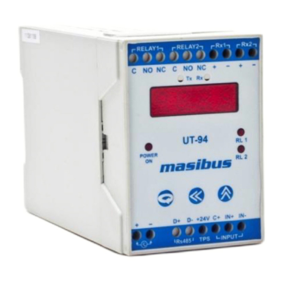
Page 6: Front Panel
UNIVERSAL TRANSMITTER UT-94 REF NO: m98A/om/101 Issue NO: 15 3. Front Panel – This key is used to start menu, scroll through the menu and save values. ENTER / SCROLL Key – This key is used to select the menu options, for shifting the digit of the selected SEL / SHIFT Key parameters and for ambient display in Run Mode for TC Input. -
Page 7: Dimensions
UNIVERSAL TRANSMITTER UT-94 REF NO: m98A/om/101 Issue NO: 15 4. Dimensions 55 mm User’s Manual Page 7 of 25... -
Page 8: Terminal Position Detail
UNIVERSAL TRANSMITTER UT-94 REF NO: m98A/om/101 Issue NO: 15 5. Terminal Position Detail: User’s Manual Page 8 of 25... -
Page 9: Menu Function List
UNIVERSAL TRANSMITTER UT-94 REF NO: m98A/om/101 Issue NO: 15 6. Menu Function List ST-1 Set point value for relay-1 HY-1 0 TO 100 PROG ST-2 Set point value for relay-2 HY-2 0 TO 100 * Output will not be scaled but only limit to this configured % of output. -
Page 10: Parameter Description
UNIVERSAL TRANSMITTER UT-94 REF NO: m98A/om/101 Issue NO: 15 7. Parameter Description CONF Configuration Mode CALI Calibration Mode Input type Parameter Settings Output type Parameter Settings Advance Parameter Settings Software Version Ambient IPTY Input Type Zero Input Zero Span Input Span... -
Page 11: Menu Guideline
UNIVERSAL TRANSMITTER UT-94 REF NO: m98A/om/101 Issue NO: 15 8. Menu Guideline 8.1 Program Menu Set point for relay-1. Hysteresis for relay-1.(0-100) Set point for relay -2. Hysteresis for relay-2.(0-100) 8.2 Configuration Menu 8.2.1 Input Selection ... -
Page 12: Calibration Menu
UNIVERSAL TRANSMITTER UT-94 REF NO: m98A/om/101 Issue NO: 15 8.2.3 Advance Options Digital filtering (Range: 0 to 60.0 second) Factory Setting- To retrieve the factory setting. Password Setting Square Root (No / YES, for Linear inputs only) ... -
Page 13: Menu Layout
UNIVERSAL TRANSMITTER UT-94 REF NO: m98A/om/101 Issue NO: 15 9. Menu Layout User’s Manual Page 13 of 25... - Page 14 UNIVERSAL TRANSMITTER UT-94 REF NO: m98A/om/101 Issue NO: 15 User’s Manual Page 14 of 25...
-
Page 15: Calibration Procedure
UNIVERSAL TRANSMITTER UT-94 REF NO: m98A/om/101 Issue NO: 15 10. Calibration Procedure Calibration for the unit is to be carried out by an experienced engineer only. Reference used for the calibration should be of high accuracy (0.1 % better) and good stability. -
Page 16: Output Calibration
UNIVERSAL TRANSMITTER UT-94 REF NO: m98A/om/101 Issue NO: 15 10.3 Output Calibration Calibration is done only after entering both zero and span values sequentially for separate channels. For this we require a DMM of 6 1/2 Digits or more resolution. Input is not required while retransmission output calibration. -
Page 17: Modbus Detail
UNIVERSAL TRANSMITTER UT-94 REF NO: m98A/om/101 Issue NO: 15 11. Modbus Detail: The table show Analog data to be transmitted and its sequence. 11.1 Configuration parameter Read – write. Absolute Type of Parameter Values Sr. no Analog Parameters Address Access... -
Page 18: Configuration Parameter Read
UNIVERSAL TRANSMITTER UT-94 REF NO: m98A/om/101 Issue NO: 15 a) I/P Type: d) Open sensor for O/P: E Up J Down K T e) Direction for O/P: B Direct R Reverse ... - Page 19 ‘32765’ to PC. (Not applicable for linear inputs) c) If UT-94 process value is out of limit for particular I/P type then UT-94 will show “Open” on display but it will send ‘32767’ to PC d) The serial no of UT-94 Indicators must be within 001 to 247.
-
Page 20: Specifications
UNIVERSAL TRANSMITTER UT-94 REF NO: m98A/om/101 Issue NO: 15 12. Specifications 12.1 Input Specification: No. of Input : One Input Type : As per Table-1 Display Range : Table-1 Resolution : Table-1 Accuracy : E, J, K, T, N: 0.1 % of FS (B, R, S: ±0. 25 % of FS Pt100, mV, V, Pot: ±0.1 % of FS... -
Page 21: Display & Keys
UNIVERSAL TRANSMITTER UT-94 REF NO: m98A/om/101 Issue NO: 15 12.2 Display & Keys: Process Value : 0.3" Four-digit Seven segment Red LED Status Indication : Red LED's Two for Relays, Two for Communication Display Scaling : -1999 to 9999 Keys : 3 keys (ENT, SEL &... -
Page 22: Power Supply
UNIVERSAL TRANSMITTER UT-94 REF NO: m98A/om/101 Issue NO: 15 12.6 Power Supply Standard : 85-265VAC/ 100-300VDC Optional : 18-36VDC Power consumption : <10 VA 12.7 Isolation (Withstanding voltage): * Three port isolation i.e. between input/output/power supply (1500VAC for 1 minute) 12.8 Insulation resistance:... -
Page 23: Relay Logic
UNIVERSAL TRANSMITTER UT-94 REF NO: m98A/om/101 Issue NO: 15 13. Relay Logic: Without acknowledge key pressed ACK IN ALARM ACK IN NORMAL CONDITION RELAY/LED NORMAL ABNORMAL DOWN ABNORMAL NORMAL LATCH/TRIP CONDITION CONDITION FLASH FLASH STEADY ALARM LED LATCH YES RELAY... -
Page 24: Appendix
UNIVERSAL TRANSMITTER UT-94 REF NO: m98A/om/101 Issue NO: 15 14. Appendix: 14.1 Internal Jumper Setting For Retransmission Output For retransmission output voltage or current, connect jumper as shown above on back plate PCB. Static discharge will cause damage to equipment. Always ground yourself with wrist grounding strap when handling electronics to prevent static dis-charge. -
Page 25: Troubleshooting
UNIVERSAL TRANSMITTER UT-94 REF NO: m98A/om/101 Issue NO: 15 14.2 Troubleshooting: For primary troubleshooting of instrument use following procedure: 14.3 Load connection Electrical precautions during use Electrical noise generated by switching of inductive loads can create momentary disruption, erratic display, latch up, data loss or permanent damage to the instrument. Use of snubber circuits across loads as shown above, is recommended.
Need help?
Do you have a question about the UT-94 and is the answer not in the manual?
Questions and answers