NETGEAR GS750E Hardware Installation Manual
48-port gigabit ethernet smart managed plus switch
Hide thumbs
Also See for GS750E:
- User manual (76 pages) ,
- Installation manual (2 pages) ,
- Installation (2 pages)

Related Manuals for NETGEAR GS750E


Summary of Contents for NETGEAR GS750E
- Page 1 48-Port Gigabit Ethernet Smart Managed Plus Switch Hardware Installation Guide August 2017 202-11785-02 350 E. Plumeria Drive San Jose, CA 95134...
- Page 2 For regulatory compliance information, visit http://www.netgear.com/about/regulatory. See the regulatory compliance document before connecting the power supply. Trademarks NETGEAR, Inc., NETGEAR, Auto Uplink, and the NETGEAR Logo are trademarks of NETGEAR, Inc. Any non-NETGEAR trademarks are used for reference purposes only.
-
Page 3: Table Of Contents
Contents Chapter 1 Introduction Overview........................5 Features.........................5 Safety Instructions and Warnings................6 Chapter 2 Hardware Overview Front Panel......................10 Back Panel......................10 LEDs........................10 Switch Hardware Interfaces.................11 RJ-45 Ports for 10/100/1000M BASE-T Ethernet Connectivity.......11 Factory Defaults Button...................12 Chapter 3 Installation Step 1: Prepare the Site..................14 Step 2: Protect Against Electrostatic Discharge...........14 Step 3: Unpack the Switch...................15 Step 4: Install the Switch..................16... -
Page 4: Chapter 1 Introduction
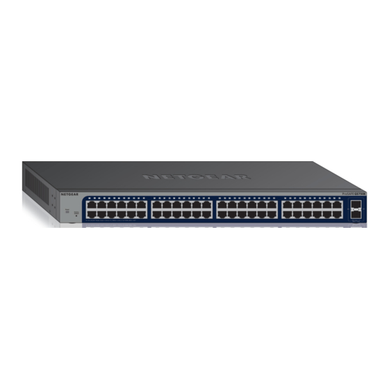
Introduction This hardware installation guide is for the NETGEAR GS750E 48-Port Gigabit Smart Managed Plus Switch with two SFP ports. The GS750E provides forty-eight 10/100/1000M BASE-T RJ-45 copper ports with two dedicated 100 Mb or 1 Gb SFP fiber ports. The switch can be mounted in a rack or on a desktop. -
Page 5: Overview
IP scanner utility. Note The configuration utility runs on Windows-based computers. Visit netgear.com/support/product/PCU to download the utility to configure your switch. After discovery, you can configure the switch using the web management interface or the configuration utility for basic or advanced setup. -
Page 6: Safety Instructions And Warnings
Active flow control to minimize packet loss and frame drops. • Half-duplex backpressure control. • NETGEAR green power-saving features: Energy efficiency mode that fully conforms to the IEEE802.3az standard Per-port automatic change to a lower power mode when the port link is down Safety Instructions and Warnings Use the following safety guidelines to ensure your own personal safety and to help protect your system from potential damage. - Page 7 Any device that is located outdoors and connected to this product must be properly grounded and surge protected. To the extend permissible by applicable law, failure to follow these guidelines can result in damage to your NETGEAR product, which might not be covered by NETGEAR’s warranty. • Observe and follow service markings: Do not service any product except as explained in your system documentation.
- Page 8 48-Port Gigabit Ethernet Smart Managed Plus Switch electrical ratings label. The voltage and current rating of the cable must be greater than the ratings marked on the product. • To help prevent electric shock, plug the system and peripheral power cables into properly grounded electrical outlets.
-
Page 9: Chapter 2 Hardware Overview
Hardware Overview This chapter describes the switch hardware features. The chapter includes the following sections: • Front Panel • Back Panel • LEDs • Switch Hardware Interfaces... -
Page 10: Front Panel
48-Port Gigabit Ethernet Smart Managed Plus Switch Front Panel The GS750E switch provides forty-eight 10/100/1000M BASE-T RJ-45 ports. The following figure shows the front panel. Figure 1. Front panel Number Description Power LED (see LEDs on page 10) Recessed Factory Defaults button... -
Page 11: Switch Hardware Interfaces
48-Port Gigabit Ethernet Smart Managed Plus Switch Table 1. Front panel LEDs Description Power LED Solid green. The device is powered on. Off. Power is not supplied to the device. RJ-45 LEDs 1–48. Off. No link is established. These LEDs indicate Solid green. -
Page 12: Factory Defaults Button
48-Port Gigabit Ethernet Smart Managed Plus Switch Factory Defaults Button The switch provides a Factory Defaults button on the front panel so that you can return the switch to its factory default settings, causing all custom settings to be erased. To return the switch to its factory default settings: Insert a device such as a straightened paper clip into the opening. -
Page 13: Chapter 3 Installation
Installation This chapter describes the installation procedures for the switch. Switch installation involves the steps described in the following sections: • Step 1: Prepare the Site • Step 2: Protect Against Electrostatic Discharge • Step 3: Unpack the Switch • Step 4: Install the Switch •... -
Page 14: Step 1: Prepare The Site
48-Port Gigabit Ethernet Smart Managed Plus Switch Step 1: Prepare the Site Before you install the switch, make sure that the operating environment meets the site requirements that are listed in the following table. Table 2. Site requirements Characteristics Requirements Mounting Desktop installations. -
Page 15: Step 3: Unpack The Switch
48-Port Gigabit Ethernet Smart Managed Plus Switch • When unpacking a static-sensitive component from its shipping carton, leave it in the antistatic package until you are ready to install it. Just before unwrapping the antistatic package, discharge static electricity from your body. •... -
Page 16: Step 4: Install The Switch
Rubber footpads for tabletop installation • Installation guide If any item is missing or damaged, contact your local NETGEAR reseller for replacement. Step 4: Install the Switch You can install the switch in a standard 19-inch (48.26-centimeter) network equipment rack or on a flat surface. -
Page 17: Install The Switch On A Flat Surface
48-Port Gigabit Ethernet Smart Managed Plus Switch Align the mounting holes in the brackets with the holes in the rack, and insert two pan-head screws with nylon washers through each bracket and into the rack. Tighten the screws with a No. 2 Phillips screwdriver to secure mounting brackets to the rack. Figure 4. -
Page 18: Step 6: Check The Installation
48-Port Gigabit Ethernet Smart Managed Plus Switch Note Contact your NETGEAR reseller to purchase these modules. If you do not want to install an SFP module, skip this procedure. To install an SFP transceiver module: Insert the transceiver into the SFP port. -
Page 19: Step 7: Apply Power And Check The Leds
(which requires a Windows-based computer) for very basic setup. For more information about managing the switch, see the installation guide and the user manual, which you can download from downloadcenter.netgear.com. Note The switch’s default IP address is 192.168.0.239 and its default subnet mask is 255.255.255.0. -
Page 20: Chapter 4 Desktop Switching
Desktop Switching The switch is designed to provide flexibility in configuring network connections. The switch can be used as your only network traffic-distribution device or with 10 Mbps, 100 Mbps, and 1 Gbps hubs, routers, and switches. You can use the switch as a desktop switch to build a small network that provides up to 1 Gbps access to a file server. -
Page 21: Chapter 5 Troubleshooting
Troubleshooting This chapter provides information about troubleshooting the switch. The chapter includes the following sections: • Troubleshooting Chart • Additional Troubleshooting Suggestions... -
Page 22: Troubleshooting Chart
48-Port Gigabit Ethernet Smart Managed Plus Switch Troubleshooting Chart The following table lists symptoms, possible causes, and possible solutions for problems that might occur. Table 3. Troubleshooting chart Symptom Possible Cause Possible Solution Power LED is off. Power is not supplied to the Check the power cable connections at the switch switch. - Page 23 Switch integrity. If necessary, verify the integrity of the switch by resetting it. To reset the switch, disconnect the AC power from the switch and then reconnect the AC power. If the problem continues, contact NETGEAR technical support. For more information, visit the support website at support.netgear.com.
Need help?
Do you have a question about the GS750E and is the answer not in the manual?
Questions and answers