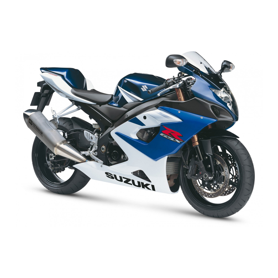
Suzuki GSX-R1000 Service Manual
Hide thumbs
Also See for GSX-R1000:
- Service manual (642 pages) ,
- Service manual (460 pages) ,
- Service manual (525 pages)
Table of Contents
Advertisement
Quick Links
Download this manual
See also:
Service Manual
Advertisement
Table of Contents
Troubleshooting

Summary of Contents for Suzuki GSX-R1000
- Page 1 GSX-R1000 Service Manual *99500-39271-03E* * 9 9 5 0 0 - 3 9 2 7 1 - 0 3 E *...
- Page 2 System and Fuel System be thoroughly reviewed before any type of service work is performed. Further information concerning the EPA emission regulations and U.S. Suzuki’s emission control program can be found in the U.S. SUZUKI EMISSION CONTROL PROGRAM MANUAL/SERVICE BULLETIN.
- Page 4 SUPPLEMENTS GSX-R1000K6 WIRING DIAGRAM...
- Page 51 2-30 PERIODIC MAINTENANCE CHASSIS BOLTS AND NUTS Tighten initially at 1 000 km (600 miles, 2 months) and every 6 000 km (4 000 miles, 12 months) thereafter. Check that all chassis bolts and nuts are tightened to their specified torque. (Refer to page 2-31 for the loca- tions of the following nuts and bolts on the motorcycle.) Item N•m...
-
Page 373: Reassembly And Installation
8-44 CHASSIS REASSEMBLY AND INSTALLATION Reassemble and install the rear wheel in the reverse order of removal and disassembly. Pay attention to the following points: Left Right 100 N·m (10.0 kgf-m, 72.5 lb-ft) 35 N·m 60 N·m (3.5 kgf-m, 25.5 lb-ft) (6.0 kgf-m, 43.5 lb-ft) E-02, 19, 24 25 N·m... - Page 376 CHASSIS 8-47 • Tighten the sprocket mounting nuts to the specified torque. Rear sprocket nut: 60 N·m (6.0 kgf-m, 43.5 lb-ft) NOTE: Stamped mark A on the sprocket should face outside. • Install the collar 2. BRAKE DISC • Apply THREAD LOCK to the disc bolts and tighten them to the specified torque.
- Page 455 9-36 ELECTRICAL SYSTEM HEADLIGHT BEAM ADJUSTMENT • Adjust the headlight beam. NOTE: * Use a screw driver + for adjuster A, B and C. * To adjust the headlight beam, adjust the beam horizontally first, then adjust vertically. A: Horizontal adjuster (Low beam) B: Vertical adjuster (Low beam) C: Horizontal adjuster (High beam) D: Vertical adjuster (High beam)
- Page 508 SERVICING INFORMATION 10-47 CHASSIS N·m kgf-m lb-ft ITEM Steering stem head nut 65.0 Steering stem lock-nut 65.0 Steering damper bolt and nut 16.5 Front fork upper clamp bolt 16.5 Front fork lower clamp bolt 16.5 Front fork cap bolt 16.5 Front fork inner rod lock-nut 21.0 Front fork damper rod bolt...
- Page 532 GSX-R1000K6...
-
Page 533: Specifications
SPECIFICATIONS DIMENSIONS AND DRY MASS Overall length ..................2 030 mm (79.9 in) Overall width..................710 mm (28.0 in) Overall height ..................1 130 mm (44.5 in) Wheelbase ..................1 405 mm (55.3 in) Ground clearance................130 mm (5.1 in) Seat height .................. -
Page 534: Service Data
SERVICE DATA VALVE + VALVE GUIDE Unit: mm (in) ITEM STANDARD LIMIT Valve diam. — (1.18) — (0.94) Valve clearance (when cold) 0.10 – 0.20 — (0.004 – 0.008) 0.20 – 0.30 — (0.008 – 0.012) Valve guide to valve stem 0.010 –... - Page 535 ITEM STANDARD LIMIT Camshaft runout 0.10 — (0.004) Cam chain pin (at arrow “3”) 14th pin — Cylinder head distortion 0.20 — (0.008) CYLINDER + PISTON + PISTON RING Unit: mm (in) ITEM STANDARD LIMIT Compression pressure 1 300 – 1 700 kPa 1 000 kPa (13 –...
-
Page 536: Oil Pump
CONROD + CRANKSHAFT Unit: mm (in) ITEM STANDARD LIMIT Conrod small end I.D. 15.010 – 15.018 15.040 (0.5909 – 0.5913) (0.5921) Conrod big end side clearance 0.10 – 0.20 0.30 (0.004 – 0.008) (0.012) Conrod big end width 19.95 – 20.00 —... - Page 537 CLUTCH Unit: mm (in) ITEM STANDARD LIMIT Clutch lever play 10 – 15 — (0.4 – 0.6) Clutch release screw 1/2 turn back — Drive plate thickness 2.72 – 2.88 2.42 No. 1, 2 and 3 (0.107 – 0.113) (0.095) Drive plate claw width 13.85 –...
- Page 538 THERMOSTAT + RADIATOR + FAN + COOLANT ITEM STANDARD/SPECIFICATION NOTE Thermostat valve opening temper- Approx. 82 °C (180 °F) — ature Thermostat valve lift 8 mm (0.31 in) and over at 95 °C (203 °F) — ECT sensor resistance 20 °C Approx.
- Page 539 FI SENSORS ITEM SPECIFICATION NOTE CMP sensor resistance 0.9 – 1.7 kΩ CMP sensor peak voltage 0.5 V and more When cranking 142 – 194 Ω CKP sensor resistance CKP sensor peak voltage 0.5 V and more When cranking IAP sensor input voltage 4.5 –...
-
Page 540: Throttle Body
THROTTLE BODY ITEM SPECIFICATION Bore size 44 mm I.D. No. 41G1 (For E-33), 41G0 (For the others) Idle r/min 1 150 ± 100 r/min Fast idle r/min 1 400 – 2 000 r/min (When cold engine) Throttle cable play 2.0 – 4.0 mm (0.08 –... - Page 541 WATTAGE Unit: W STANDARD/SPECIFICATION ITEM E-03, 28, 33 Others ← Headlight ← ← Position/Parking light 5 × 2 ← Brake light/Taillight ← Turn signal light 21 × 4 ← License plate light ← Combination meter light ← Turn signal indicator light ←...
- Page 542 ITEM STANDARD LIMIT Wheel rim runout Axial — (0.08) Radial — (0.08) Wheel rim size Front 17 M/C × MT 3.50 — Rear 17 M/C × MT 6.00 — Wheel axle runout 0.25 Front — (0.010) 0.25 Rear — (0.010) TIRE ITEM STANDARD...
- Page 543 (8.86) Front fork oil level (without spring, — outer tube fully compressed) (3.98) Front fork oil type SUZUKI FORK OIL L01 or an equivalent fork oil — Front fork oil capacity (each leg) 510 ml — (17.2/17.9 US/Imp oz) Front fork spring adjuster 4 th groove from top —...
- Page 544 BATTERY HOLDER CUSHION RUBBER INSTALLATION Forward – 13 –...
- Page 547 Prepared by 2005 Part No. 99500-39271-03E Printed in U.S.A.
- Page 548 Printed in USA K5 K6...


Need help?
Do you have a question about the GSX-R1000 and is the answer not in the manual?
Questions and answers