
Related Manuals for LEYBOLD LV 140


Summary of Contents for LEYBOLD LV 140
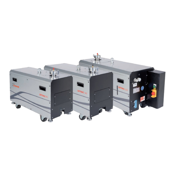
- Page 1 LEYVAC LV 80, LV 140, LV 250 Dry Compressing Vacuum Pumps Operating Instructions 300407956_002_C1 Part Numbers 115080V15 / 30 / 35 / 40 115140V15 / 30 / 35 / 40 115250V15 / 30 / 35 / 40...
-
Page 2: Table Of Contents
Standard- and C-Type Pumps 3.6.2 CC-Type Pumps 3.6.3 Checking the Direction of Rotation 3.6.4 Connecting an external Frequency Converter Mounting Accessories 3.7.1 Roots Pump Adapter 3.7.2 Non-return Valve and Silencers 3.7.4 Gas Ballast Kit (option) 300407956_002_C1 - 01/2017 - © Leybold... - Page 3 Purge Gas Pressure and Flow Regulator Cooling Water Piping Coolant Level Troubleshooting Pump Malfunctions 6.1.1 Malfunctions with CC-type Pumps Malfunctions with Frequency Converter Operations (option) Waste Disposal EC Declaration of Conformity Declaration of Contamination Original installation and operating instructions. 300407956_002_C1 - 01/2017 - © Leybold...
- Page 4 Operating Instructions and follow the information so as to ensure optimum and safe working right from the start. The Leybold LEYVAC has been designed for safe and efficient operation when used properly and in accordance with these Operating Instructions. It is...
-
Page 5: Important Safety Information
Connect and disconnect the mains plug only in deenergized condition. Hot Surface Do not touch. Allow this area to cool before servicing. Burn hazard Hot Surface inside. Do not touch, wear protective equipment. 300407956_002_C1 - 01/2017 - © Leybold... - Page 6 Overhead load Transport the pump only secured with a forklift. Only qualified personnel are allowed to unload and lift the pump. When elevating the pump, no personnel should be under the object. 300407956_002_C1 - 01/2017 - © Leybold...
-
Page 7: Mechanical Hazards
Alternatively use two nylon slings as hoisting devices. Be careful not to overturn the pump when pushing or pulling the pump sideways. 300407956_002_C1 - 01/2017 - © Leybold... -
Page 8: Electrical Hazards
(lockout/tagout) the equipment. Always operate the pump with a properly connected protective earth conductor and make sure that the motor casing is closed. 300407956_002_C1 - 01/2017 - © Leybold... -
Page 9: Thermal Hazards
Heated water can cause burns. Never remove the oil-fill or oil-drain plugs while the pump is running. There exists the risk of suffering burns. Always wear protective gloves and protective goggles also for protection against the oil. 300407956_002_C1 - 01/2017 - © Leybold... -
Page 10: Hazards Caused By Materials And Substances
For this see Section 5.1 Service at Leybold. Leybold is not in a position to perform servicing (repairs) and waste disposal of radioactively contaminated pumps. Both needs to be ensured from the side of the user. -
Page 11: Ignition Risk
Technical Data. In other operating modes and with other equipment, higher values must be expected. Make sure that suitable protection measures are taken to protect your hearing. We recommend to wear hearing protectors (earmuffs), if local noise levels exceed mandatory limits. 300407956_002_C1 - 01/2017 - © Leybold... -
Page 12: Dangers In Connection With Safety-Related Measures And Precautions
In the case of wet processes we recommend the installation of liquid separators, upstream and downstream of the pump so as to avoid the influx of liquid into the pump. 300407956_002_C1 - 01/2017 - © Leybold... - Page 13 Maximum cooling water pressure: 7 bar. When exceeded, there is the risk of leaks. Pressures given in bar or mbar are absolute values. If exceptionally a gauge pressure is meant, a “g” is added (bar(g)). 300407956_002_C1 - 01/2017 - © Leybold...
-
Page 14: Description
Description Fig. 1.1 LEYVAC LV 80; LEYVAC LV 140 and LV 250 similar Description Pump Module Members of the LEYVAC vacuum pump family are of the dry compressing single stage screw vacuum pump type. All LV models are positive displace- ment rotary pumps. - Page 15 8. Shock-absorping Pad 16. High Pressure Side Plate 25. N Pressure Gauge Fig. 1.2 LEYVAC LV 80 Pump Configuration; LEYVAC LV 140 and LV 250 similar 1. Cooling Water Inlet 2. Cooling Water Inlet of Motor 3. Cooling Water Outlet of Motor 4.
- Page 16 The purge gas piping can be divided into two sets of pipe lines. Rotor Purge 24 V DC Purge Gas Shaft Seal Purge LEYVAC LV 80 / 140 / 250 LEYVAC LV 80 / 140 Fig. 1.4b Purge Gas System (schematic) 300407956_002_C1 - 01/2017 - © Leybold...
- Page 17 Refer to the Technical Data Section for adjusting process- dependent purge gas pressures. CC-type pumps are additionally equipped with an EMO at the controller box to enable the user to turn off the pump in case of an emergency. 300407956_002_C1 - 01/2017 - © Leybold...
- Page 18 LEYVAC LV 140 60 Hz Pump Speed Air 50 Hz Pump Speed Air 50 Hz Power Air 60 Hz Power Air Inlet Pressure [mbar] 0.001 0.01 Fig. 1.7 Pumping Speed Curves for LEYVAC LV 140 300407956_002_C1 - 01/2017 - © Leybold...
-
Page 19: Supplied Equipment
Fig. 1.8a Permissible gas inlet temperature as function of the inlet pressure Supplied Equipment Check if all the parts attached are complete. When there is any damage, or when components are missing, contact us immediately. All LEYBOLD vacu- um pumps are equipped with: Operating Instructions ■... -
Page 20: Technical Data
300 kg (C & CC) 320 kg (C & CC) 340 kg (C & CC) Dimensions in mm (L x W x H) 814×375×550 895×400×567 1051×425×537 Water Water connection RC 3/8" Water temperature +15 – 30 °C 300407956_002_C1 - 01/2017 - © Leybold... - Page 21 Flow (normally ambient air) 80 Nl / min Fig. 1.9 Dimensional Drawings Fig. 1.10 Dimensions and Exhaust Arrangements Modell G (CC-type) LV 80 814 (984) LV 140 895 (1065) LV 250 1051 (1224) Dimensions in mm 300407956_002_C1 - 01/2017 - © Leybold...
-
Page 22: Ordering Information
115005A01 Check valve spring loaded (for noise reduction) 115005A02 RUVAC Adapter for Wx(U)501 and WH700 onto LV 80 / LV 140 115005A03 RUVAC Adapter Disc for WX1001 onto LV 140 115005A04* RUVAC Adapter for Wx(U)501 / WH700 onto LV 250... -
Page 23: Transport And Storage
The pumps are supplied filled with PFPE or synthetic oil. For this reason they should, while being transported or shipped, not be subjected to tilting by more than 10° with respect to the horizontal axis. Store the pumps only horizontally standing on their feet. 300407956_002_C1 - 01/2017 - © Leybold... - Page 24 If there is the danger of frost, the cooling water for the external water cir- cuit must be drained, see Section 4.4 Removing from Service Temperature -10 to +60 °C Coolant mixture 30% glycol Storage site Maximum atmospheric humidity < 95 %, non-condensing 300407956_002_C1 - 01/2017 - © Leybold...
-
Page 25: Installation
The oil levels of both, the gear box and the low pressure side, should be between 1/2 - 2/3 of the oil level glass. If the level is below 1/2, lubricant should be added. See the Maintenance section for further information. 300407956_002_C1 - 01/2017 - © Leybold... -
Page 26: Conforming Use
Pumping of gases and vapours for which the materials of the pump are not ■ suited, consult Leybold. For a list of materials in contact with the process gases, see Section 1.3 Technical Data. Pumping of substances and mixtures (gases, liquids and solids) which are ■... - Page 27 Conversions, manipulations and maintenance work by persons not author- ■ ised by Leybold. Accessories which have not been specified by Leybold may only be used ■ after approval by Leybold. The non-conforming use of pump and accessories may result in severe WARNING injury or damage to the components.
-
Page 28: Connecting The Intake And Exhaust Lines
When choosing and installing the vacuum pumps for harsh processes or for processes of special applications, like harsh furnace process, toxic or explo- sive gas process, please check in advance with the engineers of Leybold; when necessary, we suggest installing a trap at the pump inlet or outlet port to prevent any safety accidents. - Page 29 In order to prevent deposits in the exhaust lines it may be necessary to heat the exhaust lines. Run the exhaust line only by way of a fixed installation to the outside and/or connected to a silencer. 300407956_002_C1 - 01/2017 - © Leybold...
-
Page 30: Connecting Cooling Water
If there is the danger of frost, you may use a water glycol mixture of up to 30 %. When using DS water/deionised water (softened or fully desalinated water) check whether cooling system, water and materials used are suitable. For this please con- sult us. 300407956_002_C1 - 01/2017 - © Leybold... -
Page 31: Purge Gas Piping
1.5 to 2 bar (g) (0.15 – 0.2 MPa (g)). As Leybold vacuum pumps can be used for a variety of processes the amount of sediments thus produced will also be different. In order to reduce... -
Page 32: Electrical Connection
) Relay (A) Main fuse Cable Size (mm ) Relay (A) LV 80 LV 140 LV 250 Recommended rated current of main fuse and cable sizes The voltage for the power supply should be kept within ±10% of the rating voltage. 300407956_002_C1 - 01/2017 - © Leybold... -
Page 33: Standard- And C-Type Pumps
Refer to the table below for the trigger temperatures. Electric Device (cable) Status Action Temperatures Reset Temperatures Motor Thermal Switch (black) 90 °C 50 – 60 °C Casing Thermal Switch (white) 85 °C 45 – 65 °C 300407956_002_C1 - 01/2017 - © Leybold... - Page 34 Supply 9 - 30V Sensor < 5mA (optional) Purge Gas 24V DC – Control Unit prov. by Pump customer LEYVAC LV 80 / 140 / 250 Fig. 3.5 Main and Control Circuit Wiring (without frequency converter; non-CC-pumps) 300407956_002_C1 - 01/2017 - © Leybold...
-
Page 35: Cc-Type Pumps
CC-type pumps are equipped with a regulating transformer for dual voltages. Select the corresponding feed terminals A1 at the regulating transformer TR1 depending on the voltage range used: 380 – 420V: terminal 415V; 420 – 460V: terminal 380V. 300407956_002_C1 - 01/2017 - © Leybold... - Page 36 * For pump operation in 460 V / 60 Hz nets the input connection of Transformer (A1) has to be changed by trained staff from 415 V to 460 V. Output connection of Transformer (A2) stays unchanged. 300407956_002_C1 - 01/2017 - © Leybold...
-
Page 37: Checking The Direction Of Rotation
Enclosed with the frequency converters delivered by Leybold is a copy of the instructions for commisioning the Yaskawa V1000. This frequency converter shows an integrated mains filter and perfectly matches the pump. - Page 38 “M“ th e f u nc t ion of anal og i npu t A 2 is m u l ti- f un c ti on inp u t. Fig. 3.8 Wiring of the main and control circuits for LEYVACs w/ external frequency converter 300407956_002_C1 - 01/2017 - © Leybold...
- Page 39 The potential equalisation conductor must be connected as depicted in Fig. 3.9. After connecting the motor and every time you alter the wiring, check the direction of rotation (cf. Section 3.6.3 for more information). 300407956_002_C1 - 01/2017 - © Leybold...
-
Page 40: Mounting Accessories
Before the adapter can be mounted the stainless steel pump inlet must be removed. Keep this gasket and the 4 screws for re-use. The RUVAC adapter comes with 4 substitute screws; the RUVAC comes completely with bolts, washers, nuts and gasket. 300407956_002_C1 - 01/2017 - © Leybold... - Page 41 Supplied Equipment Adapter ■ 4 hexagon socket screws M 8x25 ■ O-ring 80x5, 4 stud bolts M 12x50, 8 washers A 13, 8 nuts M 12 (for fas- ■ tening the RUVAC) 300407956_002_C1 - 01/2017 - © Leybold...
-
Page 42: Non-Return Valve And Silencers
(cf. Section 1.4). With a horizontal version the supplied elbow can be used; in this case the serviceable silencer must be attached, to ensure that the ball valve is the lowest point of the exhaust system. 300407956_002_C1 - 01/2017 - © Leybold... - Page 43 At the upper tee remove the blank flange from the shaft seal purge gas pipe. Connect all pipes and tees as shown above. Make sure to insert the orifice plate into the riser of the lower tee. 300407956_002_C1 - 01/2017 - © Leybold...
-
Page 44: Gas Ballast Kit (Option)
When pumping dangerous, flammable, or toxic gases the gas ballast kit of the LEYVAC LV 250 must not be used! The gas ballast conversion kit contains all of the necessary modification parts. Only C- and CC-type pumps: Remove the side cover. 300407956_002_C1 - 01/2017 - © Leybold... - Page 45 Systematically check for leaks after the installation, and before starting the pump system. Only C- and CC-type: Conduct a leak test before re-fitting the cover. Check the gas ballast filter contamination on a regular basis. 300407956_002_C1 - 01/2017 - © Leybold...
-
Page 46: Operation
Turn on purge gas supply. Adjust the pressure slowly to 1.5 bar (0.15 MPa), then lock the knob. The manometer might be damaged while the purge gas supply pressure is too large. 300407956_002_C1 - 01/2017 - © Leybold... -
Page 47: Pumping Of Monoatomic Gas
4.1.1 Pumping of monoatomic Gas Due to the higher adiabatic exponent K with monoatomic gases (e.g. argon) and resulting higher compression temperatures please consult with the corre- sponding customer service before pumping these gases to evaluate your application. 300407956_002_C1 - 01/2017 - © Leybold... -
Page 48: Stop Pump
If during longer downtimes the system shall remain conditioned for a rapid pumpdown, we recommend to vent the system with dry nitrogen to atmos- pheric pressure and maintain it in this condition without opening it. 300407956_002_C1 - 01/2017 - © Leybold... -
Page 49: Removing From Service
Blow out the cooling water coils with compressed air or Nitrogen (max. 4 bar). Blow into the cooling water inlet port only. Drain the lubricant (PFPE or synthetic oil) out of the pump (cf. Fig. 5.1). Drain lubricant 300407956_002_C1 - 01/2017 - © Leybold... - Page 50 Unscrew the drain plug. Tools and bucket must be clean so as not to further contaminate the lubricant. Screw the drain plug with the sealing ring back in, wipe off any dripped lubri- cant from the casing. 300407956_002_C1 - 01/2017 - © Leybold...
-
Page 51: Maintenance
In clean processes, you may increase the maintenance intervals; in harsh processes, you may have to decrease them. We recommend a service contract with Leybold. We recommend to inspect the pump system and all components after approximately 6 months under the process conditions. The inspection of the components shall let corrosion attacks become apparent at an early stage and indicate possible deposits of process dust. - Page 52 Disposal of process byproducts, lubricating oil, vacuum grease and other wastes must be in strict accordance with all local and national environmen- tal and safety regulations. For further info see Section 7 Waste Disposal. 300407956_002_C1 - 01/2017 - © Leybold...
-
Page 53: Exchanging The Lubricant
When the pump has become warm during operation the casing and the oil temperature may exceed 80 °C. Leave the pump to cool down. Always wear protective gloves also to pro- tect yourself against aggressive residues in the lubricant. 300407956_002_C1 - 01/2017 - © Leybold... -
Page 54: Exhaust Piping Connector
Fill in new oil at a pump temperature of 15 ºC to 25 ºC. ■ Make sure to use the right kind of oil and according to Leybold’s sugges- ■ tion. Only use Leybold authorized vacuum oil and re-supply the new oil. -
Page 55: Purge Gas Pressure And Flow Regulator
FULL and LOW. If the level is really low, additionally fill in coolant directly into the main cooling circuit (cf. Fig. 5.2). The capacity of the main cooling circuit and the expansion vessel is approx. 5 litres. 300407956_002_C1 - 01/2017 - © Leybold... -
Page 56: Troubleshooting
To remove an alarm or reset a fault, trace the cause, remove it and reset the frequency converter by pushing the Reset key on the operator or cycling the power supply. This lists up the most important alarms and faults only. 300407956_002_C1 - 01/2017 - © Leybold... - Page 57 50% of the frequency converters rated short circuits or broken insulation. Replace any output current. broken parts. Cable or motor insulation is broken. Reduce the carrier frequency. Excessive stray capacitance at frequen- cy converter output. 300407956_002_C1 - 01/2017 - © Leybold...
- Page 58 Drive The load is too heavy. Check the load. Overload Too much torque at low speed. The overload capability is reduced at low speeds. Reduce the load or increase the fre- quency converter size. 300407956_002_C1 - 01/2017 - © Leybold...
-
Page 59: Waste Disposal
Waste oil from vacuum pumps must not be mixed with other substances or materials. Waste oil from vacuum pumps (Leybold oils which are based on mineral oils) which are subject to normal wear and which are contaminated due to the influence of oxygen in the air, high temperatures or mechanical wear must be disposed of through the locally available waste oil disposal system. -
Page 60: Ec Declaration Of Conformity
EC Declaration of Conformity 300407956_002_C1 - 01/2017 - © Leybold... -
Page 61: Declaration Of Contamination
Person to contact: Calibration: Factory-calibr. Phone : Fax: Quality test certificate DIN 55350-18-4.2.1 End user: A. Description of the Leybold product: Failure description: Material description : Catalog number: Additional parts: Serial number: Application-Tool: Type of oil (ForeVacuum-Pumps) : Application- Process: B. - Page 62 Sales and Service Germany America Great Britain Leybold Japan Co., Ltd. Tsukuba Technical Service Center 1959, Kami-yokoba Leybold UK LTD. Leybold GmbH Tsukuba-shi, Ibaraki-shi 305-0854 Unit 9 Sales, Service, Support Center (3SC) Japan Silverglade Business Park Bonner Strasse 498 Leybold USA Inc.
Need help?
Do you have a question about the LV 140 and is the answer not in the manual?
Questions and answers