Sign In
Upload
Download
Table of Contents
Contents
Add to my manuals
Delete from my manuals
Share
URL of this page:
HTML Link:
Bookmark this page
Add
Manual will be automatically added to "My Manuals"
Print this page
×
Bookmark added
×
Added to my manuals
Manuals
Brands
Steamist Manuals
Portable Generator
HC-9
Owner's manual
Steamist HC-9 Owner's Manual
Heavy commercial steambath generator
Hide thumbs
Also See for HC-9
:
Owner's manual
(14 pages)
,
Owner's manual
(14 pages)
1
Table Of Contents
2
3
4
5
6
7
8
9
10
11
12
13
14
15
16
page
of
16
Go
/
16
Contents
Table of Contents
Bookmarks
Table of Contents
Table of Contents
Important Steam Bath Safety Guidelines
Warning Sign Installation
Warning Sign
III. Pre-Installation
Pre-Installation
IV. Rough-In
Rough-In
Installation
Digital Command Center Installation
Digital Commercial Control Package Operation
Figure 8 - Manager and User Controls
Programming Examples
Specifications Chart
Limited Warranty
Advertisement
Quick Links
1
Table of Contents
2
Digital Command Center Installation
3
Digital Commercial Control Package Operation
4
Figure 8 - Manager and User Controls
5
Programming Examples
6
Specifications Chart
Download this manual
Owners Manual
®
®
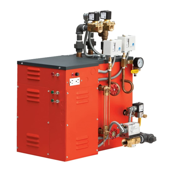
Heavy Commercial Steambath Generator
Models: HC-9 thru HC-24 with DCCP Control
05/13
- 1 -
Pub. No. 601-C
Table of
Contents
Previous
Page
Next
Page
1
2
3
4
5
Advertisement
Table of Contents
Need help?
Do you have a question about the HC-9 and is the answer not in the manual?
Ask a question
Questions and answers
Related Manuals for Steamist HC-9
Iron Steamist HC-9 Owner's Manual
Heavy commercial steambath generator (14 pages)
Inverter Steamist HC-9 Owner's Manual
Steambath generator (14 pages)
Portable Generator Steamist HC-24 Owner's Manual
Heavy commercial steambath generator (16 pages)
Portable Generator Steamist TSG-10 Installation Instructions
Steambath generator (4 pages)
Portable Generator Steamist SM-11 Installation Instructions
Steambath generators (4 pages)
Portable Generator Steamist SM-4 Installation Instructions
Steambath generators (4 pages)
Portable Generator Steamist SM-11 Electrical Installation Instructions
Steambath generator (4 pages)
This manual is also suitable for:
Hc-24
Table of Contents
Print
Rename the bookmark
Delete bookmark?
Delete from my manuals?
Login
Sign In
OR
Sign in with Facebook
Sign in with Google
Upload manual
Upload from disk
Upload from URL


Need help?
Do you have a question about the HC-9 and is the answer not in the manual?
Questions and answers