
Related Manuals for Zte ZXCLOUD iBOX CT320


Summary of Contents for Zte ZXCLOUD iBOX CT320
-
Page 1: Quick Start Guide
ZXCLOUD iBOX CT320 Quick Start Guide ZTE CORPORATION NO. 55, Hi-tech Road South, ShenZhen, P.R.China Postcode: 518057 Tel: +86-755-26770800 Fax: +86-755-26770801 URL: http://support.zte.com.cn E-mail: 800@zte.com.cn... -
Page 2: Legal Information
ZTE CORPORATION or its licensors may have current or pending intellectual property rights or applications covering the subject matter of this document. Except as expressly provided in any written license between ZTE CORPORATION and its licensee, the user of this document shall not acquire any license to the subject matter herein. -
Page 3: Table Of Contents
Contents 1 Introduction to the Cloud Terminal ............4 1.1 FCC Statement ..................4 1.2 Safety Precautions ................. 5 1.3 Overview of the Cloud Terminal..............6 1.4 Features of the Cloud Terminal ..............6 1.5 Components of the Cloud Terminal............... 7 1.6 Connecting the Cloud Terminal to Peripherals .......... -
Page 4: Introduction To The Cloud Terminal
Introduction to the Cloud Terminal 1.1 FCC Statement FCC Statement This equipment has been tested and found to comply with the limits for a Class B digital device, pursuant to part 15 of the FCC Rules. These limits are designed to provide reasonable protection against harmful interference in a residential installation. -
Page 5: Safety Precautions
1.2 Safety Precautions Installation Use the power adapter delivered with the ZXCLOUD iBOX CT320 (hereinafter referred to as � the cloud terminal). Use of any other power adapter can damage the cloud terminal or affect its normal operation. Ensure that the electric load of the power sockets or power cables meets the requirements. -
Page 6: Overview Of The Cloud Terminal
1.3 Overview of the Cloud Terminal The ZXCLOUD iBOX CT320 is a thin client without any mechanical components. As a desktop cloud terminal, it has a small size, light weight and requires low power consumption. In addition, it is reliable, easy to use, and energy saving. -
Page 7: Components Of The Cloud Terminal
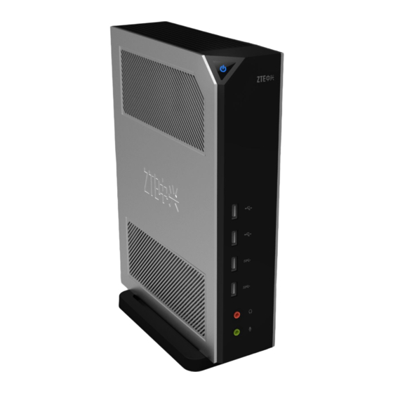
Support for network power supply � The cloud terminal supports the PoE function (purchased separately) which allows power to be supplied to the cloud terminal through Ethernet cables. Therefore, it enables the most flexible deployment with the least cables. Energy-saving �... - Page 8 Figure 2 Front Panel Figure 3 shows the back panel of the cloud terminal.
- Page 9 Figure 3 Back Panel Table 1 provides a description of the components in the cloud terminal. Table 1 Description of the Cloud Terminal Components Component Description rial Power on/off Press this button to turn on or off the cloud terminal. button/power The power indicator lights red when the cloud terminal is being started.
-
Page 10: Connecting The Cloud Terminal To Peripherals
Component Description rial Speaker 16-bit stereo audio output interface with a 3.5 mm aperture. Connects to a headphone or an external audio device. Microphone 8-bit microphone audio input interface with a 3.5 mm aperture. Connects to a microphone. DVI-I interface Connects to any display with a DVI-I interface. - Page 11 1. Install the cloud terminal properly. The cloud terminal can be installed horizontally or vertically on a horizontal workbench (To vertically install the cloud terminal on the workbench, the base delivered with the terminal must be used) or mounted to the back of a display or another concealed location through a bracket (purchased separately).
- Page 12 Figure 4 Connections of the Cloud Terminal to Related Peripherals...
-
Page 13: Turning On/Off The Cloud Terminal
Note: When connecting the cloud terminal to a display, ensure that the input interface of the terminal matches that of the display. If the display is configured with a DVI-I interface, the display can be directly connected to the terminal. If the display is only configured with a VGA interface, the DVI-I to VGA converter delivered with the terminal must be used. -
Page 14: Technical Specifications
1.8 Technical Specifications System Specifications Table 2 ZXCLOUD iBOX CT320 Technical Specifications Parameter Description Intel D2550 dual core 1.86G Hz Memory 2G/4G DDR3 Storage 8G/16G SSD (supporting SATA micro hard disks) Video DVI-I (supporting dual display clone and expansion) Audio... -
Page 15: Packing List
Warranty ZTE CORPORATION provides a 3-year warranty for the cloud terminal and 1-year warranty for the accessories (keyboard, mouse, and power cables). ZTE CORPORATION reserves the right to modify technical specifications in this manual without any notification in advance. 1.9 Packing List... -
Page 16: Logging In To The Operating System Of The Cloud Terminal
2. × marked on this product indicates that there are currently no alternative technologies or components. 3. The product manufactured by ZTE CORPORATION is in compliance with the Measures for the Con- trol of Pollution from Electronic Information Products published by People's Republic of China. - Page 17 Steps 1. Press the power on/off button to start the cloud terminal. After the terminal is started, the login page is displayed, see Figure Figure 5 Login Page Note: The shortcut buttons on the page vary with the actual software installed in the system.
Need help?
Do you have a question about the ZXCLOUD iBOX CT320 and is the answer not in the manual?
Questions and answers