
Related Manuals for Toshiba FT-8009


Summary of Contents for Toshiba FT-8009
- Page 1 FILE NO. 2B0-9901 SERVICE MANUAL CORDLESS TELEPHONE FT-8009 PUBLISHED IN JAPAN, Aug., 1999...
-
Page 2: Table Of Contents
CONTENTS SAFETY PRECAUTIONS ......................1 OPERATING CONTROLS ......................2 ALIGNMENT PROCEDURE ......................3 BLOCK DIAGRAMS ........................7 SCHEMATIC DIAGRAMS ......................9 TROUBLESHOOTING HINTS ....................13 IC AND TRANSISTOR VOLTAGE CHART ................20 SEMICONDUCTOR LEAD IDENTIFICATION ................24 ELECTRICAL PARTS LOCATION ..................... 26 WIRING DIAGRAMS ......................... -
Page 3: Operating Controls
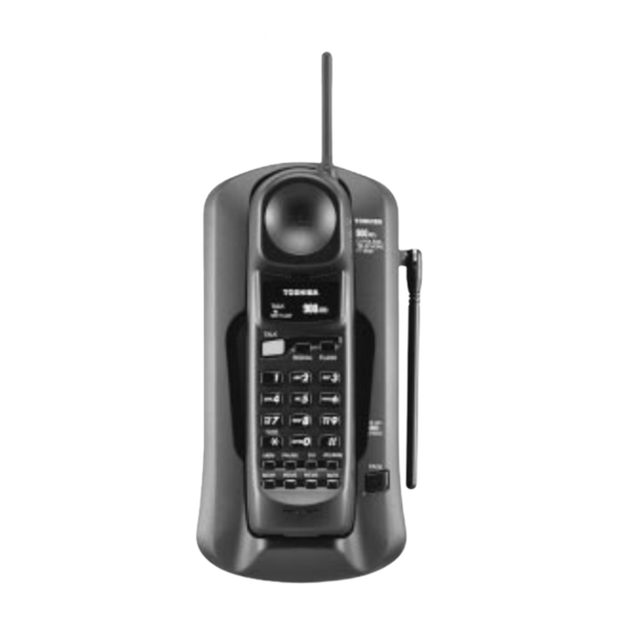
OPERATING CONTROLS HANDSET CONTROLS AND FUNCTIONS Antenna TALK/BATT.LOW LED REDIAL Button FLASH Button TALK Button Dialpad TONE Button VOL/RING Button MEM Button PAUSE Buttons CH Button One-touch dialing Button MUTE Button (MEM1 - MEM3) Rechargeable Battery Pack Charging Contacts (back) BASE UNIT CONTROLS AND FUNCTIONS DC in 9V Jack T-P(TONE-PULSE) Switch... -
Page 4: Alignment Procedure
ALIGNMENT PROCEDURE Base Unit Transmitter Section BASE Unit AF GEN. Test Point Power Connections Meter DC IN TEL Line 1kHz 77.5mV 9V Jack Jack Test Point Frequency Counter AC 120V Adapter 60Hz Deviation Mater Preset a) Connect the base RF unit to the base main unit. b) Set the “TONE / PULSE”... - Page 5 Receiver Section Connections BASE Unit AC Voltmeter RF SG Dummy Load (600-ohm) TEL Line Test Point Jack DC Voltmeter DC IN 9V Jack Terminal AC 120V 60Hz Adapter Preset a) Connect the base RF unit to the base main unit. b) Set the “TONE/PULSE”...
- Page 6 Handset Unit Transmitter Section Connection HANDSET Unit AF GEN. Test Point Power Meter J603 Battery 1kHz 9mV MIC+Pin Connector Test Point Frequency Counter DC Power Supply Deviation Mater DC 3.8V Preset a) Connect the handseet RF unit to the handset main unit. b) Connect DC power supply to battery connector on the handset unit.
- Page 7 Receiver Section Connections HANDSET Unit AC Voltmeter RF SG Dummy Load (150-ohm) J602 Test Point Connector DC Power Supply J603 DC Voltmeter Battery Terminal Connector DC 3.8V Preset a) Connect the handset RF unit to the handset main unit. b) Connect DC power supply to battery connector on the handset unit. c) Turn the DC power supply ON while pressing “...
-
Page 8: Block Diagrams
BLOCK DIAGRAMS Base Unit... - Page 9 Handset...
-
Page 10: Schematic Diagrams
SCHEMATIC DIAGRAMS Base Unit... - Page 11 Handset...
-
Page 12: Troubleshooting Hints
TROUBLESHOOTING HINTS 1. The bell does not ring. See 2. The bell does not ring When the PAGE SW of the & page does not ring. base is pressed, does the ringer on the handset ring? When the TEL SG is joined Check IC4 and TEL network with the base to make bell circuit. - Page 13 2. The bell does not ring & page does not ring. Can the base and handset be See 3. The base and handset connected? cannot be connected. Press handset DIAL key When the key of the handset is Check IC404. while in TALK MODE.
- Page 14 3. The base and handset cannot be connected. Check whether the base Check IC5 and its is able to set in the test peripheral circuit. mode 1. Check the TX POWER Check base RF unit. and the TX FREQUENCY on the base unit. Set the base in the test Check whether there is a Check RT3, R40, R68,...
- Page 15 Set the handset in the Check whether there is a Check RT403, R441, test mode 3, check 250 Hz data waveform at R442, R443, R444, whether deviation of the “MOD” of RF unit. R445 and C453. TX data is app. 8 kHz Dev.
- Page 16 4. Cannot make a phone call (pulse). Can the base and handset See 3. The base and handset be connected? cannot be connected. While in TALK MODE, press Check IC5. dial key of the handset. Check whether square waveform from pin 13 of IC5 is fed.
- Page 17 6. Voice cannot be transmitted to other party (outgoing call). Can the base and handset be See 3. The base and handset connected? cannot be connected. The 1 kHz, 9.0mV sine Check Q404 and its wavefor m i s a p p l i e d t o peripheral circuit.
- Page 18 7. The voice of the caller cannot be heard (incoming call). Can the base and handset be See 3. The base and handset connected? cannot be connected. The 1 kHz, 77.5mV sine Check the base TEL-line waveform is applied to TEL- circuit and REPLAY control line of the base, can the 1 kHz circuit.
-
Page 19: Ic And Transistor Voltage Chart
IC AND TRANSISTOR VOLTAGE CHART Base Unit Unit[V] Unit[V] Ref. No. PIN STBY TALK NOTE Ref. No. PIN STBY TALK NOTE 1.2(AC) 1.2(AC) OPEN 1.8(AC) 1.8(AC) OPEN OPEN OPEN 0-3.2 0-3.2 OPEN OPEN OPEN OPEN OPEN OPEN OPEN OPEN OPEN OPEN OPEN OPEN... - Page 20 Unit[V] Ref. No. PIN STBY TALK NOTE OPEN...
- Page 21 Handset Unit[V] Unit[V] Ref. No. PIN STBY TALK NOTE Ref. No. PIN STBY TALK NOTE 2.0(AC) 0-3.5 2.0(AC) OPEN OPEN IC401 0-0.3 OPEN OPEN OPEN OPEN 0-2.0 0-2.0 0-1.5 0-0.4 0-0.4 0-0.4 1.0-3.0 0-1.8 IC404 1.0-3.0 OPEN 0-3.0 IC403 0-1.0 0-3.0 OPEN 0-3.0...
- Page 22 Unit[V] Unit[V] Ref. No. PIN STBY TALK NOTE Ref. No. PIN STBY TALK NOTE Q412 0-0.5 IC405 0-1.2 0-0.5 0-3.0 IC406 Q401 0-2.0 0-0.8 Q402 0-2.0 0-0.8 0-3.0 Q403 0-2.4 Q404 Q405 Q406 Q407 Q408 Q409 Q410 Q411...
-
Page 23: Semiconductor Lead Identification
SEMICONDUCTOR LEAD IDENTIFICATION Base Unit D6 : MVR3338ST D1 /D4 / D9 / D10 : 1N4148 D3 : HZ33-2 D11 : HZ7A3 D13 : HZ4B1 Anode Cathode Cathode Anode Q1 : 2SC2714 Q7 / Q8 / Q11 : 2SD471 Q2 / Q3 / Q4 / Q6 / Q9 / Q10 : 2SC1623 Q12 : 2SA812(M) B : Base E : Emitter... - Page 24 Handset D407 : HSM88WA D408 : SML-310LT D401 / D402 / D405 / D406 : RLS4148 D403 / D404 : HZK6C Anode Anode Cathode Anode Cathode Cathode Cathode Q401 : 2SC2714 Q402 / Q404 / Q405 / Q406 / Q407 / Q408 / Q409 / Q410 / Q411 / Q412 : 2SC1623 Q403 : 2SA812(M) B : Base...
-
Page 25: Electrical Parts Location
ELECTRICAL PARTS LOCATION Base Unit Main PCB... - Page 26 Handset Main PCB...
-
Page 27: Wiring Diagrams
WIRING DIAGRAMS Base Unit... - Page 28 Handset...
-
Page 29: Exploded View And Mechanical Parts List
EXPLODED VIEWS AND MECHANICAL PARTS LIST Base Unit MAIN PCB ASSY RF MODULE (BASE) ANTENNA... - Page 30 Base Unit LOC. REF. PART NO. DESCRIPTION RC008363 GNBZ442428Z BUTTON, PUSH for FT-8009 RC008314 GNBZ442328Z BUTTON, PUSH for FT-8009BK RC008376 GNBZ442640Z BUTTON, PUSH for FT-8009GR RC008361 GCAS342427Z CASE, BOTTOM for FT-8009 RC008312 GCAS242327Z CASE, BOTTOM for FT-8009BK RC008374 GCAS342639Z CASE, BOTTOM for FT-8009GR...
- Page 31 Handset RF MODULE (HANDSET) MAIN PCB ASSY...
- Page 32 RBLD442208Z BLIND for FT-8009 RC008346 RBLD442400Z BLIND for FT-8009BK RC008384 RBLD442649Z BLIND for FT-8009GR RC008368 GNBZ442524Z BUTTON, FUNCTION for FT-8009 RC008340 GNBZ342334Z BUTTON, FUNCTION for FT-8009BK ABS RC008382 GNBZ442645Z BUTTON, FUNCTION for FT-8009GR ABS RC008366 GCAS342523Z CASE, FRONT for FT-8009...
-
Page 33: Parts List
PARTS LIST PRODUCT SAFETY NOTE : Products marked with a have special characteristics important to safety. Before replacing any of these components, read carefully the product safety notice of this service manual. Don't degrade the safety of the product through important servicing. Symbol Symbol 30 -20+80 0+100... - Page 34 LOC. REF. PART NO. DESCRIPTION RC005202 BCML311045Z CERAMIC M/L (1608) TAPE 0.1UF 16V K B RC008843 BCML313335Z CERAMIC M/L (1608) TAPE 0.033UF 16V K B RC005206 BCML812225Z CERAMIC M/L (1608) TAPE 0.0022UF 50V K B RC005205 BCML811035Z CERAMIC M/L (1608) TAPE 0.01UF 50V K B RC005205 BCML811035Z CERAMIC M/L (1608) TAPE 0.01UF 50V K B...
- Page 35 LOC. REF. PART NO. DESCRIPTION C423 RC005204 BCML811025Z CERAMIC M/L (1608) TAPE 0.001UF 50V K B C424 RC005205 BCML811035Z CERAMIC M/L (1608) TAPE 0.01UF 50V K B C425 RC005224 BCMT813091Z CERAMIC M/L (1608) TAPE 3PF 50V C CJ C426 RC005205 BCML811035Z CERAMIC M/L (1608) TAPE 0.01UF 50V K B C427 RC005211 BCMM811204Z CERAMIC M/L (1608) TAPE...
- Page 36 LOC. REF. PART NO. DESCRIPTION RC002236 BDAY0246003 AX TS 26+ 1N4148 T-77 RC008274 BDAY1084001 MVR3338ST-922 RC002236 BDAY0246003 AX TS 26+ 1N4148 T-77 RC002236 BDAY0246003 AX TS 26+ 1N4148 T-77 RC008886 BDAY0492048 ZENER AX TS 26 + HZ7A3 TD RC008273 BDAY0492036 ZENER AX TS 26 + HZ4B1 TD D401...
- Page 37 LOC. REF. PART NO. DESCRIPTION Q402 RC003031 BDBC1623648 DB-380 2SC1623-L6 T1B Q403 RC008275 BDBA0812695 DB-035 2SA812(M)-M6A T1B Q404 RC003031 BDBC1623648 DB-380 2SC1623-L6 T1B Q405 RC003031 BDBC1623648 DB-380 2SC1623-L6 T1B Q406 RC003031 BDBC1623648 DB-380 2SC1623-L6 T1B Q407 RC003031 BDBC1623648 DB-380 2SC1623-L6 T1B Q408 RC003031 BDBC1623648 DB-380 2SC1623-L6 T1B...
- Page 38 LOC. REF. PART NO. DESCRIPTION RC005256 BRFC164724Z CARBON FIXED CHIP 4.7K 1/16W J TAPING RC005240 BRFC161024Z CARBON FIXED CHIP 1K 1/16W J TAPING RC005283 BRFC162734Z CARBON FIXED CHIP 27K 1/16W J TAPING RC005240 BRFC161024Z CARBON FIXED CHIP 1K 1/16W J TAPING RC005240 BRFC161024Z CARBON FIXED CHIP 1K 1/16W J TAPING RC005241 BRFC161034Z CARBON FIXED CHIP...
- Page 39 LOC. REF. PART NO. DESCRIPTION R418 RC005248 BRFC162234Z CARBON FIXED CHIP 22K 1/16W J TAPING R419 RC005247 BRFC162214Z CARBON FIXED CHIP 220 1/16W J TAPING R420 RC005247 BRFC162214Z CARBON FIXED CHIP 220 1/16W J TAPING R421 RC005241 BRFC161034Z CARBON FIXED CHIP 10K 1/16W J TAPING R422 RC005240 BRFC161024Z CARBON FIXED CHIP...
- Page 40 RC008202 WBXZ342403Z DISPLAY BOX for FT-8009GR RC008223 PLBM442785Z INDEX PAPER PAPER RC004688 PLBB454286Z LABEL:BARCODE PAPER RC004689 PLBB454287Z LABEL:BARCODE PAPER RC008222 UCZZ01218BZ OWNER'S MANUAL RC008372 WCTZ442897Z SHIPPING CARTON BOX for FT-8009 RC008354 WCTZ442425Z SHIPPING CARTON BOX for FT-8009BK RC008385 WCTZ442356Z SHIPPING CARTON BOX for FT-8009GR...
-
Page 41: Assembly Parts List
300X300X400X0.07T RC008353 VNYL3101000 VINYL BAG 100X100X0.1T ASSEMBLY PARTS LIST NOTE: Following part numbers are not available as replacement parts. Order parts necessary for repair or contact the Toshiba Factory Service Center. LOC. REF. PART NO. DESCRIPTION RC008386 AC218BLBA MAIN PCB ASSY, BASE... -
Page 42: Specifications
SPECIFICATIONS MEASUREMENT CONDITIONS 1. Standard Voltage :Portable Unit ..DC 3.8V ± 0.025V :Base Unit ..AC 120V ± 3V 60Hz 2. Temperature ± 5 3. Channel FCC CH Portable(TX Frequency) Base(TX Frequency) 902.052464MHz 925.997470MHz 902.102465MHz 926.047470MHz 902.152465MHz 926.097470MHz 902.202465MHz 926.147470MHz 902.252465MHz 926.197470MHz... - Page 43 BASE UNIT RECEIVER UNIT NOMINAL LIMIT 1. Sensitivity 12 dB SINAD with CCITT Filter -115 < -107 2. Frequency Response (Ref:1kHz) 0.3kHz -2.0 -6.0~+2.0 3.0kHz -5.0 -9.0~-1.0 3. Distortion at 1 mV RF Input < 5 4. S/N ratio at 1 mV RF Input with CCITT Filter 60 <...
- Page 44 PORTABLE UNIT RECEIVER UNIT NOMINAL LIMIT 1. Sensitivity 12 dB SINAD with CCITT Filter -115 < -107 2. Frequency Response (Ref:1kHz) 0.3kHz -2.5 -6.5~+1.5 3.0kHz -4.0 -8.0~0.0 3. Audio Output Level VOL. HIGH 161~322 VOL. MEDIUM 91~181 VOL. LOW 36~72 4.
Need help?
Do you have a question about the FT-8009 and is the answer not in the manual?
Questions and answers