
Related Manuals for SIP 01552

Summary of Contents for SIP 01552
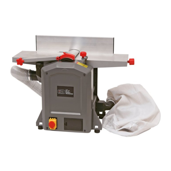
- Page 1 01552 8”x 8” Planer Thicknesser Please read and fully understand the instructions in this manual before operation. Keep this manual safe for future reference.
-
Page 2: Table Of Contents
Table of Contents Product Specifications Page 3 Safety Rules Page 4 Unpacking Page 6 Installation Page 6 Structure and Functions Page 6 Supplementary Safety Instructions Page 7 Operation Regulations Page 9 Maintenance Page 13 Attention Page 13 Assembly Diagram Page 14 Part List Page 15... -
Page 3: Product Specifications
PRODUCT SPECIFICATIONS Motor (Please choose proper power source, voltage and frequency that are shown in the label for your machine.) Cutter block rpm 8500RPM Number of Blade Technical data - Surfacing Max planing width 204mm Max cutting depth Fence 520x102mm Fence angle 90~135°... -
Page 4: Safety Rules
SAFETY RULES: WARNING: When using electric tools, basic safety precautions should always be followed to reduce the risk of fire, electric shock and personal injury, including the following. Read all these instructions before attempting to operate this product and save these instructions. (1) Keep work area clear - Cluttered area and benches invite injuries. - Page 5 - Keep handles dry, clean and free from oil and grease. (14) Disconnect tools - When not in use, before servicing and when changing accessories such as blades, bits and cutters, disconnect tools from the power supply. (15) Remove adjusting wrenches - Form the habit of checking to see that adjusting wrenches are removed from the tool before turning it (17) Avoid unintentional starting - Ensure switch is in “off”...
-
Page 6: Unpacking
UNPACKING Check for shipping damage. If damage has occurred, a claim must be filed with carrier. Check for completeness. Immediately report missing parts to dealer. The machine is shipped complete in one carton. Additional parts which need to be fastened to machine should be located and accounted for before assembling. -
Page 7: Structure And Functions
STRUCTURE AND FUNCTIONS The planer-thicknesser is a transportable electric tool. The machine is driven by a single-phase series motor, and it is double insulated. It is used to planer-thicknesser wood. It has the characteristics of rational structure, easy operation and high efficiency. Refer to figure 3. Safety Switch Circuit Breaker Figure 3... - Page 8 -Check with a qualified electrician if you do not understand grounding instructions or if you are in doubt as to whether the tool is properly grounded. -This tool is equipped with an approved cord and a 3-prong grounding type plug for you protection against shock hazards. -Grounding plug should be plugged directly into a properly installed and grounded 3-prong grounding-type receptacle, as shown.
-
Page 9: Operation Regulations
OPERATION REGULATIONS ATTENTION: Make sure that the switch is in off position before adjusting the cutting depth, replacing or adjusting the blades. Make sure the blade screws are securely tightened. SETTING ANGLE FENCE Insert screw into hole A, then locate the fence on screw; tighten screw. Loosen the lock handle B to adjust the fence angle. - Page 10 Figure 6 Figure 7 Figure 8 Figure 9 Figure 10 - The dust collector 1 is so positioned that both keys E are in line with the longitude holes D. Then push both keys E into the longitude holes D. Referring to Fig. 11 Figure 11 DUST COLLECTOR CONNECTION WHEN THICKNESSING: -Take off the Angle fence.
- Page 11 -The dust collector is so positioned that both keys E are in line with the longitude holes D. Then push both keys E into the longitude holes D. Referring to Fig. 13 Figure 13 SETTING OF GUARD Height adjustment is made with the lever mounted on the left side of the machine. After lifting the lock lever the blade cover can be slide ways to set the required stock width for jointing.
- Page 12 THICKNESSING -Set the desired height with handle assembly at spindle A with reference to scale. Depth of cut: 3mm = 1turn of the wheel -Slide in narrow wood in the middle. Timber feed device: the timber is feed automatically by two rollers (mounted on spring), one of which is fluted and one of which is smooth.
-
Page 13: Maintenance
MAINTENANCE Prior to doing any maintenance work, always pull out the mains plug. The protecting hood which has been removed to the side has to be mounted again after the maintenance work. Machine care The planer-thicknesser is designed with a low maintenance requirement. The bearings are greased for life. After approximately 10 hours of operation we recommend to lubricate the following parts: -bearings of the feed-in and feed-out rollers. -
Page 15: Part List
PART LIST DESCRIPTION QTY. DESCRIPTION QTY. Socket head bolt Flat washer Cord wrap Flat washer Side plate Locking washer Protecting hood Hex nut Socket head bolt Hex nut Locking washer Rod, long Underprop Pan head screw Hex nut Cable Clamp Motor covering Rubber buffer Pan head screw... - Page 16 PART LIST DESCRIPTION QTY. DESCRIPTION QTY. Switch Feed-in roller 103/116 Retracting spring Locking ring Bearing bush Flat washer Chain wheel Flat washer Square sleeve Ratchet Gear wheel Bolt Retaining ring Clamping device Belt wheel Knives 74-01 Pinion Knife stalk 74-02 Lantern ring 111-1 Set screw...
- Page 17 PART LIST DESCRIPTION DESCRIPTION QTY. QTY. Threaded spindle, long Socket head bolt Hex nut Flat washer Locking washer Flat washer Bearing seat Rear table top Locking washer Knife guard Socket head bolt 140-1 Cover Set bolt Spindle Socket head bolt 141.1 Tessera Socket head bolt...
- Page 18 Please dispose of packaging for the product in a responsible manner. It is suitable for recycling. Help to protect the environment, take the packaging to the local amenity tip and place into the appropriate recycling bin. Never dispose of electrical equipment or batteries in with your domestic waste.
Need help?
Do you have a question about the 01552 and is the answer not in the manual?
Questions and answers
What coponant is the Spring connected to behind the gear housing cover can I get a visual of the gearbox
Feed belt number