Table of Contents
Advertisement
Advertisement
Table of Contents

Subscribe to Our Youtube Channel
Related Manuals for Digitax DBE140

Summary of Contents for Digitax DBE140
- Page 1 DATASHEET CONTROL TECHNIQUES DBE 140 OTHER SYMBOLS: DBE140, DBE 140 RGB ELEKTRONIKA AGACIAK CIACIEK SPÓŁKA JAWNA Jana Dlugosza 2-6 Street 51-162 Wrocław www.rgbelektronika.pl Poland biuro@rgbelektronika.pl +48 71 325 15 05 www.rgbautomatyka.pl www.rgbautomatyka.pl www.rgbelektronika.pl...
- Page 2 YOUR PARTNER IN MAINTENANCE Repair this product with RGB ELEKTRONIKA ORDER A DIAGNOSIS LINEAR ENCODERS SYSTEMS INDUSTRIAL COMPUTERS ENCODERS CONTROLS SERVO AMPLIFIERS MOTORS MACHINES OUR SERVICES POWER SUPPLIERS OPERATOR SERVO PANELS DRIVERS At our premises in Wrocław, we have a fully equipped servicing facility. Here we perform all the repair works and test each later sold unit.
- Page 3 User Guide DigitAx AC Servo Drive 1.4kW to 22kW Part Number: 0415-0008 Issue Number...
- Page 4 This product is supplied with the latest version of user-interface and machine-control software. If this product is to be used in a new or existing system with other DigitAx Drives, there may be some differences between their software and the software in this product. These differences may cause this product to function differently.
-
Page 5: Table Of Contents
3.16 Weights Example calculations for 3.17 Power ratings a braking resistor 5-12 3.18 Losses and efficiency 5.10 Control Keypad connections 5-14 3.19 DC bus choke ratings 5.11 Signal connections 5-15 3.20 Dimensions DigitAx User Guide Issue code: dgxu4... - Page 6 Control Keypad List of Parameters 11-1 Models DBE140, DBE220, DBE420, 11.1 Variable parameters 11-1 DBE600, DBE750, DBE1100S 11.2 Bit parameters 11-5 Models DBE1500, DBE2200 11.3 Summary of default values 11-11 Display and controls Trip codes and Fault Finding 12-1 Parameters 12.1...
- Page 7 DBE1500 DBE2200 intended to be used with an appropriate motor, controller, The DigitAx servo drive products listed above have electrical protection components and been designed and manufactured in accordance other equipment to form a complete with the following European harmonised, national end product or system.
- Page 8 DigitAx User Guide Issue code: dgxu4...
-
Page 9: Introduction
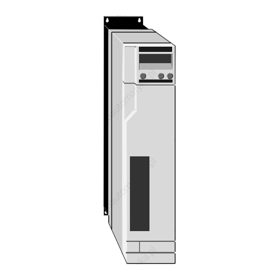
Introduction Case styles Eight DigitAx models cover the range of power ratings. There are two styles and three sizes of case which depend on the power rating of the model. Size 1 and size 2 cases have ingress protection to IP20;... -
Page 10: Method Of Operation
10° ° . The AC supply is rectified and smoothed to apply a Even though all DigitAx constant voltage on a DC bus. This DC bus supplies a Drives are affected in this... -
Page 11: Safety Information
To ensure mechanical safety, additional safety mechanical brake). devices such as electro-mechanical interlocks may be required. The Drive must not be used in a safety- critical application without additional high-integrity protection against hazards arising from a malfunction. DigitAx User Guide Safety information Issue code: dgxu4... - Page 12 This would normally be an appropriate form of independent safety back-up system using simple electro- mechanical components. DigitAx User Guide Safety information Issue code: dgxu4...
-
Page 13: Data
PWM switching frequencies Model sizes 1 and 2 are rated at IP20. The cooling fans for the heatsink are rated at IP20. DBE140 to DBE1100S: 8kHz DBE1500, DBE2200: 4kHz, 8kHz Model size 3 are supplied as a stand-alone unit in a... -
Page 14: Serial Communications
Part 4 (Transient Burst) Level 3 resistance Temperature range –55°C to 155°C –97°F to 240°F –5 Inertia 2.0gm x 10 3.12 Resolver resolution 14-bit when Pr99 < 3200 RPM 12 bit when Pr99 ≥ 3200 RPM DigitAx User Guide Issue code: dgxu4... -
Page 15: Frequency Accuracy
DBE140 DBE220 DBE420 13.6 10.6 DBE600 20.8 13.1 15.2 10.5 DBE750 25.6 15.4 19.7 10.7 13.6 DBE1100S 41.6 23.7 30.5 16.4 21.1 DBE1500 51.2 29.7 39.0 20.6 27.0 DBE2200 76.8 44.9 57.5 31.1 39.8 DigitAx User Guide Issue code: dgxu4... -
Page 16: Dc Bus Choke Ratings
DC bus chokes are fitted internally on the DBE420 to Refer to the following diagrams. DBE1100S drives. No DC bus choke is needed for models DBE140 and DBE220. Ripple frequency = 6 × supply frequency Ratings and values quoted are design minima. - Page 17 Dimension Model size 1 Model size 2 DBE140, DBE220 DBE420, DBE600 DBE750, DBE1100S Height of case Width of case 78.5 Overall depth 323.5 328.5 Depth of heatsink Width of heatsink Height of heatsink Mounting centres 359.4 359.4 top bracket to bottom bracket...
- Page 18 Heated air exhaust Model size 3 DBE1500 DBE2200 Model size 3 Model size 4 Mounting bracket detail Mounting bracket detail Figure 3–2 Dimensions of model size 3 (See table on opposite page) DigitAx User Guide Issue code: dgxu4...
- Page 19 Total height of mounting plates Mounting centres top to bottom Mounting centres Height of aperture for through-panel mounting Width of aperture for through-panel mounting Fixing hole diameter 6mm ( in) clear Figure 3–3 Clearances required around the Drive DigitAx User Guide Issue code: dgxu4...
- Page 20 DigitAx User Guide Issue code: dgxu4...
-
Page 21: Mechanical Installation
Refer to Figure 5–4. over-current trips (OC) in the Drive. For difficult cases, consult the supplier of the Drive. DigitAx User Guide Issue code: dgxu4... -
Page 22: Planning The Installation
If necessary, adjust the size of the enclosure, and re-plan the internal equipment accordingly. Repeat instructions 2 to 4 as many times as required to meet all the requirements. DigitAx User Guide Issue code: dgxu4... - Page 23 Locate as required. Signal cables Plan for all signal cables to Enclosure be routed at least 300mm (12in) distant from any AC power cable. Figure 4–1 Planning the layout of the enclosure DigitAx User Guide Issue code: dgxu4...
-
Page 24: Environment
A ferrite absorber ring and capacitor network may Allow at least 3mm ( in) clearance each side of be used in place of an RFI filter for all models, except the Drive. for models DBE1500 and DBE2200. See Figure 5–4. DigitAx User Guide Issue code: dgxu4... -
Page 25: Ferrite Rings
Mounting hole diameter Figure 4–3 Mounting screw holes and dimensions of cut-out required for remote mounting of the Control Keypad The Control Keypad on model sizes 1 and 2 cannot be located remotely from the Drive. DigitAx User Guide Issue code: dgxu4... -
Page 26: Installing An External Dc
The enclosure is constructed of painted 2mm ( inch) sheet steel Maximum external ambient temperature: 25°C (77°F) Drive PWM switching frequency: 8kHz Value Terminal size 1.50 0.70 Figure 4–4 Dimensions of the bus choke DigitAx User Guide Issue code: dgxu4... -
Page 27: Heat Dissipation In A Ventilated Enclosure
2 1 8 0 5 metres approx If possible, locate heat-generating equipment in the lower part of the enclosure to encourage internal convection. Otherwise, increase the height of the enclosure or install ‘stirrer’ fans. DigitAx User Guide Issue code: dgxu4... - Page 28 DigitAx User Guide Issue code: dgxu4...
-
Page 29: Electrical Installation
Stop function of the Drive does not remove dangerous voltages from the Drive or the driven machine. AC supplies to the Drive must Top panel of DBE140, DBE220 be disconnected using an approved isolation device before any cover is removed or service work is Pin connections performed. - Page 30 –DC DC bus negative Function Type Notes External External braking resistor Choke braking connections Choke –DC bus resistor Ground External +DC bus connection braking Phase U resistor Phase V Output to motor Phase W DigitAx User Guide Issue code: dgxu4...
-
Page 31: Emc Wiring Recommendations
Additional precautions recommendations shown in Figure 5–4 may and guidelines need to be considered. result in vibration in the motor or spurious These are shown in Figures 5–5 and 5–6. trips in the Drive. DigitAx User Guide Issue code: dgxu4... - Page 32 Site ground Alternative safety Do not connect the (if required) ground connection cable shields to the for the motor resolver or motor. Figure 5–5 Models DBE140 to DBE1100S — Recommended AC power and ground connections DigitAx User Guide Issue code: dgxu4...
- Page 33 Armour or shields must be bonded using the connection for the motor isolator case or a flat, wide conductor. Maximum length of conductor: 100mm (4 in) Do not connect the cable shields to the resolver or motor. DigitAx User Guide Issue code: dgxu4...
- Page 34 Radiated emissions in the (if required) the cable shields EMC Data Sheet. to the resolver or Alternative safety motor. ground connections for the motors Figure 5–6 Models DBE1500 to DBE2200 — Recommended AC power and ground connections DigitAx User Guide Issue code: dgxu4...
- Page 35 Alternative motor and braking resistor connections Use these wiring techniques as appropriate for the following: Motor connected to the Drive through a terminal block. Wiring to optional braking resistor external to the enclosure and the resistor shielding. DigitAx User Guide Issue code: dgxu4...
-
Page 36: Ac Supply Cables And Fuses
(1000V ) 3-core pvc-insulated, shielded or armoured cable with copper conductors of the size When a DigitAx is connected to an supply which specified in the table: is subject to severe disturbances, as a result of the Drive to the motor following for example... -
Page 37: Connecting An Internal Or External Braking Resistor
The maximum DC-bus voltage is 800V. Ensure the (external) braking resistor, connecting cables and insulation are suitable for this operating voltage. DigitAx User Guide Issue code: dgxu4... - Page 38 Drive until the cause of a trip has been fully investigated. AC supply isolator Emergency Stop/Start Stop Thermal trip Figure 5–7 Connecting the thermal overload protection relay to the trip circuit of the AC supply isolator DigitAx User Guide 5-10 Issue code: dgxu4...
- Page 39 Thermal connector trip Braking Braking resistor resistor connector connector DBE1500 DBE2200 Thermal trip External braking resistor Upper power terminals Figure 5–8 Connecting internal and external braking resistors to the recommended thermal trip circuit DigitAx User Guide 5-11 Issue code: dgxu4...
-
Page 40: Example Calculations For A Braking Resistor
Then use this figure to calculate the intermittent torque limit for the motor for a 4-second duration. For this example, 3 times the nominal torque rating is assumed, as follows: × × × × 130 3 bINT DigitAx User Guide 5-12 Issue code: dgxu4... - Page 41 Drive to control the DC-bus voltage more accurately. The reduction in value does not increase the power dissipation since the average voltage across the resistor is reduced by the braking transistor operating as a chopper. DigitAx User Guide 5-13 Issue code: dgxu4...
-
Page 42: Control Keypad Connections
Use the tripping curves to find the time that the thermal overload relay will take to trip (eg. 3.5 seconds approximately) Check that the braking resistor can tolerate the overload current for this duration. DigitAx User Guide 5-14 Issue code: dgxu4... -
Page 43: Signal Connections
Sine high Excitation FREQ SIGN Excitation Signal at 7.812 kHz for resolver high FREQ Figure 5–12 DBE140 to DBE1100S Legend printed on the front panel showing the locations of the control signal connectors DigitAx User Guide 5-15 Issue code: dgxu4... - Page 44 When Pr99 ≤3000 RPM output 3V = 1000 RPM When Pr99 > 3000 RPM 3V = 4000 RPM This output must be loaded by 10kΩ in order to produce a load current of 1mA DigitAx User Guide 5-16 Issue code: dgxu4...
- Page 45 Open- +24V Pr20 subtracted from buffer Inhibits reverse every 5ms (anti-clockwise) rotation +24V Open- Pr20 added to buffer every 5 Inhibits forward (clockwise) roatation +24V +24V Pr3No effect Allows rotation in either direction DigitAx User Guide 5-17 Issue code: dgxu4...
- Page 46 Used in conjunction with terminal C7 input to indicate the required direction of rotation of the motor (See parameter b15). Apply 0V for reverse rotation (anti clockwise) Apply +15V (or leave open-circuit) for forward rotation (clockwise) DigitAx User Guide 5-18 Issue code: dgxu4...
- Page 47 Transmit signal, inverted Receive signal, inverted Network termination resistor Direction output DIROUT An external 10kΩ load resistor connected to +10V is required +15V indicates forward direction (clockwise) 0V indicates reverse direction (anti clockwise) DigitAx User Guide 5-19 Issue code: dgxu4...
- Page 48 DigitAx User Guide 5-20 Issue code: dgxu4...
-
Page 49: Control Keypad
Control Keypad Two types of Control Keypad are used in DigitAx Drives. The type used depends on the model size. The Control Keypad can be removed from model size 3. DBE140, DBE220, DBE420, DBE600, DBE750, DBE1100S Figure 6–2 Control Keypad used in models Model sizes 1 and 2 only —... - Page 50 DigitAx User Guide Issue code: dgxu4...
-
Page 51: Parameters
User's table (EEPROM) Data must be manually saved from RAM. Last-used data can be recalled. Last-saved data is automatically sent to RAM when the Drive is powered-on. Figure 7–1 How parameter values are stored and changed DigitAx User Guide Issue code: dgxu4... - Page 52 EEPROM from EEPROM (the Drive must be Enable change disabled before of security code this parameter is adjusted) EEPROM Figure 7–2 Logic diagram showing how parameter values are changed using serial communications DigitAx User Guide Issue code: dgxu4...
-
Page 53: Programming Instructions
Follow the procedure in Displaying a parameter to display the value of parameter b99. Follow the procedure in Changing a parameter value to set the value at 1. The current parameter values are now saved in the User’s Table. DigitAx User Guide Issue code: dgxu4... - Page 54 DigitAx User Guide Issue code: dgxu4...
-
Page 55: Security
Set Pr25 to the User Security Code number. Read/Write parameters can now be edited. Changing a security code Set Pr25 to the existing User Security Code number Follow the procedure in Setting up a security code. DigitAx User Guide Issue code: dgxu4... - Page 56 DigitAx User Guide Issue code: dgxu4...
-
Page 57: Getting Started
Follow the instructions in this chapter to enter values for these parameters in order to get the motor and Drive running. Adjustments can be made later to optimize the system. DigitAx User Guide 10-1 Issue code: dgxu4... -
Page 58: Protection Parameters
* 100 37.5% Since a whole number must be entered in Pr45, the value entered in this example would be 37 or 38. Figure 10–2 Models DBE140, DBE220, DBE420, DBE600, DBE750 — Relationship between maximum current (Pr42) and nominal current (Pr45) -
Page 59: Pid Parameters
200 or . The full-scale speed calibration pot allows the full scale speed to be adjusted to produce the correct speed for a specified speed reference input signal. Figure 10–4 Example operating cycle DigitAx User Guide 10-3 Issue code: dgxu4... -
Page 60: Resolver Phasing
If the value of b33 = 0, at least one alarm direction, when viewed from the shaft end of condition exists. Investigate as necessary. If the value of b89 = 1, the Drive has entered DigitAx User Guide 10-4 Issue code: dgxu4... -
Page 61: Calibration
Pr1, Pr2, Pr3. Increase the inversion frequency by decreasing the value of Pr19. Set Pr19 at 2.5 (0.2Hz) Note This setting depends on the transmission ratio and the mechanical limitations of the system. DigitAx User Guide 10-5 Issue code: dgxu4... -
Page 62: Methods Of Speed Control
Scaling is as follows: 200 to 3000 3000 When Pr99 ≤3000, >3000 6000 8192 pulses = 1 revolution, i.e. 409.6kHz gives 3000 When Pr99 >3000, 4096 pulses = 1 revolution, i.e. 409.6kHz gives 6000 DigitAx User Guide 10-6 Issue code: dgxu4... -
Page 63: 10.10 Methods Of Torque Control
±100% of I Set b2 at 0 to disable the Drive (See Pr42). Ensure the motor is stopped. Set b6 at 1 to select torque control. Set b8 at 0 to select analog torque reference DigitAx User Guide 10-7 Issue code: dgxu4... -
Page 64: 10.11 Methods Of Position Control
The value that will actually be written into the controller. The acceleration and deceleration ramps buffer is given by: Position reference = (Pr76 x 1000) + Pr75 DigitAx User Guide 10-8 Issue code: dgxu4... - Page 65 (and hence whether ramps are selected to act on the speed losing the position reference), the limit-switch reference. function should be used by setting b16 at 1. This DigitAx User Guide 10-9 Issue code: dgxu4...
-
Page 66: 10.12 Quick Reference
Reference Pulse Limit- Terminal switch Digital Fixed increment Forward Reverse 0 = logic 0 = 0V = Stop (X = don’t care) Stop, hold and orientate See Spindle orientation earlier in this chapter. DigitAx User Guide 10-10 Issue code: dgxu4... -
Page 67: 10.13 Programmable Outputs
Motor status (running/stopped) Post-ramp speed reference. Scaling: ±5V = ±6000 RPM At-speed status Speed loop saturation status The output from terminal B17 is the analog Drive enabled status tacho signal. Braking resistor overload DigitAx User Guide 10-11 Issue code: dgxu4... - Page 68 Pr21 Limit Switch Buffer inc./dec. Pr20 Digital Select Auto Digital select select Buffer Pr19 time Inc./Dec. Pr18 1 = Limit switch active Figure 10–6 Logic diagram showing speed reference selection and position control DigitAx User Guide 10-12 Issue code: dgxu4...
- Page 69 Bandwidth Speed Ramps Pr13 Proportional Loop Ramp to Derivative Pr09 Pr14 Stop Hard Pr10 Pr15 Integral Stop Pr11 Pr12 Pr27 Pr37 Pr53 Pr54 Shaft Positioning Speed Feedback DigitAx User Guide 10-13 Issue code: dgxu4...
- Page 70 Voltage Voltage Temperature Pre-Alarm Incorrectly (400V) (840V) Parameters b06, b49 and Pr95 can be changed only when the Drive is disabled Figure 10–7 Logic diagram showing the torque loop, trip logic and I/O DigitAx User Guide 10-14 Issue code: dgxu4...
- Page 71 Pr30 I 2 t alarm Pr31 Over temp. pre-alarm Drive OK +24V Over-current trip Motor direction Zero speed At speed Speed loop saturation B7 (Pr30) Drive enabled B8 (Pr31) Internal braking resistor overload DigitAx User Guide 10-15 Issue code: dgxu4...
- Page 72 = 0 Limitation by external analog reference Pr42 = 100 b11 = 0 b11 = 1 Set Pr42 at the Pr42 = 100 required value Figure 10–8 Select speed control or current control DigitAx User Guide 10-16 Issue code: dgxu4...
- Page 73 Pr21 = 2 b17 = 1 b23 = 1 b23 = 0 Set speeds Set ramps Pr0, Pr1, Pr2, Pr3 Pr9, Pr10, Pr11, Pr12 Figure 10–9 Select pulse offset control switching, or limit-switch function DigitAx User Guide 10-17 Issue code: dgxu4...
- Page 74 Set Pr9, Pr10, Pr11, Pr12 Used in speed control mode only. Activated when b18 is set at 1 or +24V applied to pin B6 (b18 set at 0) Figure 10–10 Select Stop-and-hold or Stop-orientate and hold DigitAx User Guide 10-18 Issue code: dgxu4...
-
Page 75: List Of Parameters
Voltage level of DC bus 0 to 1024 Res. Slope in milliseconds per 1000 RPM. val. R–W Pr10 Acceleration ramp — reverse 1 to 3000 Res. val. Slope in milliseconds per 1000 RPM. DigitAx User Guide 11-1 Issue code: dgxu4... - Page 76 The indications are as follows: Available values are as follows: Terminal Pr18 300, 600 1200, 2400, 4800, 9600, 19200 The host computer must be set at the same Baud rate as the Drive. DigitAx User Guide 11-2 Issue code: dgxu4...
- Page 77 Analog limit (rectified) (Pr39) when b11 = 1 b41 Motor stopped Digital limit Pr42 b42 At Speed 0 is shown when the Drive is disabled. b48 Speed loop saturation b4 Drive enable status b95 Braking resistor overload DigitAx User Guide 11-3 Issue code: dgxu4...
- Page 78 0 to 3 Res. Range: val. DBE140 to DBE750: 20% to 50% When Pr68 = 0, pulses per revolution = 256 DBE1100S to DBE2200: 20% to 67% When Pr68 = 1, pulses per revolution = 512 When Pr68 = 2, pulses per revolution = 1024...
-
Page 79: Bit Parameters
Refer to terminal B14. when the Drive is reset by setting b03 at 1. When Pr98 is interrogated using Serial Communications, a number representing the trip is transmitted. The numbers are as follows: DigitAx User Guide 11-5 Issue code: dgxu4... - Page 80 When b12 is set at 0, refer to b13. When b12 is set at 1, the output signal represents When b7 = 0, ramps are disabled. the motor current (16V pk-pk ≡ I peak When b7 = 1, ramps are enabled. DigitAx User Guide 11-6 Issue code: dgxu4...
- Page 81 When b33 is set at 0, at least one alarm is active. When b33 is set at 1, no alarm is active. The status of this parameter is produced as a logic signal on terminal B15. DigitAx User Guide 11-7 Issue code: dgxu4...
- Page 82 When b53 is set at 1, stop, orientate, and hold is selected. See Pr27. External Trip Alarm Res. val. b55 = 0 indicates no external trip. b55 = 1 indicates external trip active. DigitAx User Guide 11-8 Issue code: dgxu4...
- Page 83 = 0 indicates heat-sink temperature below permitted maximum. b85 = 1 indicates heat-sink temperature above permitted maximum. Resolver break trip Res. val. b86 = 0 indicates no fault. b86 = 1 indicates a fault present. DigitAx User Guide 11-9 Issue code: dgxu4...
- Page 84 SAVE while parameters are being saved. b99 is related to b1 and b5. When b99 is set at 0, no saving occurs. When b99 is set at 1, parameters are saved. DigitAx User Guide 11-10 Issue code: dgxu4...
-
Page 85: Summary Of Default Values
Pr71 Position loop integral gain Pr75 Pr75 Position reference (via serial comms only) Position reference (via serial comms only Pr76 Pr76 Pr95 Pr95 Number of motor poles Pr99 Pr99 3000 Speed – full-scale DigitAx User Guide 11-11 Issue code: dgxu4... - Page 86 Serial link (interface) mode Stop and hold Digital stop mode selector Disable External trip (Et) enable +24V = STOP Invert logic of STOP signal Relative At-speed relative or absolute Save Working Table to EEPROM DigitAx User Guide 11-12 Issue code: dgxu4...
-
Page 87: Trip Codes And Fault Finding
Hardware Fault Trip or Drive Operating Incorrectly There is an internal hardware fault. Remove then re-connect AC power to the Drive. This may clear the fault, otherwise consult the supplier of the Drive. DigitAx User Guide 12-1 Issue code: dgxu4... -
Page 88: Fault Finding
Control software Keypad. Model size 34 Model size 34 If dEf dEf re-appears when AC power is next applied, change the NOVRAM on the control board. DigitAx User Guide 12-2 Issue code: dgxu4... -
Page 89: Serial Communications
The Baud rate is selected using parameter Pr23. The selected rate must be the same as that of the host computer. Figure 13–1 Up to 32 Drives can be connected to each communications port of the host computer DigitAx User Guide 13-1 Issue code: dgxu4... -
Page 90: Message Structure
Serial address code To address an individual parameter, the host must send a code that relates to that parameter. There Parameter identifier are two types of parameter in the DigitAx: Data field Block checksum (BCC) Numerical parameters Pr00 to Pr99... -
Page 91: Messages From Host To Drive
Message received, but not carried out. The data is out of range, or the message was corrupted during transmission. The EOT character and Drive address can be omitted from subsequent write instructions to that Drive. DigitAx User Guide 13-3 Issue code: dgxu4... -
Page 92: Terminal Mode
= sign, as follows: Mode. Data field Read-Only Parameter P 6 = – 0 3 5 . 8 An attempt has been made to write to a Ctrl-M read-only (OR) parameter. DigitAx User Guide 13-4 Issue code: dgxu4... -
Page 93: Parameters Related To Serial Communications
Serial communications mode ANSI mode ANSI When b52 b52 is set at 0, standard is selected When b52 b52 is set at 1, Terminal mode is selected DigitAx User Guide 13-5 Issue code: dgxu4... - Page 94 DigitAx User Guide 13-6 Issue code: dgxu4...
-
Page 95: Setting The Pid Gains
Waveform showing ideal response Excessive derivative gain can have the following effects: Excessive heating of the motor due to extra current Motor shaft oscillation I2t current limiting Reduced speed of response as shown in Figure A–4 DigitAx User Guide Issue code: dgxu4... -
Page 96: Evaluating The Pid Gains
For systems requiring a stiff response, the angle would be around 6 ° . For a softer response, the angle may be up to 60 ° DigitAx User Guide Issue code: dgxu4...
Need help?
Do you have a question about the DBE140 and is the answer not in the manual?
Questions and answers