Table of Contents
Advertisement
Quick Links
Cisco Firepower 8000 Series Getting
Started Guide
For the 81xx, 82xx, and 83xx Firepower and AMP models
Updated: February 15, 2016
This guide is organized as follows:
Package Contents
Deploying the Appliance
Cabling the Device
Installing the Firepower 8000 Series Device
Initial Device Setup
Restoring a Device to Factory Defaults
Scrubbing the Hard Drive
Related Documentation
Package Contents
This section lists the items included with each model. Note that contents are subject to change, and your exact contents
might contain additional or fewer items.
Chassis Models
A Firepower 8000 Series device can be delivered on a variety of chassis:
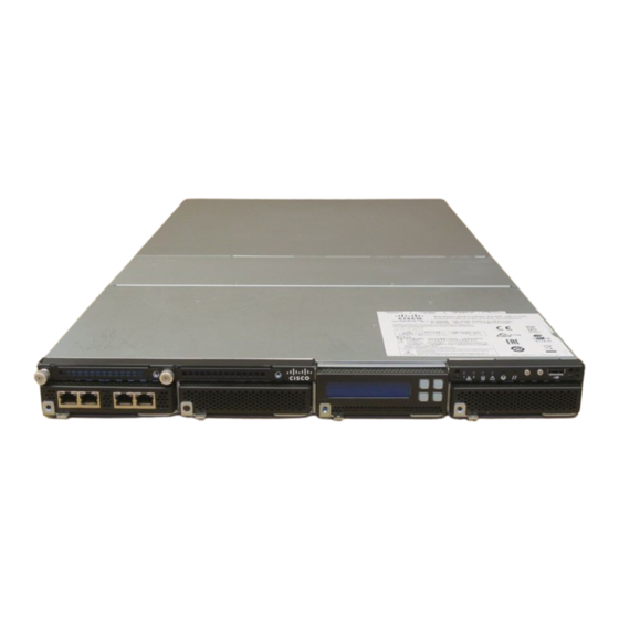
The Firepower 8120/8130/8140 and the AMP8050/AMP8150 are available as 1U appliances and can contain
up to three sensing modules. The following illustration of the rear of the chassis indicates the location of the
management interface.
Figure 1
Firepower
1
Management interface
Firepower 8130 (1U model), this chassis and can contain up to three sensing modules.
Firepower 8000 Series Getting Started Guide
81xx and AMP 8xxx Series Chassis and Management Interface
1
Cisco Systems, Inc.
www.cisco.com
1
Advertisement
Table of Contents

Subscribe to Our Youtube Channel
Related Manuals for Cisco Firepower 8120


Summary of Contents for Cisco Firepower 8120
-
Page 1: Package Contents
A Firepower 8000 Series device can be delivered on a variety of chassis: The Firepower 8120/8130/8140 and the AMP8050/AMP8150 are available as 1U appliances and can contain up to three sensing modules. The following illustration of the rear of the chassis indicates the location of the management interface. - Page 2 Package Contents Note: Firepower 8120/8130/8140 and the AMP8050/AMP8150 models have identical chassis. If you are not sure which model you have, see your packing list. Note: You can add a stacking kit to the Firepower 8140 for a total 2U configuration.
-
Page 3: Included Items
Package Contents — Firepower 8360 and AMP8360 (4U stacked models), the 40G primary chassis contains one stacking module and up to six sensing modules. One secondary chassis contains one stacking module. You can add up to two stacking kits for a total 8U configuration. —... -
Page 4: Stacking Module
Package Contents Dual-Port 10GBASE Fiber Configurable Bypass NetMod Cable: Local Connector (LC) optical transceivers, either MMSR or SMLR Passive configurations: 1 or 2 Inline configurations: 1 Dual-Port 40GBASE-SR4 Fiber Configurable Bypass NetMod For use only with Firepower 8270/8290, 8370/8390, AMP8370/8390 or 40G-capable Firepower 8250/8260, 8350/8360, or AMP8350/8360 ... -
Page 5: Device Stacks
AMP8350 appliances Device Stacks You can stack devices in the following configurations: Two Firepower 8140s (not available for Firepower 8120/8130, AMP8050/AMP8150) Up to four Firepower 8250s, up to four Firepower 8350s, or up to four AMP8350s ... -
Page 6: Cabling Diagrams
Package Contents To use the 8000 Series stacking cable: To insert the cable, hold the cable end with release tab facing up, then insert the keyed end into the port on the stacking module until you hear the latch click into place. ... -
Page 7: Deploying The Appliance
Deploying the Appliance Deploying the Appliance Your device is typically deployed inside a firewall, where it is connected to your trusted management network and the various network segments you want to monitor. In a simple deployment scenario, you connect the management interface on your device to your trusted management network using an Ethernet cable, then connect the sensing interfaces to the... -
Page 8: Connecting The Sensing Interfaces
Cabling the Device Use the appropriate cables (as indicated by your interface) and cabling diagram for the interface you want to configure, then use the web interface on the Firepower Management Center to configure the interfaces. See Connecting the Sensing Interfaces, page Connecting the Sensing Interfaces This section describes the physical connection of the sensing interfaces. -
Page 9: Installing The Firepower 8000 Series Device
You can connect a computer to any 8000 Series appliance using the physical serial port. Connect the appropriate rollover serial cable (also known as a NULL modem cable or Cisco console cable) at any time, then configure the remote management console to redirect the default VGA output to the serial port. To interact with the appliance, use terminal emulation software such as HyperTerminal or XModem. - Page 10 Installing the Firepower 8000 Series Device default gateway: 192.168.45.1 Using an Ethernet cable, connect the network interface on the local computer to the management interface on the appliance. Note that the management interface is preconfigured with a default IPv4 address. However, you can reconfigure the management interface with an IPv6 address as part of the setup process.
-
Page 11: Initial Device Setup
Initial Device Setup Initial Device Setup After you deploy and install a new Firepower device, you must complete a setup process. The setup process also allows you to perform many initial administrative-level tasks, such as setting the time, registering and licensing devices, and scheduling updates. -
Page 12: Initial Setup Using The Web Interface
Initial Device Setup Regardless of how you are connected to the device, you can use the CLI to set it up; see Initial Setup Using the CLI, page If you are setting up a reimaged device and you kept your network settings as part of the restore process, you can access the CLI via SSH or a Lights-Out Management (LOM) connection. - Page 13 Firepower Device” in the Firepower 8000 Series Hardware Installation Guide. Remote Management You must manage a Cisco device with a Firepower Management Center. In this two-step process, you first configure remote management on the device, then add the device to a Firepower Management Center. For your convenience, the setup page allows you to preregister the device to the Firepower Management Center that will manage it.
- Page 14 Initial Device Setup Detection Mode The detection mode you choose for a device determines how the system initially configures the device’s interfaces, and whether those interfaces belong to an inline set or security zone. The detection mode is not a setting you can change later; it is simply an option you choose during setup that helps the system tailor the device’s initial configurations.
-
Page 15: Initial Setup Using The Cli
Configuration CLI access. Changing any user’s password for the web interface also changes the password for the CLI, and vice versa. Cisco recommends that you use strong password that is at least eight alphanumeric characters of mixed case and includes at least one numeric character. Avoid using words that appear in a dictionary. For more... -
Page 16: Register A Firepower Device To A Management Center Using The Cli
Register a Firepower Device to a Management Center Using the CLI If you configured a Firepower device using the CLI, Cisco recommends that you use the CLI to register the device to a Firepower Management Center at the conclusion of the setup script. It is easiest to register a device to its Firepower Management Center during the initial setup process, because you are already logged into the device’s... -
Page 17: Next Steps
The device is ready to be added to a Firepower Management Center. Next Steps After you complete the initial setup process for an appliance and verify its success, Cisco recommends that you complete various administrative tasks that make your deployment easier to manage. You should also complete any tasks you skipped during the initial setup, such as device registration and licensing. -
Page 18: Redirecting Console Output
By default, Firepower devices direct initialization status, or init, messages to the VGA port. If you want to use the physical serial port or SOL to access the console, Cisco recommends you redirect console output to the serial port after you complete the initial setup. -
Page 19: Restoring A Device To Factory Defaults
Configuration and Event Backup Guidelines Before you begin the restore process, Cisco recommends that you delete or move any backup files that reside on your appliance, then back up current event and configuration data to an external location. -
Page 20: Obtaining The Restore Iso And Update Files
Serial Connection/Laptop You can use a rollover serial cable (also known as a NULL modem cable or a Cisco console cable) to connect a computer to the appliance. See the hardware specifications for your appliance to locate the serial port. To interact with the appliance, use terminal emulation software such as HyperTerminal or XModem. -
Page 21: Beginning The Restore Process
(sometimes called expert mode). Starting the Restore Utility Using KVM or Physical Serial Port For Firepower devices, Cisco provides a restore utility on an internal flash drive. Note: Do not use a KVM console with USB mass storage to access the appliance for the initial setup because the appliance may attempt to use the mass storage device as a boot device. -
Page 22: Starting The Restore Utility Using Lights-Out Management
Restoring a Device to Factory Defaults To start the restore utility: Using your keyboard/monitor or serial connection, log into the appliance using an account with Administrator privileges. The password is the same as the password for the appliance’s web interface. Reboot the appliance. -
Page 23: Using The Interactive Menu To Restore An Appliance
Restoring a Device to Factory Defaults To start the restore utility using Lights-Out Management: At your computer’s command prompt, enter the IPMI command to start the SOL session: For IPMItool, type: sudo ipmitool -I lanplus -H IP_address -U username sol activate For ipmiutil, type: sudo ipmiutil sol -a -V4 -J3 -N IP_address -U username -P password Where... - Page 24 Downloading the ISO and Update Files and Mounting the Image, page However, Cisco recommends you double-check the settings in the restore configuration before proceeding. Note: To use a previously saved configuration, start with menu option...
-
Page 25: Identifying The Appliance's Management Interface
Restoring a Device to Factory Defaults (optional) — Updating System Software and Intrusion Rules During Restore, 3 Select Patches/Rule Updates page — see Downloading the ISO and Update Files and Mounting the Image, page 4 Download and Mount ISO 5 Run the Install —... -
Page 26: Updating System Software And Intrusion Rules During Restore
Use the series of pages presented by the restore utility to provide the necessary information for the protocol you chose, as described in Table If your information was correct, the appliance connects to the server and displays a list of the Cisco ISO images in the location you specified. Select the ISO image you want to use. -
Page 27: Downloading The Iso And Update Files And Mounting The Image
Restoring a Device to Factory Defaults To install updates as part of the restore process: From the main menu, select 3 Select Patches/Rule Updates The restore utility uses the protocol and location you specified in the previous procedure (see Specifying ISO Image Location and Transport Method, page 25) to retrieve and display a list of any system software update files in that location. - Page 28 Restoring a Device to Factory Defaults Note: If you are restoring an appliance to the same major version, or if this is your second pass through the process, skip to the next procedure: Second or Only Pass, page To perform the first pass of a two-pass restore process: From the main menu, select 5 Run the Install When prompted (twice), confirm that you want to reboot the appliance.
-
Page 29: Saving And Loading Restore Configurations
Restoring a Device to Factory Defaults In most cases, you do not want to delete these settings, because it can make the initial setup process shorter. Changing settings after the restore and subsequent initial setup is often less time consuming than trying to reset them now. -
Page 30: Setting Up Lights-Out Management
Restoring a Device to Factory Defaults To load a saved restore configuration: From the main menu, select 7 Load Configuration The utility presents a list of saved restore configurations. The first option, , is the configuration you default_config last used to restore the appliance. The other options are restore configurations that you have saved. Select the configuration you want to use. - Page 31 IP address assigned to it by the DHCP server. Because of this, Cisco recommends you configure the Firepower 7050 BMC with a static IP address. Alternately, you can disconnect the network cable and reconnect it, or remove and restore power to the device to force renegotiation of the link.
-
Page 32: Enabling Lom And Lom Users
Restoring a Device to Factory Defaults Enabling LOM and LOM Users Before you can use LOM to restore an appliance, you must enable and configure the feature. You must also explicitly grant LOM permissions to users who will use the feature. You configure LOM and LOM users on a per-appliance basis using each appliance’s local web interface. -
Page 33: Scrubbing The Hard Drive
Scrubbing the Hard Drive Scrubbing the Hard Drive You can securely scrub the hard drive on Management Centers and Firepower devices to ensure that its contents can no longer be accessed. For example, if you need to return a defective appliance that contains sensitive data, you can use this feature to overwrite the data. - Page 34 Related Documentation Firepower 8000 Series Getting Started Guide...
Need help?
Do you have a question about the Firepower 8120 and is the answer not in the manual?
Questions and answers