Table of Contents
Advertisement
Advertisement
Table of Contents

Related Manuals for Xtralis VESDA ECO


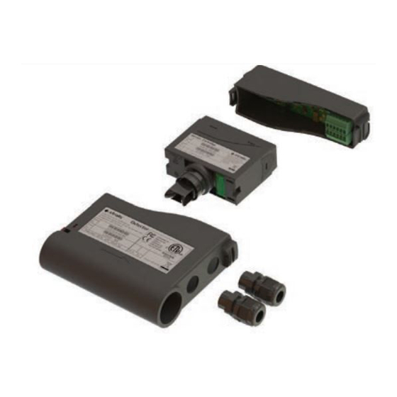
Summary of Contents for Xtralis VESDA ECO
- Page 1 Product Guide May 2010 Document Number 17898_05 Part Number LF41308...
- Page 3 Xtralis is not responsible and cannot be held accountable for any liability that may arise due to improper use of the equipment and/or failure to take proper precautions. Only persons trained through an Xtralis accredited training course can install, test and maintain the system.
- Page 4 Xtralis or its representatives. Total Liability To the fullest extent permitted by law that any limitation or exclusion cannot apply, the total liability of Xtralis in relation to the products is limited to: (i) in the case of services, the cost of having the services supplied again; or (ii) in the case of goods, the lowest cost of replacing the goods, acquiring equivalent goods or having the goods repaired.
- Page 5 VESDA ECO Detector by Xtralis Product Guide Document Conventions The following typographic conventions are used in this document. Convention Description Used to denote: emphasis Bold Used for names of menus, menu options, toolbar buttons Used for names of menus, menu options, toolbar buttons...
- Page 6 Product Guide VESDA ECO Detector by Xtralis Codes and Standards Information for Air Sampling Gas Detection We strongly recommend that this document is read in conjunction with the appropriate local codes and standards for gas detection and electrical safety. This document contains generic product information and some sections may not comply with all local codes and standards.
- Page 7 VESDA ECO Detector by Xtralis Product Guide Terms and Abbreviations The following is a list of common terms and conditions relating the product and gas detection in general that may be used in connection with this document. Aspirating Smoke Detector...
- Page 8 Product Guide VESDA ECO Detector by Xtralis Time The response time of the gas sensor to a step change in the input gas level to “XX”% of the final reading, e.g. T is the time taken for the measurement to reach 90% of a step change in the gas input level.
-
Page 9: Table Of Contents
VESDA ECO Detector by Xtralis Product Guide Contents Overview ........................1 Introduction to the VESDA ECO ..............1 Packing Contents ..................1 Product Overview ..................2 Operation ....................... 3 Key Features ....................4 Detector Location ....................5 Installation ....................... 7 Air Inlet/Outlet Pipe Connections .............. - Page 10 Product Guide VESDA ECO Detector by Xtralis Using Xtralis VSC with ECO ................ 39 Opening a connection ..............39 User Access Limitations ................41 ECO Configuration ..................43 General Tab .................. 44 Air Flow Tab .................. 45 Latching Tab ................. 46 Relays Tab ..................
-
Page 11: Overview
25mm or ¾” BSP air sampling pipe network. The VESDA ECO can detect a range of flammable, toxic and oxygen gas hazards The VESDA ECO can detect a range of flammable, toxic and oxygen gas hazards... -
Page 12: Product Overview
Xtralis trained and accredited distributors / be fitted and commissioned by Xtralis trained and accredited distributors / installers only. The VESDA ECO gas detector has been designed and approved for use with proved for use with compatible Xtralis manufactured aspirating systems only. The VESDA ECO only. -
Page 13: Operation
VESDA ECO Detector by Xtralis Product Guide Operation The ECO is designed to be inserted into an aspirated air sampling pipe network to The ECO is designed to be inserted into an aspirated air sampling pipe network to detect and indicate the concentration of background gas levels. -
Page 14: Key Features
Xtralis VSM4 monitoring package or other system. Event logs are stored via the removable microSD card and retrieved to a host PC running the Xtralis VSC software either directly using an SD Card connection or via the USB interface. -
Page 15: Detector Location
The initial stage of the design process requires completion and submission of the The initial stage of the design process requires completion and submission of the VESDA ECO application form. This is available from, and should be returned s is available from, and should be returned to, your local Xtralis Field Applications Engineer or qualified distributor / installer. - Page 16 In existing systems it may be necessary to run additional pipe work for the benefit of gas detection. For further information on designing air sampling pipe networks please refer to the Pipe Network Design and Installation Manuals or contact your local Xtralis Field Applications Engineer (FAE). Detector Location...
-
Page 17: Installation
VESDA ECO Detector by Xtralis Product Guide Installation Any installation of an ECO gas detector must comply with loca Any installation of an ECO gas detector must comply with local electrical safety regulations and to the fire safety regulations when being fitted as when being fitted as part of a fire detection network. - Page 18 Product Guide VESDA ECO Detector by Xtralis Figure 3. ECO Mechanical Dimensions Installation 17898_05...
-
Page 19: Mechanical Installation
VESDA ECO Detector by Xtralis Product Guide Mechanical Installation Do not install your ECO detector if there are any signs of shipping Do not install your ECO detector if there are any signs of shipping damage. Inform your distributor if there is any visible damage. - Page 20 Product Guide VESDA ECO Detector by Xtralis • Ensure that there is sufficient access to the Enclosure lid such that it can be removed and the sensor cartridge accessed (refer to the Maintenance and Service section on page 76). Installation...
-
Page 21: Electrical Installation
VESDA ECO Detector by Xtralis Product Guide Electrical Installation Any installation of an ECO gas detector must comply with local electrical Any installation of an ECO gas detector must comply with local electrical safety regulations. If any of the following instructions conflict with the safety regulations. - Page 22 Product Guide VESDA ECO Detector by Xtralis Upon removing the lid, the two 8 way connection terminals are exposed. The pin numbering of these connections is indicated in Figure 5 below. Figure 5. Detector Internal Connector Terminal Allocations The electrical functions of the terminals are as follows...
-
Page 23: Cable Specification
VESDA ECO Detector by Xtralis Product Guide Cable Specification The 8 way screw terminals located on the main PCB will accept wire sizes up to 1.0 (17AWG). It is not practical to use cable of this size if more than half of the terminals are to be used, due to the internal restrictions of space and the size of the cable entries. -
Page 24: Power Supply Connection
Product Guide VESDA ECO Detector by Xtralis VESDA ECO Detector by Xtralis Power Supply Connection When connecting the power supply to the ECO device the system designer and stem designer and installer must take consideration of the voltage drops over long lengths of cable. -
Page 25: Rs485 Interface Connection
1/8 loads, in which case up to 256 units can be include on the bus. This is reduced to a practical limit of 247 units by the specification of the Modbus interface. When using either the Xtralis VSC or VSM4 tools, the number of units on a single bus is limited to 32. - Page 26 Product Guide VESDA ECO Detector by Xtralis By default, the Modbus protocol settings for an RS485 interface are • Baudrate 19200 • Parity Even • Stop Bits 1 These are the default settings programmed into the ECO at shipping. Refer to the ECO Configuration section on page 33 for details of how to program the address, Baudrate etc.
- Page 27 VESDA ECO Detector by Xtralis Product Guide When a junction/terminal box (also known as a passive tap) is used to connect an RS485 device, such as an ECO, to the bus then the branch must not be longer than Using a “repeater” or “signal amplifier” or “active tap”, the cable lengths can be extended, but each length between repeaters is limited to the 1200m length restriction and must be terminated correctly.
-
Page 28: Relay Connections
Product Guide VESDA ECO Detector by Xtralis Relay Connections The relay connections on SKT1 can be made using a standard multi-core unscreened cable. There are four relays provided, numbered 1 to 4 along SKT1 as indicated in Figure 9. Installation... - Page 29 VESDA ECO Detector by Xtralis Product Guide Figure 9 Relay Terminal Connections The terminals of Relays 1 to 3 are physically connected to the Normally Closed contacts of the relays. The Relay 4 terminals are connected to the Normally Open contacts of the relay.
- Page 30 Connection to Fans and Beacons Xtralis assumes no liability for any damage or injury Xtralis assumes no liability for any damage or injury caused as a result of using the ECO product to control voltages above those f result of using the ECO product to control voltages above those for which it is rated.
-
Page 31: 4-20Ma Current Sources
VESDA ECO Detector by Xtralis Product Guide 4-20mA Current Sources The two current source outputs (A and B) on the ECO are designed to be wired to industry standard 4-20mA current monitoring devices. If the current loop monitoring device uses a voltage input topology then each of the current output lines must be terminated as closely to the monitoring device as possible with a load resistor connected to the 0V reference of the power supply to the system. - Page 32 Product Guide VESDA ECO Detector by Xtralis So for example, in an installation with a supply voltage of 19V, a cable length of 250m and a cable resistance of 0.05 m (Ohms per metre), gives us a maximum load resistance R of ..
-
Page 33: Digital Input Connection
VESDA ECO Detector by Xtralis Product Guide Digital Input Connection The digital Input pin can be used to reset the active alarm conditions. Connecting the input pin terminal to the Power supply return terminal for 5 seconds will clear the alarms. -
Page 34: Principles Of Operation
To perform configuration operations on the ECO Detector you will need to have the Xtralis VSC software tool installed on your computer. The software is available from the Xtralis website along with installation instructions, which can also be found in Appendix B. -
Page 35: Status Indicator Operation
Product Guide Status Indicator Operation The VESDA ECO has four LEDs to indicate power, fault and alarms. These LEDs The VESDA ECO has four LEDs to indicate power, fault and alarms. These LEDs can be inactive; flashing or on steady, depending on its assigned function and the can be inactive;... -
Page 36: Modbus Interface
Modbus Interface The implementation of the Modbus interface for the ECO detector is integrated into Xtralis VSC and Xtralis VSM4. Where a 3rd party control application is to be used instead, the installer should refer to the ECO Modbus Interface specification, document number 17887, available from your distributor or local Xtralis sales representative. -
Page 37: Relay Contacts
VESDA ECO Detector by Xtralis Product Guide Relay Contacts The ECO unit uses Volt Free Relay contacts to indicate its local alarm status. In default setting these relay outputs are switched in conjunction with the Activation of the LEDs on the ECO Top surface (See Status Indicator Operation) -
Page 38: Event Logging
Logging of events to the microSD Card is integral to the operation of the unit, this allows the retrieval of historical data from the unit either using the Communications bus and Xtralis VSC or where accessible the internal data storage card can be removed and the data read using a PC. -
Page 39: Current Outputs
VESDA ECO Detector by Xtralis Product Guide Current Outputs The ECO unit has two local analogue outputs, labeled as A & B, which are used in a 4-20 mA source configuration. Current output A is mapped to indicated the level of the Sensor 1 Gas reading. The 4mA level is mapped to a gas reading of 0, the 20mA level is mapped to the maximum sensor measurement (e.g. -
Page 40: Alarms
Product Guide VESDA ECO Detector by Xtralis Alarms The ECO detector will generate Alarm conditions when the associated gas reading exceeds the configured threshold(s). These alarm conditions are used to switch the state of both the Relays AND the status indicators (see page 25). -
Page 41: Calibration
Supplies of the necessary calibration and test gas can be obtained from a number gas can be obtained from a number of sources. Xtralis does not supply calibration gas directly, but your local Xtralis supply calibration gas directly, but your local Xtralis sales contact or distributor will be able to provide you with a list of local suppliers. - Page 42 • When bump testing, if necessary disable the Alarm relays to avoid initiation on associated executive actions, for Xtralis VSC refer to page 54. Ensure that the measured value is within the expected range for the gas concentration applied, and that any related indicators, relays and current outputs react as expected.
-
Page 43: Configuration
However, should it be necessary to modify the configuration for a specific user application this can be achieved by using Xtralis VSC. To install the Xtralis VSC application, refer to Appendix B – Software Installation on page 86. VSC Connection Configuration The first time Xtralis VSC is run, the communications ports must be configured. - Page 44 Product Guide VESDA ECO Detector by Xtralis Figure 16 Add Connection, Select Connection Type Select the ‘ECO’ option and then click the ‘Next’ button. The wizard now prompts the user to select the type of serial communications to use when communicating with ECO.
- Page 45 VESDA ECO Detector by Xtralis Product Guide Figure 17 Add Connection Dialog Click the on the button for the required option and click the ‘Next’ button. The Wizard will update and prompt the user to select the Serial Comms port to use when communicating with ECO as shown in Figure 18.
- Page 46 Product Guide VESDA ECO Detector by Xtralis Figure 18 Select Comm. Port Select the serial communications port you wish to use from the ‘COM Port’ drop down list. In order to determine the COM port number allocated to a USB connected ECO please refer to Appendix B –...
- Page 47 To make a connection the default, highlight the required connection and then click the ‘Set as Default’ button. (Recommended) To make Xtralis VSC automatically use the default connection whenever the user opens a connection, check the ‘Automatically connect to default’ check box.
- Page 48 Product Guide VESDA ECO Detector by Xtralis The ‘Connection Manager’ dialog box should now look similar to Figure 20. Figure 20 Connection Manager Click the ‘Close’ button to return to Xtralis VSC’s main window. Configuration 17898_05...
-
Page 49: Using Xtralis Vsc With Eco
The following sections of the manual only concentrate on configuration and operational aspects of the ECO detectors. For more information on general use of Xtralis VSC please refer to the Xtralis VSC online help. Opening a connection To open a connection with ECO detectors click the ‘Open Connection and View’... - Page 50 ‘Device View’. It will look similar to that shown in Figure 23. Figure 23 VSC Main Window An Xtralis VSC window comprises a number of distinct zones as shown in Figure 23. See Table 3 for their definitions.
-
Page 51: User Access Limitations
To change some of the configuration settings of an ECO unit it will be necessary to have access at an appropriate level. When the user attempts to access a variable or function that requires approved access, Xtralis VSC will display the logon dialog shown in figure 25. - Page 52 Product Guide VESDA ECO Detector by Xtralis Figure 25 Selecting the Access Level To complete the login process, select the required access level from the drop down list (the list will contain all those levels which have access to the required function) and enter the PIN in the field provided.
-
Page 53: Eco Configuration
ECO Configuration To configure an ECO detector, double click the ECO detector that is to be set-up in the ‘Detector overview’ zone of Xtralis VSC main window as shown in Figure 26 Xtralis VSC Sensor Display Figure 26 Xtralis VSC Sensor Display The ‘ECO Detector’... -
Page 54: General Tab
The ‘Location’ field should be edited to clearly identify where in the system pipe network the ECO detector is placed, and is limited to 32 characters. The contents of this field will appear next to the ECO device in the Xtralis VSC overview field, see below When using the Modbus interface, the ‘Modbus Address’... -
Page 55: Air Flow Tab
VESDA ECO Detector by Xtralis Product Guide of the Address is “1”. For more information on Modbus addresses please refer to the Modbus Interface Air Flow Tab The ‘Air Flow’ tab, shown in Figure 28, is used to specify the thresholds for the Air Flow fault conditions. -
Page 56: Latching Tab
Product Guide VESDA ECO Detector by Xtralis Latching Tab The ‘Latching’ tab, seen in Figure 29 ECO Detector, Latching Tab allows the latching behavior of Alarms and Fault conditions to be configured. Note : This affects the operation of both the Relays and the status indicators. -
Page 57: Relays Tab
VESDA ECO Detector by Xtralis Product Guide Relays Tab The ‘Relays’ tab, shown in Figure 30 ECO Detector, Relays Tab allows the function of each relay to be set. It allows the mapping of alarm and fault conditions to one or more relays. -
Page 58: Flow Normalization
Product Guide VESDA ECO Detector by Xtralis Flow Normalization Flow normalization is the process by which the ‘Normal’ volume of air passing across the ECO detector sensors becomes equivalent to 100% air flow. ECO performs Air Flow fault monitoring. For more information on configuring the Air Flow monitoring fault conditions see page 45. -
Page 59: Setting Eco Date And Time
VESDA ECO Detector by Xtralis Product Guide Setting ECO Date and Time It is important that the ECO detector Real Time Clock (RTC) is set correctly. The RTC is used to Timestamp all data logged to the micro-SD card. To set the time of the ECO RTC, right click on the detector and select “Set system date and time”... -
Page 60: Sensor Module Configuration
Sensor Module Configuration To configure an ECO sensor, double click the sensor that is to be set-up in the ‘Detector overview’ zone of Xtralis VSC main window as shown in Figure 34 Figure 34 Sensor Configuration The sensor configuration dialog will be displayed. It will look similar to that shown below in Figure 35 Sensor Dialog. -
Page 61: Calibration
VESDA ECO Detector by Xtralis Product Guide Calibration ECO detectors are pre-calibrated in the factory, however the detector sensors will need to be periodically re-calibrated on site. Refer to the Calibration section on page 31 for details calibration periods and how to select and connect the calibration gas to the ECO. - Page 62 Product Guide VESDA ECO Detector by Xtralis Calibration Delay Period – The delay applied after initiating the calibration before averaging of the gas reading is begun. This allows the gas level to reach a stable condition, normally will be twice the Sensor T time.
-
Page 63: Monitoring Operational Condition
VESDA ECO Detector by Xtralis Product Guide Monitoring Operational Condition Monitoring of ECO detectors is achieved using a number of features in Xtralis VSC. They include. • Detector Overview • Alarm Status Tab • Detail Status • Active Event List •... -
Page 64: Detector Status Zone
VESDA ECO Detector by Xtralis Detector Status Zone The ‘Detector Status Zone’ of Xtralis VSC’s main window provides an easy way of checking status of the ECO detector, its alarms and faults conditions. The status information is available to the user via a simple ‘Tabbed’ interface as described in the following sections. -
Page 65: Detail Status Tab
VESDA ECO Detector by Xtralis Product Guide Note: When a sensor is selected in the ‘Detector Overview’ zone of Xtralis VSC’s main window, only the current sensor reading for that sensor will be displayed. The ‘Reset’ and ‘Disable’ buttons will also disappear. -
Page 66: Active Event List Zone
Figure 42 Sample Active Event List Notes: For detailed information regarding event list ‘Trouble Ids’ please refer to the trouble shooting guide in Troubleshooting For more information regarding the use of the ‘Active Event List’ and menu please refer Xtralis VSC’s online help. Configuration 17898_05... -
Page 67: Trend Graphs Zone
Users can zoom both time and sensor value axes. For more detailed information regarding the use of the trend graphs and the associated toolbar please refer to Xtralis VSC’s online help Figure 44 Trend graph toolbar The trend graph can also be zoomed by using the mouse. - Page 68 Product Guide VESDA ECO Detector by Xtralis Figure 45 Graph zoom using mouse When a specific sensor is highlighted in the ‘Detector Overview’ zone of Xtralis VSC’s main window, only the trend graph for that sensor will be displayed. Configuration...
-
Page 69: Event Logging
Changes of readings to a removable micro-SD card. This provides a historic record of past events. Using Xtralis VSC these historic events can be retrieved and analyzed. An event is the notable occurrence at a particular point in time. On occurrence of an event its time and value are logged locally. -
Page 70: Troubleshooting
Ensure that the correct cable type has been used. Ensure that the maximum cable length has not been exceeded. g. Check using Xtralis VSC via the USB port that the settings of the Modbus interface are correct (Address, Baudrate etc) - Page 71 4GB is suitable Check that the clock is being set correctly by Xtralis VSC. If the clock settings are The Internal Clock is resetting to being lost when power is removed from the unit, it may be that the internal battery...
- Page 72 A Minor Fault is a state where operation of the unit may be impaired, but this does not affect the ability of the unit to correctly measure gas levels or communicate alarm conditions. In either case, it is important not to leave the unit in either condition and to use Xtralis VSC to determine the nature of the fault and the corrective action required.
- Page 73 VESDA ECO Detector by Xtralis Product Guide In Field Fault Root cause Serviceable Fault Solution (Visible within VSC via F1) Number (Y/N) The detector has rejected the previous change to the configuration on the basis of Configuration change 2032 either insufficient access rights or the value written falls outside the permissible...
- Page 74 Product Guide VESDA ECO Detector by Xtralis In Field Fault Root cause Serviceable Fault Solution (Visible within VSC via F1) Number (Y/N) The input voltage to the The power supply to the detector has increased above it's specified voltage limit.
- Page 75 VESDA ECO Detector by Xtralis Product Guide In Field Fault Root cause Serviceable Fault Solution (Visible within VSC via F1) Number (Y/N) Sample air flow increased above acceptable limits. Select “Reset” to clear. If unable to clear the fault, check the ECO detector inlet and outlets, ASD and The monitored Air Flow is sample pipe-work installation.
- Page 76 Product Guide VESDA ECO Detector by Xtralis In Field Fault Root cause Serviceable Fault Solution (Visible within VSC via F1) Number (Y/N) System RAM failure. An internal Memory error The detector suffered an internal memory failure try to reboot / re-commission...
- Page 77 VESDA ECO Detector by Xtralis Product Guide In Field Fault Root cause Serviceable Fault Solution (Visible within VSC via F1) Number (Y/N) Sensor module RAM failure . An internal The Sensor cartridge suffered an internal memory failure try to reboot. If unable to...
- Page 78 Product Guide VESDA ECO Detector by Xtralis In Field Fault Root cause Serviceable Fault Solution (Visible within VSC via F1) Number (Y/N) SD card failure. The SD The detector cannot recognise the SD card. Remove and re insert SD card and...
- Page 79 VESDA ECO Detector by Xtralis Product Guide In Field Fault Root cause Serviceable Fault Solution (Visible within VSC via F1) Number (Y/N) Relay 2 fails to operate as Detector relay 2 failed 2016 expected Replace main PCB and re-commission Relay 2 fails to operate as...
- Page 80 Product Guide VESDA ECO Detector by Xtralis In Field Fault Root cause Serviceable Fault Solution (Visible within VSC via F1) Number (Y/N) Sensor cartridge flow sensors have failed. This may occur as the result of powering the unit from the USB connector, i.e. without the main power supply Flow sensor failure.
- Page 81 VESDA ECO Detector by Xtralis Product Guide In Field Fault Root cause Serviceable Fault Solution (Visible within VSC via F1) Number (Y/N) Zero calibration failed Sensor cartridge failed to calibrate zero level. Signal too noisy or 2142 Check calibration gas, connections and settings then recalibrate. If error persists,...
- Page 82 Product Guide VESDA ECO Detector by Xtralis In Field Fault Root cause Serviceable Fault Solution (Visible within VSC via F1) Number (Y/N) Span calibration too noisy . Sensor cartridge span calibration too noisy. Signal too noisy or more 2149 Check calibration gas, connections and settings then recalibrate. If the error...
- Page 83 Sensor cartridge watchdog initiated a reset. Reset error via VSC. If error persists, 2164 Sensor Module Fault replace sensor cartridge and re-commission. Report failure via Xtralis service reporting system The sensor cartridge has been exposed to temperatures above its specified Sensor Module Fault operating temperature.
- Page 84 Product Guide VESDA ECO Detector by Xtralis In Field Fault Root cause Serviceable Fault Solution (Visible within VSC via F1) Number (Y/N) Sensor Module Fault The Sensor assembly suffered an internal memory failure try to reboot. If unable 2103 Sensor RAM Error...
- Page 85 VESDA ECO Detector by Xtralis Product Guide In Field Fault Root cause Serviceable Fault Solution (Visible within VSC via F1) Number (Y/N) Sensor Module Fault The Sensor cartridge suffered an internal communications failure. Replace sensor 2111 Sensor communication cartridge and re commission error Sensor life elapsed.
-
Page 86: Service And Maintenance
Product Guide VESDA ECO Detector by Xtralis VESDA ECO Detector by Xtralis Service and Maintenance Prior to carrying out any work or maintenance on the ECO take the Prior to carrying out any work or maintenance on the ECO take the... -
Page 87: Replaceable Parts
VESDA ECO Detector by Xtralis Product Guide Replaceable Parts Below is a list of components of the ECO detector that are field serviceable and/or replaceable together with the Xtralis part/order number for the each. Part Xtralis Part/Order Number Filter Cartridge Assembly... -
Page 88: Sensor Cartridge Removal
Product Guide VESDA ECO Detector by Xtralis VESDA ECO Detector by Xtralis Sensor cartridge removal To remove the Sensor Cartridge sub-assembly from the ECO Detector ECO Detector body, follow these instructions. Removing the lid of the Sensor cartridge sub-assembly assembly will void the product warranty. - Page 89 VESDA ECO Detector by Xtralis Product Guide Sensor Cartridge Body Filter Cartridge Figure 47 Cartridge Cross section 17898_05 Service and Maintenance...
-
Page 90: Specifications
45 - Nitrogen Dioxide (NO ) 0-10 ppm Note. Not all of the combinations of gas detectors listed above are compatible. Refer to your Xtralis sales office for details of the allowable combinations of the detectors listed. ± 5% Accuracy... - Page 91 4 - 20 mA, 1 per gas sensor Serial communication RS 485 Modbus RTU Configuration interface Xtralis VSC via local USB 2.0 connection Data storage microSD card (Max 4GB) Environmental (refer to sensor specific limitations on page 82) Ambient Temperature -20 to 55ºC (-4 to 131ºF)
-
Page 92: Appendix A - Gas Types, Ranges & Defaults
Product Guide VESDA ECO Detector by Xtralis Appendix A – Gas Types, Ranges & Defaults Factory Default Setting Temperature Limit Humidity Limit Recommended Chemical Measurement Gas Name Test Gas formula Range Pre-Alarm Alarm High High Concentration Carbon 0-500 ppm 30 ppm 200 ppm -30 °... -
Page 93: Appendix B - Software Installation
To download Xtralis VSC you will need to login to the Xtralis Partner Extranet. Click on link to save the EXE file to your hard disk. Double click on the file to start the installation. -
Page 94: Appendix C - Installation Check List
Product Guide VESDA ECO Detector by Xtralis Appendix C – Installation Check List Site Name Address ECO Part Number ECO Serial Number ECO Site Location Checklist Yes No Was the ECO detector intact in the box? Is the sampling pipe firmly connected to the detector ports? Ensure the pipe is NOT glued to the detector. - Page 95 VESDA ECO Detector by Xtralis Product Guide Appendix C – Installation Check List 17898_05...
- Page 96 This document includes registered and unregistered trademarks. All trademarks displayed are the trademarks of their respective owners. Your use of this document does not constitute or create a licence or any other right to use the name and/or trademark and/or label. This document is subject to copyright owned by Xtralis AG (“Xtralis”). You agree not to copy, communicate to the public, adapt, distribute, transfer, sell, modify or publish any contents of this document without the express prior written consent of Xtralis.
Need help?
Do you have a question about the VESDA ECO and is the answer not in the manual?
Questions and answers