Table of Contents
Advertisement
1
Basic version
Indicator / Interceptor
2
3
Navigating through the
Indicator / Interceptor
4
80290C_MHW_2400_0908_ENG
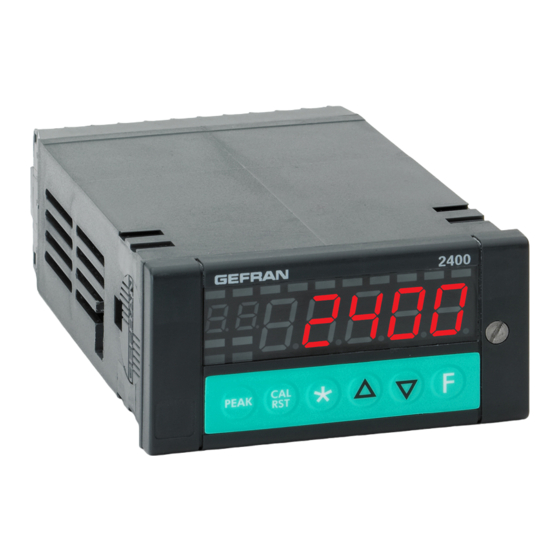
2400
FAST INDICATOR / INTERCEPTOR
GENERAL INDEX
Page
2
2
2
2
2
3
3
3
4
4
4
5
5
5
6
6
6
6
7
17
17
18
19
21
INSTALLATION AND
OPERATION MANUAL
Software version 1.4x
code 80290C / Edition 06 - 09/08 ENG
5
6
7
Accessories
RS232/TTL interface for Gefran
Instrument configuration
The contents of each section are summarized
immediately following the section heading
39
39
39
39
39
40
41
42
42
42
42
42
43
43
43
44
49
50
56
1
Advertisement
Table of Contents

Related Manuals for gefran 2400


Summary of Contents for gefran 2400
-
Page 1: Table Of Contents
Technical-Commercial information Instrument power supply Order code Inputs and outputs connection Dimensions and cut-out Accessories Installation with panel mounting RS232/TTL interface for Gefran Warnings and instructions for Instrument configuration mounting to the panel Nominal ambient conditions Appendix Electrical connections Block Diagrams... -
Page 2: Graphic Symbols Used
In particular, this • 2 digital inputs configurable NPN or PNP new line of Gefran indicators/alarm units is the ideal • 1 probe power supply selectable for strain gauge, solution for sectors demanding high performance and... -
Page 3: Operator Intefrace
Operator Interface Example: 2400 – 0 – 0 – 4R – 2 – 1 Model 2400 All the operator interface devices are concentrated on Single main input the controller faceplate with IP54 level protection. None retransmission output • 6 buttons to be used for regulation / manual selection 4 relay outputs •... -
Page 4: Installation And Connection
The instrument series 2400 are mainly designed to ope- (CE marking), to cut off the power supply upstream of rate in industrial environments, installed on the switch- the instrument. -
Page 5: Advice For Correct Installation For Emc
Direct Current. connection: - the voltage between neutral and earth must not be >1V GEFRAN S.p.A. declines all responsibility for - the Ohmic resistance must be < 6Ω; any damage to persons or property caused •... -
Page 6: Dimensions And Cut-Out
Example: 2400 – x – x – x – x – 1 = 100..240Vac/dc 2400 – x – x – x – x – 0 = 20..27Vac/dc 80290C_MHW_2400_0908_ENG... -
Page 7: Electrical Connections
Electrical Connections (Mod. 2400 - 0 - x - x - x - x) no/nc + OUT 3 no/nc OUT 2 OUT 4 no/nc + OUT 1 no/nc power supply 90-260Vac / 18-30Vac/dc + IN4 Rtd1 CAL1 + IN3 + 24V transmitter supply... - Page 8 Electrical Connections (Mod. 2400 - 0 - x - x - x - x) Input IN1 TC - Thermocouple Available thermocouples: J, K, R, S, T (B,E, N, L, U, G, D, C possible by inserting custom linearization) PT100 for possible...
- Page 9 Electrical Connections (Mod. 2400 - 0 - x - x - x - x) IN1 Linear input (I) IN1 potentiometer input Probe power supply 2,5V Linear input in DC 0/4...20mA, Ri = 50Ω Potentiometer R ≥ 100Ω IN1 Linear input (V) Linear input in DC ±...
- Page 10 Electrical Connections (Mod. 2400 - 1 - x - x - x - x) no/nc + OUT 3 no/nc OUT 2 OUT 4 no/nc + OUT 1 no/nc power supply 90-260Vac / 18-30Vac/dc + IN4 + IN3 + 24V transmitter supply...
- Page 11 Electrical Connections (Mod. 2400 - 1 - x - x - x - x) IN2 TC - Thermocouple input IN1 TC - Thermocouple input (*) PT100 for possible compensation of Available thermocouples: remote cold junction J, K, R, S, T...
- Page 12 Electrical Connections (Mod. 2400 - 1 - x - x - x - x) IN2 linear input (I) IN1 linear input (I) IN2 linear input (V) IN1 linear input (V) IN2 PT100 input 2-wire connection 3-wire connection Use wires with adequate...
- Page 13 Electrical Connections (Mod. 2400 - 1 - x - x - x - x) IN2 Strain-gauge input 4/6 wires Probe power supply 5/10V Green - Exc White + Exc Black or Yellow Blue Brown or Orange IN1 Strain-gauge input 4/6 wires...
- Page 14 Electrical Connections (for all models) IN3, IN4 linear inputs with 3-wire transmitter powered by instrument + 24V Transmitter power supply IN3, IN4 linear inputs with 2-wire transmitter powered by instrument + 24V Transmitter power supply IN3, IN4 linear inputs (I) IN3, IN4 potentiometer inputs Vpot 10Vdc (terminal 5)
- Page 15 Electrical Connections (for all models) Digital inputs DI1, DI2 Digital inputs (PNP), 24V, max. 5mA or voltage-free contact (NPN) max. 5mA Single selection PNP/NPN for DI1, DI2 by setting configuration parameter (Hd1 = +8) OUT 1, OUT 2, OUT 3, OUT 4 outputs no/nc + OUT 1 OUT 2...
- Page 16 Electrical Connections (for all models) Retransmission output 0/2...10V, ±10V, max. 25mA protection against short circuit 0/4...20mA, on load max. 500Ω Select type by means of configuration parameter. Serial line - MODBUS RS485 2-wires (standard) RS485 4-wires RS232 Rx + Rx - A (data +) Tx + B (data -)
-
Page 17: Functions
3 • FUNCTIONS This section describes the use and functions of the displays, lighted indicators and buttons making up the instrument 2400 operator interface. It therefore contains essential information for correct programming and configuration of the controllers. Operator interface Symbol... -
Page 18: General Operating Notes
General Notes on Operation Switching on and operating the controller Self-diagnostics • When switched on, the controller runs a self-diagnostics test. During the test, all segments of the display and the 7 lighted indicators flash. • If self-diagnostics detects no errors, the controller enters normal operating state 8 8 8 8 8 (Level 1). - Page 19 Navigating the Indicator/Interceptor Menus Keep this button pushed to scroll the menus in succession; release when the required menu appears. Push to access the parameters of the selected menu. Keep + pushed to return immediately to level 1. Display level 1 Menu In.
- Page 20 Menu Display information Jumper S9 on CPU board S9 ON ? (see section 6 - maintenance) Serial Communication Configuration InP. 1 of Input 1 Configuration InP. 2 of Input 2 Configuration InP. 3 of Input 3 Configuration InP. 4 of Input 4 Configuration of trip points Configuration...
-
Page 21: Configuration And Programming
To provide optimum functioning in its intended application, the the Configuration/Programming Section, and are a instrument 2400 control parameters have to be correctly confi- valuable consulting tool for the user. gured and programmed. - Page 22 I I n n F F Informations This menu lets you display the state of the instrument Software release Instrument code Err. 1 Error code IN 1 no error Err. 2 Error code IN 2 Err. 3 Ebr.Lo Error code IN 3 Er.rtd Er.CAL See: General notes on operation...
- Page 23 Serial Communication This menu lets you configure the various parameters that control serial communication between instrument and supervisor. Instrument Identification Code [0 ... 247] Baudrate 1200 bit/s 2400 bit/s 4800 bit/s Select Baudrate 9600 bit/s 19200 bit/s 38400 bit/s 57600 bit/s...
- Page 24 I I n n P P . . 1 1 Setting Input 1 This menu lets you configure parameters for the input 1 signals Probe type, signal, enable custom linearization, InP. 1 and main input scale. Probe type Scale limits Probe type Scale limits Potentiometer ≥100Ω...
- Page 25 I I n n P P . . 2 2 Setting Input 2 This menu lets you configure parameters for the input 2 signals Probe type, signal, enable custom linearization, InP. 2 and main input scale. Probe type Scale limits Probe type Scale limits Potentiometer ≥100Ω...
- Page 26 I I n n P P . . 3 3 Setting Input 3 This menu lets you configure parameters for the input 3 signals. InP. 3 Probe type Scale limits Input disabled 0...10V -19999/99999 Probe type, signal, enable custom tyP. 3 0...20mA -19999/99999 linearization, and main input scale...
- Page 27 I I n n P P . . 4 4 Setting Input 4 This menu lets you configure parameters for the input 4 signals. InP. 4 Probe type Scale limits Input disabled 0...10V -19999/99999 Probe type, signal, enable custom tyP. 4 0...20mA -19999/99999 linearization, and main input scale...
- Page 28 A A L L L L Setting Alarms This menu lets you configure parameters for the alarm functions. Reference quantity n. alarm Fin.A (math function A) Fin.b (math function b) n = 1 Value acquired from serial line Input 1 maximum peak Input 1 minimum peak Select reference quantities Input 1 peak - peak...
- Page 29 [ALL] MIN limit alarm setpoint Lo. A L [-19999 ... 99999] MAX limit alarm setpoint xi. A L [-19999 ... 99999] Alarm 3 Fault Action (definition of alarm state in case of broken probe Err, Sbr, Ebr) State of alarms 4...10 = OFF +16 for state of alarms 4...10 = ON 80290C_MHW_2400_0908_ENG...
- Page 30 0 0 v v t t Setting Outputs This menu lets you configure the output parameters. Function OUT 1 RL. 1 AL1 – alarm 1 Attribute reference signal AL2 – alarm 2 AL3 – alarm 3 Repeat logic input 1 Repeat logic input 2 Repeat but 1 key RL.
- Page 31 P P R R O O Protection Code This menu lets you enable/disable the display and/or change of certain parameters. (To access this menu, see the section “Using the controller menus”) Display Change In. 1 , In. 2 , In. 3 , , In. 4 AL.
- Page 32 [xrd] Function disabled Fin.A = ( ((C1.A * In1.A)^ C2.A) OPEr.A ((C3.A * In2.A)^ C4.A)) / C5.A Fvnc. A IN1 + IN2 Math function A IN1 - IN2 IN1 / IN2 [IN2 only with positive scale (1...99999)] Square root IN1 [IN1 only with positive scale (0...99999)] if Func.A = 1 (IN1 + IN2) / 2 IN3 * C1.A...
- Page 33 [xrd] Function disabled Fin.b = ( ((C1.B * In1.B)^ C2.B) OPEr.B ((C3.B * In2.B)^ C4.B)) / C5.B IN1 + IN2 Fvnc. b IN1 - IN2 Math function B IN1 / IN2 [IN2 only with positive scale (1...99999)] Square root IN1 [IN1 only with positive scale (0...99999)] (IN1 + IN2)/ 2 if Func.b = 1 IN3 * C1.B...
- Page 34 [xrd] Number of Alarms Enabled AL. n [0 ... 10] Function bvt. 1 Disabled (no function) Peak Key Function HOLD IN1 Reset memory latch Set / Reset outputs OUT 1 ... OUT 4 (for but.1 only) Peak ON + (maximum) IN1 bvt.
- Page 35 Function [xrd] Disabled (no function) HOLD IN1 Reset alarm latch Alarm limit 1 from input In.3 diG. 1 Digital input 1 function Alarm limit 2 from input In.4 Alarm limit 1 from input In.3 and alarm limit 2 from input In.4 Set / Reset outputs OUT 1 ...
- Page 36 [xrd] Select unit of measurement of physical quan- tity to be displayed on Display F in function at ds. F level 1 °C Select unit of measurement of physical quan- °F tity to be displayed on Display F in function at ds.
- Page 37 L L ' ' N N Input Linearization This menu lets you run custom linearization. Variable intervals (max 32) Variable intervals (max 32) self-learning from IN1 Variable intervals (max 32) self-learning from IN2 Linearization type Variable intervals (max 32) [0 ... 5] self-learning from IN3 tyP.
- Page 38 U. ( AL which calibration is maximum calibration U. ( AL phase 1 (Least Significant Word) Potx. L maximum calibration phase 2 (Most Significant Word) Potx. x U. ( AL Note.: only for model with a single input: 2400-0-... 80290C_MHW_2400_0908_ENG...
-
Page 39: Application Notes
Application Notes HOLD Function The input value and alarms are frozen while the logic input is closed. With logic input closed, a reset turns OFF both the relay outputs and the alarms latch. FLASH function The input value is sampled, the setpoints are “frozen”, when the logic input switches on the input value is “frozen” and the setpoints are updated based on the last acquired value. -
Page 40: String Assigned To An Alarm
String assigned to an alarm Each enabled alarm can be assigned an alphanumeric string composed of 5 characters, to be displayed on the PV in level 1. The string of alarm n (with n from 1 to 10) is enabled by means of parameter At.n = +512 (to display the string when the alarm trips) or At.n = +1024 (to display the string when the alarm limit is exceeded in case of alarm with time delay). -
Page 41: Technical Specifications
5 • TECHNICAL SPECIFICATIONS This section contains a list of the Technical Specifications for the instrument 2400. Display 1 x 5 red/green bicolor digits, height 13mm 1 x 2 red digits, height 7mm 14 x red led Keys 6 mechanical keys (Peak, Cal/Rst,... -
Page 42: Maintenance
When it is switched on again a self- illegible diagnostic test is performed that checks intermittent start up of all the segments (displays the value 88888). If one or more segments do not light up contact your Gefran dealer. When pressing down none... -
Page 43: Technical-Commercial Information
Gefran Customer Care Service is contacted for assistance with any problems. Order code – Indicator / Interceptor 2400... -
Page 44: Appendix
APPENDIX Display Default CONF Description Menu MAIN PU / SU / F In. 1 Input IN 1 main In. 2 Input IN 2 main In. 3 Input IN3 auxiliary In. 4 Input IN4 auxiliary Fin. A Result math function A Fin. - Page 45 Display Default CONF Description Menu I I N N P P 4 4 typ. 4 Type of probe or signal for input IN4 Flt. 4 Digital filter input IN4 dPs. 4 Decimal point position for IN4 LoS. 4 Min. scale limit input IN4 xiS.
- Page 46 Display Default CONF Description SdE. 6 Character E alarm string 6 Ar. 7 Alarm reference 7 At. 7 Type alarm 7 xy. 7 Alarm hysteresis 7 rA. 7 Activation time alarm 7 bt. 7 Time base for activation time alarm 7 Sda.
- Page 47 Display Default CONF Description (4. A Coefficient (4. A (5. A Coefficient (5. A Fvnc. b Math function b In1. b First operand of Fvnc. b In2. b Second operand of Fvnc. b 0pEr. b Operator of Fvnc. b (1. b Coefficient (1.
- Page 48 Display Default CONF Description Menu L L i i n n tyP. L Type linearization StEP. n Number segments S. 0 0 (S. 0 0) Segment 0 low scale linearized value (Step 0) S. 0 1 A (S. 0 1) Segment 1 input value [1/10.000] f.s.
-
Page 49: Block Diagrams
DISPLAY / KEYBOARD OUTPUTS OUT1,...,OUT4 RELAYS MAIN INPUTS IN1, IN2 PROBE POWER SUPPLY RETRANSMISSION AUXILIARY INPUTS OUTPUT OUT W IN3, IN4 TRANSMITTERS POWER SUPPLY A/D CONVERTER DIGITAL COMMUNICATION DIGITAL INPUTS RS485 DI1,...,DI2 LOGIC OUT1,...,OUT4 OUTPUTS POWER SUPPLY 20...27Vac/dc 100...240Vac/dc isolation 1,5KV isolation 4KV... -
Page 50: Functional Diagram
tyP1 HiS.1-LoS.1 INPUT 1 probe type OFS.1 FiLt.1 enable custom linear. dP.1 peak IN1 max detector but 1...3 IN1 min DI 1, 2 NETTO / tare sampling LORDO but 1... 3 IN1 tare but 1... 3 DI 1, 2 DI 1, 2 tyP2 HiS.2-LoS.2 INPUT 2... - Page 51 Fin.A = ( ((C1.A * In1.A)^ C2.A) OPEr.A ((C3.A * In2.A)^ C4.A)) / C5.A IN1...4 where OPEr.A = +,-,*,/ In1.A Fin.b Func.A Fin.A IN1...4 In2.A Fin.b Fin.b = ( ((C1.b * In1.b)^ C2.b) OPEr.b ((C3.b * In2.b)^ C4.b)) / C5.b IN1...4 where OPEr.b = +,-,*,/ In1.b...
- Page 52 IN1 max Peak IN1 max - IN1 min detector IN1 min IN2 max Peak IN2 max - IN2 min detector IN2 min RETRANSMISSION OUTPUT Fin.A HiS.An tyP.An RiF.An LoS.An Fin.b AL.1 AL.2 AL.3 Remote digital retransmission...
- Page 53 IN1 max Peak IN1 max - IN1 min AL.1 Stato AL1 detector At.1 IN1 min AL.2 IN2 max At.2 Stato AL2 Peak IN2 max - IN2 min detector IN2 min . . . Fin.A Fin.b Ar.1 . . . Ar.2 Ar.3 Ar.4 Ar.5...
- Page 54 Diff Pot > 100Ω INPUT 1 External Power supply Control compensation cold third wire Rtd 6-wire pressure junction temperature probe calibration Power supply potentiometer 2,5V Diff Pot > 100Ω INPUT 2 Control External Power supply 6-wire pressure compensation cold third wire Rtd Power supply probe calibration junction temperature...
- Page 55 NO/NC Relay 5A 250Vac/30Vdc OUT 1, ..., OUT 4 Logic Source/Sink 30mA, Ru = 390Ω MD8 interface (alternative to OUT 3, OUT 4) RETRANSMISSION 0/2...10V OUTPUT 0/4...20mA...
-
Page 56: Examples Of Custom Linearization
EXAMPLES OF CUSTOM LINEARIZATION Example of custom linearization: type 0 (at variable amplitude intervals, max. 32) For positive polarization signals (ex. 0...50mV) S. 0 0 is the value displayed for minimum input (ex. 0mV); if 32 intervals are set, S. 3 2b is the value displayed for input = S. 3 2A * (f.s. / 10000) (ex.
Need help?
Do you have a question about the 2400 and is the answer not in the manual?
Questions and answers