Advertisement
Quick Links
1 • INSTALLATION
• Dimensions and cut-out; panel mounting
108
96
48
44,5
105
10
Panel mounting:
Fix the device with the bracket provided before making any electrical
connections.
To mount two or more devices side by side, use the cut-out dimensions
shown above.
CE MARKING: The instrument conforms to the European Directives
2004/108/CE and 2006/95/CE with reference to the generic standards:
EN 61000-6-2 (immunity in industrial environment) EN 61000-6-3 (emission
in residential environment) EN 61010-1 (safety)
MAINTENANCE: Repairs must be done out only by trained and
specialized personnel. Cut power to the device before accessing
internal parts.
Do not clean the case with hydrocarbon-based solvents (Petrol,
Trichlorethylene, etc.). Use of these solvents can reduce the
mechanical reliability of the device. Use a cloth dampened in ethyl
alcohol or water to clean the external plastic case.
SERVICE: GEFRAN has a service department. The warranty excludes
defects caused by any use not conforming to these instructions.
EMC conformity has been tested with the following connections
FUNCTION
TC input probe
"PT100" input
probe
Power supply cable
Relay output cables
81641I_MHW_40T96_07-2011_ENG
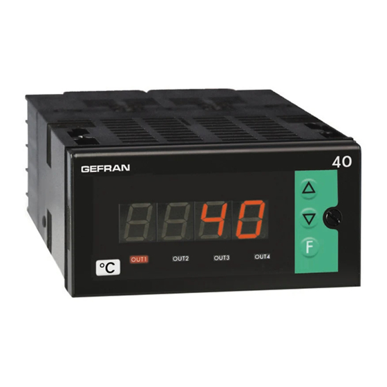
40T 96
UNIVERSAL TEMPERATURE and PRESSURE INDICATOR - ALARM UNIT
115
92
!
For correct and safe
installation, follow
the instructions and
observe the warnings
contained in this
manual.
CABLE
LENGTH.
USED
0,8 mm
compensated
5 mt
2
1 mm
3 mt
2
1 mm
1 mt
2
1 mm
3,5 mt
2
INSTALLATION and
OPERATION MANUAL
SOFTWARE VERSION 3.2x
code 81641I / edition 15 - 07-2011
TECHNICAL SPECIFICATIONS
2 •
Display
Keys
Accuracy
Thermal drift
Resolution
(unction of settable sample
time)
Main input
70
Thermocouples
Cold junction error
RTD type (scale configurable
within indicated range, with or
without decimal point)
Max. RTD line resistance
PTC type / NTC type
Max non-linearity error
°C / °F selection
Linear scale range
Logic input
Function of logic
input
Alarms
(Trip points)
Alarm
masking
Relat contact
Logic output
Triac output
Fault settings
Transmitter / Sensor power
Supply (option)
Analog retransmission
(option)
Power supply
(switching)
Fuse (inside device, not
operator serviceable)
Faceplate protection
Working / Storage temperat.
Relative humidity
Environmental conditions of use
Installation
Weight
(includes R77 version)
3, 4 digit red LED's digit height 20mm (3 digits),
digit height 14mm (4 digits)
3 mechanical keys (Raise, Lower, F)
0.2% f.s. at 25°C, amb. temperature ts
=120msec
0.005% f.s./°C
120msec, >14bit
60msec, >14bit
(only for linear inputs)
30msec, >13bit
(only for linear inputs)
15msec, >12bit
(only for linear inputs)
TC, RTD, PTC, NTC
60mV, 1V Ri ≥ 1MΩ; 5V, 10V Ri ≥ 10KΩ
20mA, Ri = 50Ω. adjustable digital filter
J, K, R, S, T, B, E, N (IEC 584-1, CEI
EN 60584-1, 60584-2) L GOST, U, G, D, C.
Custom linearization available on request
0,1° / °C
DIN 43760 (PT100), JPT100
20Ω
990Ω, 25°C / 1KΩ, 25°C
See tP parameter
Faceplate configurable
-1999...9999 (with 4 digit display)
-999...999 (with 3 digit display); punto
Configurable decimal point position, possible
3 segment linearization
24V, 5mA or no-voltage contact
configurable to reset memory latch, hold,
flash, zero, select max./ min. peak, peak-
peak value
Maximum of three configurable alarms:
absolute, deviation, symmetrical deviation.
Adjustable hysteresis
- exclude on power-up
- latch reset from key and/or external contact
- insert delay filter (DON, DBI, DOF, DPO)
- set minimum intervention time
NO (NC) 5A 250Vac, 30Vdc
24Vdc, 10V at 20mA, limitation to 30mA
20...240Vac ±10%, 3A max. Snubberless,
inductive and resistive load I
t = 128A
2
Alarm states can be configured in probe
fault condition
24V ±10%, 50mA
15V for transmitter, max. 50mA
1,2V for potentiometer > 100Ω
10V Rmin 50K - 0/4...20mA Rmax. 500Ω
resolution 12bit
(std) 100...240Vac/dc ±10%, 50/60Hz, 18VA
(opt) 11...27Vac/dc ±10%, 50/60Hz, 11VA
100 to 240VAC/DC -type T-500mA-250V
11 to 27VAC/DC - type T - 1,25A - 250V
IP65
0 to 50°C / -20 to 70°C
20 to 85% Ur non condensing
for internal use only, altitude up to 2000m
Panel mounting, extractable from front
320 g for the complete version
S
2
1
Advertisement

Related Manuals for gefran 40T96

Summary of Contents for gefran 40T96
- Page 1 Supply (option) 15V for transmitter, max. 50mA SERVICE: GEFRAN has a service department. The warranty excludes 1,2V for potentiometer > 100Ω defects caused by any use not conforming to these instructions.
-
Page 2: Description Of Front Panel
3 • DESCRIPTION OF FRONT PANEL “Raise” and “Lower” keys: These keys are used for any operation that requires a numerical parameter to be raised or lowered. •• The speed of change is proportional to the time the key is pressed. •• The operation is not cyclic: once the maximum (minimum) limit Function key: is reached, there will be no further increase... -
Page 3: Digital Input
Connections for keylock function through digital input (require selection +VT for the signal on contact 3) OFF (open): keyboard enable ON (closed): keyboard disable User configurable generic outputs / inputs ANALOGUE Output DIGITAL Input - Analogue 0...10V, 0/4...20mA - Digital input 24V 5mA (Jumpers S1, S2 in - 0/2...10V (S1-ON), position P) or from non-powered terminal 0/4...20mA (S1-OFF) -
Page 4: Programming And Configuration
5 • PROGRAMMING and CONFIGURATION LEVEL 1 DISPLAY Pressed for approx. 2 sec. P. U . Process variable Information display o. 1 Alarm Setpoint Output 1 JUMPER S4 (CPU) =ON o. 2 Alarm Setpoint Output 2 Hysteresis parameters o. 3 Alarm Setpoint Output 3 Serial communication o. - Page 5 Inputs Unit identification code 0...247 Set code 48 in S.I to manage serial line PV and IN SP Serial protocol s. p Serial interface protocol CENCAL Gefran MODBUS RTU S. o Virtual instrument outputs 0...31 bA Baudrate Select Baudrate Outputs...
- Page 6 • TC/LIN input parameters Input settings 120ms > 14bit Select sampling time (. 1 . 60ms > 14bit (resolution). For linear 30ms > 13bit Type of probe, input 0...1V/POT only. t. P 15ms > 12bit signal and scale of main input +4 to disable filter (average of the last eight values sampled) TYPE...
- Page 7 • Output parameters • Custom linearization Custom linearization of Output settings main input Step 0 Display limits Number of outputs 0 to 4 0. 0 . (beginning of scale value) (-1999 to 9999 for 4 digit display) the n step value corresponds to input: Alarm type 1 1.
- Page 8 • HOLD function The input value and alarms are frozen while the logic input is closed. With logic input closed, a reset turns OFF both the relay outputs and the alarms latch. • FLASH function Input value is sampled; state of alarms is not transferred to outputs; outputs are “frozen”. When the logic input is active the input value is “frozen”...
- Page 9 • Interface for GEFRAN instrument configuration Kit for PC via the USB port (Windows environment) for GEFRAN instruments configuration: KIT PC USB / RS485 o TTL Lets you read or write all of the parameters • A single software for all models •...
- Page 10 VAC. Resistors must be at least 2W); fit a 1N4007 diode in parallel with the coil of inductive loads that operate in DC. GEFRAN spa will not be held liable for any injury to persons and/or damage to property deriving from tampering, from any incorrect or erroneous use, or from any use not conforming to the device specifications.
Need help?
Do you have a question about the 40T96 and is the answer not in the manual?
Questions and answers
Jak zaprogramować gefran 40T
To program the Gefran 40T96, follow these steps:
1. Access the Programming Menu:
- Use the three mechanical keys on the front panel: *Raise*, *Lower*, and *F*.
2. Function Blocks:
- The parameters are grouped into function blocks, making it easier to navigate and set up.
3. Simplified Data Entry:
- The data entry menu is simplified to facilitate programming.
4. PC Programming Kit (Optional):
- You can use a PC programming kit software compatible with Windows to further simplify the configuration process.
5. Password Protection:
- Set a password if needed to restrict editing of configuration parameters.
6. Input Configuration:
- No external shunt or adapter is required. Configure the correct input contact according to your needs.
7. Alarms and Outputs:
- Configure up to three alarms with customizable functions.
- Available control outputs include relay, logic, triac, or continuous.
For more detailed instructions, refer to the installation and operation manual.
This answer is automatically generated
How to connect this indicator through to PLC and Melt pressure transmitter