Table of Contents
Advertisement
Advertisement
Table of Contents

Related Manuals for Culligan GBE

Summary of Contents for Culligan GBE
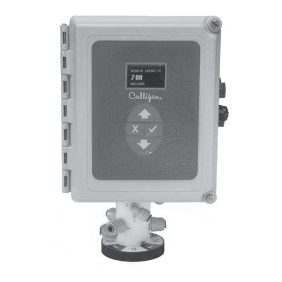
- Page 1 Cat. No. 01021161 Rev. A 10/16/08 DCO # 010703 Installation, Operating and Service Instructions CULLIGAN ® Global Electronic (GBE) Softener & Filter Controller For Commercial/Industrial Applications Models from 2008 ©2008 Culligan International Company Printed in USA...
- Page 2 Products manufactured and marketed by Culligan International Company (Culligan) and its affiliates are protected by patents issued or pend- ing in the United States and other countries. Culligan reserves the right to change the specifications referred to in this literature at any time, without prior notice.
-
Page 3: Table Of Contents
Operating and Service Instructions CULLIGAN ® GLObAL ELECTRONIC (GbE) SOFTENER & FILTER CONTROLLER Table of Contents ....Page Installation of Accessories ........33-45 Aqua-Sensor ............33 Beeper Mode ............33 Important Safety Information ........ -
Page 4: Controller Features
Controller Features The Culligan Global Electronic control (GBE) primary function is to initiate and control the regeneration process via methods that are most convenient and cost effective for the customer while offering many operational features and benefits. The controller is designed to operate a wide range of existing and new softener and filtration valves. -
Page 5: Controller Features
• Wireless Remote Display Displays the current status of the unit. It can be located up to 200 feet away from the GBE controller (depending on building and interference). The telephone modem can optionally be installed in the remote display •... -
Page 6: Operation
Differential Pressure (Filters only) When combined with an optional differential pressure device, the Culligan MVP controller has the ability to initiate a backwashing sequence when the pressure differential across the media bed reaches a preset amount (usually 8 to 10 psi). -
Page 7: Installation
Provide a dedicated 120-volt circuit for the GBE system to ensure maximum electrical protection. DO NOT include the GBE wiring cables in any conduit or raceway containing other 120-volt or higher circuits. Maintain a distance of at least 10 feet between the GBE controller and any electrical distribution panels, raceways carrying 300 volts or more, and electrical motors of 1 horsepower or more. - Page 8 2. Using a small screwdriver, loosen all the terminal strip binding screws on the main circuit board that do not contain wires by turning counterclockwise until the wire clamp has been fully opened (see Figure 5). Figure 4 Figure 3 Figure 5 CULLIGAN GLOBAL ELECTRONIC CONTROLLER...
- Page 9 Installation Cable Routing All input and output connections to the circuit board are 24 volt or less. Although the cables do not have to be run in conduit, it is necessary that long runs of cable be supported or protected by strapping them to the equipment piping. If conduit will be used to route the shielded cables, three factors must be considered: 1.
-
Page 10: Wiring Schematics
Schematic – GbE Circuit board Layout Front OLED Display Battery CR2032 (Postitive Side Up) Keypad connector Figure 8 – GbE Circuit board Layout back Data port Phone line connection (optional) Future use Do not connect Motor position cable anything to these Multiple unit jumper... -
Page 11: Transformer
Schematic Outputs The circuit board supports four outputs: CAUTION • Motor control (DC Motor) Connecting 24V to the 2.5v • Blocking valve (Use Aux Out 4) connection on the circuit board • Four programmable auxiliary outputs (Aux Out 1 will damage the circuit board. through 4) •... -
Page 12: 24V Transformer
2. Repeat the process for the other 24V power supply wire attaching the second wire to the opposite terminal on the transformer and next to the other wire connected to the 24V pins on the GBE board. 24V Power Connection... -
Page 13: Brine Refill Valve
Schematic brine Refill Valve Wiring *This only applies to Culligan CSM Softeners. 1. Installation of the solenoid coil and connector Locate the solenoid coil and connector cord. Assemble it to the brine refill valve as shown in Figure 13. Solenoid... -
Page 14: Communication Cable
These solenoids are included in the alternating and progressive flow kits. blocking Solenoid Connection (used on Alternating and Progressive flow systems) The solenoid valve wiring attaches to the Aux Out 4 output connection on the auxiliary circuit board. See Figure 16 . S OL Figure 16 CULLIGAN GLOBAL ELECTRONIC CONTROLLER... -
Page 15: Progressive/ Parallel Flow
Progressive/Parallel Communication Cable 01016327 To RS 485 Comm Port To RS 485 Comm Port Additional communication cable on GBE Circuit Board, #1 on GBE Circuit Board, #2 connections are used when there are 3 or more controls. Connect end of 2nd-(01016327) cable... - Page 16 For triplex, quad, etc alternating, you must use a meter on each unit and connect the same way as progressive flow. Duplex Alternating Cable 01016342 To RS 485Comm Port To RS 485Comm Port on GBE Ciruit Board, #2 on GBE Ciruit Board, #1 To Flow Meter Connection (on GBE Circuit Board). Flow Meter Connector To Flow Meter Connection (from meter).
-
Page 17: Flow Meters
Schematic Flow Sensor Meter Connections (Optional) The GBE Controller is capable of detecting the signal from a Hall effect sensor device to provide flow rate infor- mation, totalization and volume based regeneration initiation. There are several different types of flow measuring devices and differences in the wiring of the devices to the GBE circuit board do exist. -
Page 18: Aqua-Sensor
GBE circuit board. The wire connector from the Aqua-Sensor probe is then routed through the included cable grip and plugged into the Aqua-Sensor terminal on the GBE circuit board. See below. Aqua-Sensor If you are going to install an Aqua-Sensor, you can set up the 2.5V power now. -
Page 19: Aux Outputs
Schematic Auxiliary Outputs (Optional) The Auxiliary Outputs - reference Figure 21) are output triacs that can be programmed to provide power to a “normally open” (normally no power to auxiliary output until power required) or a “normally closed” contact (user choice). -
Page 20: Aux Input
Connect this contact to the Aux In terminal shown in Figure 22. The illustration below is an example of how to use an external source to initiate regeneration. Communication Cable 01016327 POLE EXTERNAL SOURCE POLE Regen Signal 24V DPDT RELAY Figure 22 DUPLEX ALTERNATING WITH EXTERNAL SOURCE CULLIGAN GLOBAL ELECTRONIC CONTROLLER... -
Page 21: Programming
To determine the batch set point for programming the Culligan GBE controller, use the following formula: Total Capacity - Reserve Capacity Gallons = Hardness The GBE will calculate this for you automatically. you can use the formula above to verify the setting. For more information on programming multi-tank systems, see page 41. Programming... -
Page 22: Key Pad Operation
Programming Program Data Input There are a couple of items to note that can make the programming of the Culligan GBE control a little easier. They are: Slew Rates This term refers to the speed at which the display moves through the input of material. For example, holding down the up arrow key for (5) seconds when inputting minutes for Time... - Page 23 Navigating the Menus and Keypad This is the “home” screen. system ok Press any key except 9:17 am 1-17-08 CANCEL (“x”) takes you to the main menu. > 1) information 2) bypass UP button 3) regenerate 4) set time and date This is the main menu.
-
Page 24: Overview
Programming GbE Controller Programming The programming for the GBE controller is all menu based. There are 5 top level menus with additional options below each. The top 5 are: 1) INFORMATION 2) MANUAL MODE 3) SET DATE / TIME 4) ACCESSORIES 5) ADVANCED SETUP Here is a brief explanation of what you will find under each menu... -
Page 25: Commercial Setup
Programming Typical Commercial Setup Setting up the GBE for a commercial installation requires a few additional steps. Follow the outline below to make sure everything is covered. 1) Run the first time setup (see pages 24 to 27) 2) Set up accessories (see pages 33) This includes: •... -
Page 26: First Time Setup
Note: If this unit will be installed with a modem, it is required that this electronic ID number is reported back to Culligan on the IQR form. Press the DOWN arrow button to change the display to read “Set Month”. - Page 27 First Time Setup Process Set Month • The “>” symbol indicates that this value may be changed by pressing the UP and DOWN arrow buttons. For example, pressing the DOWN arrow > FEB while the “>” mark is displayed changes the display from “JAN” to “FEB”. •...
- Page 28 “>” symbol next to the displayed value. Use the UP or DOWN arrow to change the setting. Once the desired value is displayed, this value can be accepted by pressing the “CHECK MARK” button. Press the DOWN arrow to accept that value and move to the next question. CULLIGAN GLOBAL ELECTRONIC CONTROLLER...
- Page 29 First Time Setup Process 11. Set Units (US-inch or metrics) units us-inch • If the value displayed is NOT correct, pressing the “CHECK MARK” button will change the display, to show a “>” symbol next to the displayed value. Use the UP or DOWN arrow to change the setting. Once the desired value is displayed, this value can be accepted by pressing the “CHECK MARK”...
-
Page 30: First Time Setup
The circuit board microprocessor automatically calculates softener capacity. The control then automatically homes. Contact your Culligan Man if the settings need to be customized. Note: For all commercial applications, you must adjust the cycle times. Most important is refill time. Refer to the Brine System charts in the product’s installation manual for cycle settings. -
Page 31: Customizing The Setup
Customizing the Setup The controller is designed to simplify the setup and installation process by making some default recommendations during the Initial Setup. The default settings are designed to be appropriate for most common installations. Default Settings • Downflow Brining •... -
Page 32: Progressive Flow
Customizing the Setup The GBE controller can operate several types of valves. Select from 4-CYCLE, 5-CYCLE or GBV. valve type For Softeners: For Filters: 4-cycle CSM and Hi-Flo 50 are 5-CYCLE All are 4-CYCLE Hi-Flo 22 and Hi-Flo 3e are 4-CYCLE The type of resin changes how the GBE calculates capacity. -
Page 33: Regeneration
Customizing the Setup Regeneration Set-up Press the UP „ or DOWN ‰ arrow to scroll to menu item • Press the CHECKMARK key to select a menu item • UP „ DOWN ‰ arrow to change a selection • Press the Press the CHECKMARK key to save your selection •... -
Page 34: Cycle Times
For a 4-cycle valve, the refill is controlled by AUX OUTPUT 2 and the refill time is set there. See page 46. This concludes the Cycle Times section. Continue to press the X key to return to the Main Menu. CULLIGAN GLOBAL ELECTRONIC CONTROLLER... -
Page 35: Regeneration Triggers
Customizing the Setup Regeneration Triggers Press the UP „ or DOWN ‰ arrow to scroll to menu item • Press the CHECKMARK key to select a menu item • UP „ DOWN ‰ arrow to change a selection • Press the Press the CHECKMARK key to save your selection •... -
Page 36: Installation Of Accessories
CHECK MARK BEEPER MODE . Press the when the correct displayed. key Press Beeps Beeps on Alarm Always ON Always Always Always OFF Never Never 12 hour mode Never Between 8AM-8PM 24 hour mode Never Always CULLIGAN GLOBAL ELECTRONIC CONTROLLER... -
Page 37: Smart Brine Tank Sensor
Installation of Accessories Installing the Smart Brine Tank (SBT Probe) in to the Brine Tank 1. Place the smart brine probe on top of the brine plate as shown in Figure 24 . 2. Loop the two zip ties thru the holes in the probe housing and loop the zip ties around the outside of the brine well as shown in Figure 25. - Page 38 If modem has been installed in the remote, it is also necessary to follow the directions in the next section of this manual to configure the main controller to use the modem in the remote. 5 3/8” MODEM CONNECTION SCREWS POWER CONNECTION Figure 27b Figure 27a Back of GBE Board RF Board (Note orientation) Figure 28 CULLIGAN GLOBAL ELECTRONIC CONTROLLER...
-
Page 39: Wireless Remote
Installation of Accessories Control Valve Set-up system ok 7:32 am 2-1-08 From the home screen, press the DOWN arrow to ACCESSORIES. Press the CHECK MARK > 4) accessories button. Press the DOWN arrow to scroll to WIRELESS REM. > 6) wireless rem Press the CHECK MARK button to change REMOTE DISPLAY setting. - Page 40 ONLY available on units which have the modem installed on the main controller. Before installing the modem into the back of the GBE board or the back of the remote, the GBE circuit board or the remote must first be powered off.
- Page 41 Installation of Accessories Installing in GBE Board Open the controller cover and locate the modem connection on the back of the board (see figure 29). Insert line modem board (P/N 01020307) into the socket on the back of the board. Make sure that all of the pins in all four connectors are aligned and make sure the modem is fully seated into all of the sockets.
-
Page 42: Modem
GMT time. The “GMT offset” for some common cities are listed below: GMT Offset New York -5:00 (and anywhere in EST) Chicago -6:00 (CST) Denver -7:00 (MST) Los Angeles -8:00 (PST) London 0:00 Paris 0:00 Rome +1:00 CULLIGAN GLOBAL ELECTRONIC CONTROLLER... - Page 43 This menu attempts to send in a “test message”. The screen indicates whether or not this process is successful. Sending a “test message” will also update the time and date on the GBE controller to the correct time. If the modem is installed on the main controller (as opposed to installed in the remote control) then this testing process will also check to see if there is an updated version of firmware available on the Culligan servers.
-
Page 44: Low Meter
From the home screen, press the DOWN arrow to ACCESSORIES. Press the CHECK > 5) adv setup MARK button. Press the DOWN arrow key to scroll to SYSTEM SETUP and press the CHECK MARK > 1) system setup button. CULLIGAN GLOBAL ELECTRONIC CONTROLLER... -
Page 45: Brine Reclaim
5 slaves connected to a master. NOTE: PARALLEL OPERATION: To set up the GBE for parallel operation (all online), set the trip point to zero (0). As long as the flow is above zero, all units will stay online. - Page 46 Can be set to NORMALLY OFF or NORMALLY ON. For brine reclaim, set to aux3 cycle type NORMALLY OFF. normally off aux out 3 This can be set to any cycle. For brine reclaim, change this to BRINEDRAW POS. service pos CULLIGAN GLOBAL ELECTRONIC CONTROLLER...
-
Page 47: Service Phone Number
If the Modem is not installed it is possible, in addition to displaying the error message, to display a message that reads “Call Culligan at: XXXXXXXXXX” where the telephone number XXXXXXXXXX can be programmed by the dealership (typically programmed to be the telephone number of the dealership). This number is programmed under the menu: Main Menu / Accessories / Service Phone. -
Page 48: Installation Of Accessories
Press the CHECK MARK button to change FILTER CAPACITY setting. Press the UP or filter capacity DOWN arrow to increase or decrease FILTER CAPACITY. Press the CHECK MARK >10000 gallons when the correct FILTER CAPACITY is displayed. CULLIGAN GLOBAL ELECTRONIC CONTROLLER... -
Page 49: Auxiliary Boards
Auxiliary Contacts Auxiliary Board The auxiliary board comes installed in all commercial equipment. It can control up to four, 24 VAC outputs (max current 2.1 amps output). Aux Output 1 is used to power the 24 VAC drive motor found on all valves. When Aux Output 1 is used for this, then Aux Output 4 is automatically configured to operate a solenoid which can be used for a standby or blocking. - Page 50 No delay is necessary. delay 0 mins aux2 out For our example, this would be set to 17. on 0 mins AUX OUTPUT 3 has the same menu options. Refer to the chart on page 48 for quick reference. CULLIGAN GLOBAL ELECTRONIC CONTROLLER...
- Page 51 Auxiliary Contacts To use the auxiliary contacts, some configuration settings system ok must be changed. 7:32 am 2-1-08 From the home screen, press the DOWN arrow to > 4) Accessories ACCESSORIES. Press the CHECK MARK button. Press the DOWN arrow key to scroll to AUX IN. >...
-
Page 52: Manual Regeneration
NOTE: In multi-tank systems, the regeration request is sent to the master control and it will allow the unit to regerate at the next availble time. Press the “CANCEL” button to return to the “home” screen. CULLIGAN GLOBAL ELECTRONIC CONTROLLER... -
Page 53: Manual Cycling
Manual Cycling Manual cycling can be performed when the unit is starting either in SERVICE or while it is already within any portion of the REGENERATION process. If the unit is currently regenerating, the name of the current cycle position and the number of minutes remaining in the current cycle position will be displayed. -
Page 54: System Information
Press DOWN arrow to view next screen. next regen on Displays the date when the next regeneration will occur (based on average daily water usage). Press DOWN arrow to view next screen. today’s usage Displays today’s water usage. 115 gallons CULLIGAN GLOBAL ELECTRONIC CONTROLLER... - Page 55 Information Press DOWN arrow to view next screen. average daily Displays average daily water usage. 275 gallons Press DOWN arrow to view next screen. ext filtr cap rem Displays how many gallons remain before the optional filter cartridge needs to be 10,000 gallons replaced.
-
Page 56: Error & Alert Codes
MARK” on the keypad will display the detected error condition(s). Some of these messages will also provide ad- ditional information to help correct the error. The following error messages may display on both the GBE controller display as well as the Remote Display (if one is connected:) If the words “PROBLEM FOUND”... -
Page 57: Diagnostics / Statistics
Diagnostics There is a large number of diagnostic menu screens to aid in setup and troubleshooting of the GBE. Below is an overview of the menus. Advanced Statistics system ok 7:32 am 2-1-08 From the home screen, press the DOWN arrow to ADV. SETUP. Press the CHECK >... -
Page 58: Check Sensors
AQUASENSOR SUPPLY VOLTAGE: This will be either PASS or FAIL. If this reading is FAIL, aquasensor supply voltage check the Aqua-Sensor connection to the circuit board and to the power supply. Press DOWN 2.5vac: pass arrow to view the next statistic. CULLIGAN GLOBAL ELECTRONIC CONTROLLER... - Page 59 Diagnostics AQUASENSOR: Troubleshooting statistics. aquasensor • z-Ratio (impedance ratio) - Number calculated by microprocessor on measured voltage zratio 1.075 values that are converted to a digital representation. This is the value that the control zminimum 1.070 monitors in order to determine need for regeneration and salt rinse-out. 0.75% increase •...
- Page 60 3,4, and 5 will remain all zeros since no other slaves are connected. 5:0000, Tx: 0000 See page 50 Motor Control See Appendix C, page 65 Use Data Port See page 40 Test phone line IGNORE THIS Test wc app CULLIGAN GLOBAL ELECTRONIC CONTROLLER...
-
Page 61: Menu Lockout
Menu Lockout It is possible to lock the keypad of the GBE controller so that users will only have access to the INFORMATION, MANUAL MODE, and SET DATE/TIME menu screens. The system can be locked by pushing the up and down arrow keys simultaneously and holding them down for 10 seconds. -
Page 62: Menu Flow Chart
Menu Overview Continued on page 61 CULLIGAN GLOBAL ELECTRONIC CONTROLLER... - Page 63 Menu Overview Menu Overview...
- Page 64 Menu Overview Continued from page 59 CULLIGAN GLOBAL ELECTRONIC CONTROLLER...
- Page 65 Menu Overview Menu Overview...
-
Page 66: Appendix A - Meter K-Factors
56.8 Brazolet 2.5” 4.0 - 264 37.6 142.3 -Sch 40 Copper Pipe 3” 6.2 - 411 24.3 -Sch 40 Bronze Pipe 4” 10.8 - 716 13.9 52.6 -Sch 40 Brass Pipe Weldolet -Sch 40 Steel Pipe CULLIGAN GLOBAL ELECTRONIC CONTROLLER... -
Page 67: Appendix B - Parts & Accessories
Item Complete Controls 01020677 GBE Controller Complete for CSM, HF50 Softener GBE Controller Complete for CSM, HF42, HF50 Filter Hi-Flo 22 Softener Control Valve with GBE Controller Hi-Flo 22 Filter Control Valve with GBE Controller HF3e Conversion Kit – 2”... -
Page 68: Appendix C - Plc Output
“status messages” to a customer’s equipment using RS-232 and RS-485 communication protocols. These protocols are commonly used to send information from the GBE to either a customer’s PC or to a building management system or programmable logic controller (PLC). The information is “one-way” in that the GBE can send this information out, but the GBE cannot receive or respond to any commands sent into the communication port. - Page 69 So the value of the error flag would be 0x0150 if these three errors were present. NOTE: If the GBE is controlling a Filter (instead of a water softener) then the above message definitions are identi- cal, but that error flags 1,2,3,6,9 and 11 will always be zero for a filter) Progressive Flow System of Water Softeners controlled by GBE: The format of the “status message”...
- Page 70 Function 3 (input) TD (data coming FROM the GBE board) 2 (output) RD (this line is required even though no data is sent TO the GBE board) 7 (input) 8 (output) 5 (signal gnd) The data coming from the GBE board is at the following conditions:...
- Page 71 Appendix C Return to the GBE controller and press the Down Arrow to enter the Menu. Using the down arrow, scroll down to number 5, Advanced Setup, and press the checkmark. Using the down arrow, scroll to number 5, Diagnostics, and press the checkmark.
-
Page 72: Appendix D - Control Settings
Appendix D CULLIGAN GLOBAL ELECTRONIC CONTROLLER... -
Page 73: Index
Index Accessories 33-45 Setup - Customizing 28-34 Alternating 3, 11, 13-14, 17, 22, 42, 64 Setup - Cycle Times 31 Aqua-Sensor 3, 7, 8, 15, 21-22, 33, 53, 64 Setup - First Time 23-27 Auxiliary Board 46-47 Setup - Multi-Tank Systems 42 Auxiliary Outputs 2, 11, 16, 43, 46-48 Setup - Regeneration 30-31 Beeper 1, 19, 33... - Page 74 This page contains materials and DCO information. IT DOES NOT PRINT AS PART OF THE DOCUMENT! VENDOR MUST SUbMIT A MATERIAL CERTIFICATE OF COMPLIANCE WITH EACH SHIPMENT. Materials & Description: Global Electronic (GbE) Softener & Filter Controller IO Guide PN 01021161 Size: 8.5”...
Need help?
Do you have a question about the GBE and is the answer not in the manual?
Questions and answers