
Related Manuals for Raritan EMX2-111


Summary of Contents for Raritan EMX2-111
- Page 1 Raritan EMX User Guide Xerus Firmware v3.3.10 ™ Copyright © 2017 Raritan, Inc. EMX-1A-v3.3.10-E March 2017 255-80-6107-00...
- Page 2 Raritan, Inc. © Copyright 2017 Raritan, Inc. All third-party software and hardware mentioned in this document are registered trademarks or trademarks of and are the property of their respective holders.
-
Page 3: Table Of Contents
What's New in the EMX User Guide Chapter 1 Introduction Overview............................1 Product Models..........................2 EMX2-111 ..........................2 EMX2-888 ..........................3 Package Contents..........................3 APIPA and Link-Local Addressing ....................4 Before You Begin ..........................5 Chapter 2 Rack Mounting an EMX ... - Page 4 Contents Connecting Composite Asset Strips (AMS-Mx-Z)..............35 Connecting Environmental Sensor Packages................39 DPX Sensor Packages......................40 DPX2 Sensor Packages......................46 DPX3 Sensor Packages......................48 DX Sensor Packages ......................51 Using an Optional DPX3-ENVHUB4 Sensor Hub ..............53 ...
- Page 5 Contents EMX ..............................98 Internal Beeper State ......................99 Z Coordinate Format......................100 How the Automatic Management Function Works............100 Peripherals ........................... 101 Yellow- or Red-Highlighted Sensors ................. 106 Managed vs Unmanaged Sensors/Actuators ..............107 ...
- Page 6 Contents Network Diagnostics......................275 Downloading Diagnostic Information ................276 Rebooting the EMX Device ....................277 Resetting All Settings to Factory Defaults ................ 277 Retrieving Software Packages Information............... 278 Webcam Management........................279 Configuring Webcams and Viewing Live Images............... 279 ...
- Page 7 Contents Rack Unit Settings of an Asset Strip.................. 310 Blade Extension Strip Settings ..................311 Event Log..........................312 Wireless LAN Diagnostic Log .................... 313 Server Reachability Information..................313 Command History ......................315 History Buffer Length ......................315 ...
- Page 8 Downloading Diagnostic Data via SCP ..................424 Appendix A Specifications Maximum Ambient Operating Temperature................426 EMX2-111 Feature RJ-45 Port Pinouts..................426 EMX2-888 Feature RJ-45 Port Pinouts..................427 Sensor RJ-12 Port Pinouts......................427 Serial RS-232 "DB9" Port Pinouts ....................428 ...
- Page 9 Contents Firmware Upgrade via USB......................440 Appendix C Bulk Configuration or Firmware Upgrade via DHCP/TFTP Bulk Configuration/Upgrade Procedure ..................442 TFTP Requirements........................443 DHCP IPv4 Configuration in Windows..................444 DHCP IPv6 Configuration in Windows..................454 ...
- Page 10 The Ping Tool........................538 Browsing through the Online Help....................540 Appendix I Integrating Asset Management Strips with Other Products Asset Management Strips and Raritan PDUs ................542 Asset Management Strips and dcTrack ..................542 Index ...
- Page 11 Cascading Guidelines for Port Forwarding (on page 22) Cascading the EMX via USB (on page 22) Introduction to Asset Tags (on page 28) EMX2-111 Connection (on page 29) Connecting a Logitech Webcam (on page 59) Connecting the Schneider Electric PowerLogic PM710 (on page 63)
- Page 12 Possible Root Causes (on page 536) Slave Connection and Disconnection Events (on page 538) Asset Management Strips and Raritan PDUs (on page 542) Please see the Release Notes for a more detailed explanation of the changes applied to this version of EMX.
-
Page 13: Chapter 1 Introduction
: You can remotely locate each tagged IT device through the EMX. Environmental monitoring and/or system control: After connecting Raritan environmental sensor packages to the EMX, you can remotely monitor environmental conditions, such as temperature or humidity in the data center, or control a system if actuators are connected. -
Page 14: Product Models
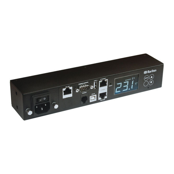
EMX2-111 EMX2-888 All models are functionally identical, but vary in the dimension and total number of ports. Note: For a list of available asset sensor kits and tags, visit the Raritan website's Product Selector page http://www.findmypdu.com/ EMX2-111 EMX2-111 has the following ports and components: ... -
Page 15: Emx2-888
(on page 80), respectively, based on your device type. Package Contents The following describes the equipment shipped with an EMX device. If anything is missing or damaged, contact the local dealer or Raritan Technical Support for help. The EMX device ... -
Page 16: Apipa And Link-Local Addressing
Chapter 1: Introduction APIPA and Link-Local Addressing The EMX supports Automatic Private Internet Protocol Addressing (APIPA). With APIPA, your EMX automatically configures a link-local IP address and a link-local host name when it cannot obtain a valid IP address from any DHCP server in the TCP/IP network. -
Page 17: Before You Begin
Chapter 1: Introduction Retrieval of the link-local IPv4 address: IPv4 Address (on page 75). Before You Begin Prepare the installation site. Make sure the installation area is clean and not exposed to extreme temperatures or humidity. Allow sufficient space around the EMX for cabling and asset strip connections. -
Page 18: Chapter 2 Rack Mounting An Emx
Chapter 2 Rack Mounting an EMX Depending on the model you purchased, the way to mount an EMX device varies. In This Chapter Mounting a Zero U EMX................6 Mounting a 1U EMX ..................7 Mounting a Zero U EMX This section describes how to mount a Zero U EMX device using L-brackets and two buttons. -
Page 19: Mounting A 1U Emx
Chapter 2: Rack Mounting an EMX 4. After both L-brackets are installed, you can choose either of the following ways to mount the device in the rack. Using rack screws, fasten the device to the rack through two identical holes near the edge of each L-bracket. ... - Page 20 Chapter 2: Rack Mounting an EMX 3. Secure with the provided end cap screws. 4. Fasten the rackmount brackets' ears to the rack using your own fasteners.
-
Page 21: Chapter 3 Initial Installation And Configuration
1. Install the cable retention clip by inserting both ends into the tiny holes on two hexagon screws adjacent to the power socket. 2. Plug one end of the Raritan-provided power cord into the power socket, and press the cable retention clip toward the power cord... -
Page 22: Connecting The Emx To Your Network
Chapter 3: Initial Installation and Configuration 3. Connect the other end of the power cord to an appropriate power source. Connecting the EMX to Your Network To remotely administer the EMX, you must connect the EMX to your local area network (LAN). EMX can be connected to a wired or wireless network. -
Page 23: Usb Wireless Lan Adapters
TP-Link TL-WDN3200 v1 A/B/G/N Raritan USB WIFI A/B/G/N Note: To use the Edimax EW-7722UnD or Raritan USB WIFI wireless LAN adapter to connect to an wireless network, the handshake 802.11n timeout setting must be changed to 500 or greater, or the wireless connection will fail. -
Page 24: Connecting The Emx To A Computer
Connecting the EMX to a Computer The EMX can be connected to a computer for configuration via one of the following ports. USB-B port (male) ETHERNET port (female) RS-232 serial port (model dependent -- male DB9 or female RJ-45 connector) EMX2-111:... - Page 25 Initial Network Configuration via CLI (on page 15). Note: Not all serial-to-USB converters work properly with the EMX so Raritan does not introduce the use of such converters. Direct network connection: 1. Connect one end of a standard network patch cable to the ETHERNET port of the EMX.
-
Page 26: Installing The Usb-To-Serial Driver (Optional)
The EMX can emulate a USB-to-serial converter over a USB connection. A USB-to-serial driver named "Dominion EMX Serial Console" is required for Microsoft Windows operating systems. ® ® Download the Windows driver for USB serial console from the Raritan Support page http://www.raritan.com/support/ website's ). The dominion-serial-setup-<n>.exe downloaded driver's name is , where <n>... -
Page 27: Initial Network Configuration Via Cli
3. In the communications program, press Enter to send a carriage return to the EMX. 4. The EMX prompts you to log in. Both user name and password are case sensitive. a. Username: admin b. Password: raritan (or a new password if you have changed it). - Page 28 Chapter 3: Initial Installation and Configuration 5. If prompted to change the default password, change or ignore it. To change it, follow onscreen instructions to type your new password. To ignore it, simply press Enter. 6. The # prompt appears. 7.
- Page 29 Chapter 3: Initial Installation and Configuration Static IP configuration: To set Use this command network <ipvX> interface <ETH> Static IPv4 or address <ip address> IPv6 address <ip address> = static IP address, with a syntax similar to the example below. ...
- Page 30 Chapter 3: Initial Installation and Configuration To set or Use this command enable network wireless enableHT 802.11n <option> protocol true false <option> = , or network wireless authMethod Authentication <method> method <method> = network wireless PSK <psk> <psk> = PSK string network wireless EAP outer eapOuterAuthentication...
- Page 31 Chapter 3: Initial Installation and Configuration The content to be copied from the CA certificate does NOT include the first line containing "BEGIN CERTIFICATE" and the final line containing "END CERTIFICATE." If a certificate is installed, configure the following: Whether to Use this command network wireless Verify the...
-
Page 32: Bulk Configuration Methods
Chapter 3: Initial Installation and Configuration To verify network settings: After exiting the above configuration mode and the # prompt re-appears, type this command to verify all network settings. show network The IP address configured may take seconds to take effect. Bulk Configuration Methods If you have to set up multiple EMX devices, you can use one of the following configuration methods to save your time. -
Page 33: Cascading Multiple Emx Devices For Sharing Ethernet Connectivity
Chapter 3: Initial Installation and Configuration Cascading Multiple EMX Devices for Sharing Ethernet Connectivity You can have multiple EMX devices share one Ethernet connection by cascading them via USB. Warning: To upgrade an existing USB-cascading chain from a version older than 3.3.10, you must start from the last slave device and so on until the master device. -
Page 34: Cascading Guidelines For Port Forwarding
, which is available from Raritan website's page http://www.raritan.com/support/ To cascade EMX devices via USB: 1. Make sure all Raritan devices to be cascaded are running firmware version 3.3.10 or later. 2. Select one as the master device. When the port forwarding mode over wireless LAN is intended, the master device must be a Raritan product with two USB-A ports, such as PX3, EMX2-888, PX3TS or BCM2. - Page 35 Bridging mode: Use a standard network patch cable (CAT5e or higher). Port Forwarding mode: Use a standard network patch cable or a Raritan USB WIFI wireless LAN adapter. For information on the USB Wireless LAN Adapters Raritan USB WIFI adapter, see page 11).
- Page 36 Chapter 3: Initial Installation and Configuration Number Device role Master device Slave 1 Slave 2 8. Configure or change the network settings of the master and/or slave devices as needed. Bridging: Each cascaded device has its own network settings. For example, some devices can have DHCP-assigned IP and the others can have static IP addresses.
-
Page 37: Chapter 4 Connecting External Equipment (Optional)
Chapter 4 Connecting External Equipment (Optional) More features are available if you connect Raritan's or third-party external equipment to your EMX. In This Chapter Connecting Asset Management Strips............25 Connecting Environmental Sensor Packages .......... 39 Connecting a Logitech Webcam..............59 Connecting a GSM Modem ................ -
Page 38: Combining Regular Asset Strips
The difference between the master and slave asset strips is that the master asset strip has an RJ-45 connector while the slave does not. The following diagram illustrates some asset strips. Note that Raritan provides more types of asset strips than the diagram. - Page 39 Chapter 4: Connecting External Equipment (Optional) Make sure that the U-shaped sheet metal adjacent to the male DIN connector is inserted into the rear slot of the master strip. Screw up the U-shaped sheet metal to reinforce the connection. 2.
-
Page 40: Introduction To Asset Tags
Chapter 4: Connecting External Equipment (Optional) Introduction to Asset Tags You need both asset strips and asset tags for tracking IT devices. Asset tags provide an ID number for each IT device. The asset tags are adhered to an IT device at one end and plugged in to an asset strip at the other. -
Page 41: Introduction To Asset Tags
Chapter 4: Connecting External Equipment (Optional) EMX2-111 Connection The FEATURE port of EMX2-111 supports 5 volts of power only, which is insufficient for connecting the latest generation (G3) of asset strips. Therefore, the use of a Raritan X cable is required for EMX2-111 to connect current asset strips, or EMX2-111 cannot detect them. - Page 42 FEATURE port on the EMX2-111 device. MASTER asset strip Asset tags IT devices Raritan X cable Tip: To connect Raritan's environmental sensor packages to EMX2-111, connect them to the female RJ-12 connector of the X cable. For details, (on page 37). Using an X Cable...
-
Page 43: Introduction To Asset Tags
Chapter 4: Connecting External Equipment (Optional) EMX2-888 Connection Unlike EMX2-111, EMX2-888 does NOT need to use a Raritan X cable because its FEATURE port supports 12 volts of power. To connect a regular asset strip assembly to EMX2-888: 1. Assemble regular asset strips according to your needs. See Combining Regular Asset Strips (on page 26). -
Page 44: Connecting Blade Extension Strips
For blade servers, which are contained in a single chassis, you can use a blade extension strip to track individual blade servers. Raritan's blade extension strip functions similar to a Raritan asset strip but requires a tag connector cable for connecting it to a tag port on the regular or composite asset strip. - Page 45 Chapter 4: Connecting External Equipment (Optional) Mylar section with the adhesive tape Tag ports Cable socket(s) for connecting the tag connector cable Note: Each tag port on the blade extension strip is labeled a number, which is displayed as the slot number in the EMX device's web interface. To install a blade extension strip: 1.
- Page 46 Chapter 4: Connecting External Equipment (Optional) a. Affix the adhesive part of the asset tag to one side of a blade server through the tag's tape. b. Plug the tag connector of the asset tag into a tag port on the blade extension strip.
-
Page 47: Connecting Composite Asset Strips (Ams-Mx-Z)
Chapter 4: Connecting External Equipment (Optional) Connecting Composite Asset Strips (AMS-Mx-Z) A composite asset strip is named AMS-Mx-Z, where x is a number, such as AMS-M2-Z or AMS-M3-Z. It is a type of asset strip that functions the same as regular MASTER asset strips except for the following differences: ... - Page 48 The maximum cable length between composite asset strips is 2 meters, but the total cable length cannot exceed 10 meters. The maximum number of composite asset strips that can be daisy chained depend on the Raritan product you purchased. Raritan devices Maximum strips per chain EMX2-111, Up to 4 composite asset strips are supported.
- Page 49 PMC (BCM2 series) Tip: To increase the maximum number of composite asset strips attached to a Raritan PX2 PDU, EMX2-111 or BCM1, use Raritan's X cable to enhance the power supply to the asset strip chain. See Using an X (on page 37).
- Page 50 Chapter 4: Connecting External Equipment (Optional) 2. Plug the male RJ-12 phone connector at the shorter end of the X cable into the RJ-12 SENSOR port on the EMX2-111 device. This step is required for enhancing the power supply to asset strips.
-
Page 51: Connecting Environmental Sensor Packages
Chapter 4: Connecting External Equipment (Optional) 4. Connect any Raritan environmental sensor package or sensor hub to the female RJ-12 sensor port of the X cable if environmental sensor packages are needed. Note that a DX or DPX3 sensor requires an RJ-12 to RJ-45 adapter to connect the X cable. -
Page 52: Dpx Sensor Packages
Chapter 4: Connecting External Equipment (Optional) Model Supported maximum number of sensors/actuators EMX2-111 This model has only one SENSOR port so it can manage up to 32 sensors and/or actuators. EMX2-888 This model has 8 SENSOR ports, which can manage up to 128 sensors and/or actuators in total. - Page 53 EMX. To connect a DPX differential air pressure sensor: 1. Plug one end of a Raritan-provided phone cable into the IN port of a differential air pressure sensor. 2. Plug the other end of this phone cable into the RJ-12 SENSOR port on the EMX.
- Page 54 DPX2, DPX3 or DX sensor packages to it. DPX-ENVHUB4 sensor hubs CANNOT be cascaded. You can connect only one hub to each SENSOR port on the EMX. Tip: The Raritan sensor hub that supports ALL types of Raritan environmental sensor packages is . See...
- Page 55 Chapter 4: Connecting External Equipment (Optional) DPX sensor packages Using an Optional DPX-ENVHUB2 cable A Raritan DPX-ENVHUB2 cable doubles the number of connected environmental sensors per SENSOR port. This cable supports DPX sensor packages only. Do NOT connect DPX2, DPX3 or DX sensor packages to it.
- Page 56 Chapter 4: Connecting External Equipment (Optional) 2. The cable has two RJ-12 sensor ports. Connect DPX sensor packages to the cable's sensor ports. 3. Repeat the above steps if there are additional SENSOR ports on your EMX.
- Page 57 Sensor connection restrictions: Connect a DPX sensor package to the EMX using the sensor cable pre-installed (or provided) by Raritan. You MUST NOT extend or modify the sensor cable's length by using any tool other than the Raritan's sensor hubs.
- Page 58 RJ-12 connector and one to three head connectors. You have to connect DPX2 sensor packages to the sensor cable. For more information on DPX2 sensor packages, access the Environmental Sensors Guide or Online Help on Raritan website's Support page http://www.raritan.com/support/...
- Page 59 Chapter 4: Connecting External Equipment (Optional) The following procedure illustrates a DPX2 sensor cable with three head connectors. Your sensor cable may have fewer head connectors. Warning: If there are free head connectors between a DPX2 sensor cable's RJ-12 connector and the final attached DPX2 sensor package, the sensor packages following the free head connector(s) on the same cable do NOT work properly.
- Page 60 Chapter 4: Connecting External Equipment (Optional) 3. Plug the RJ-12 connector of the DPX2 sensor cable into the RJ-12 SENSOR port on the EMX. OR you can directly connect the DPX2 sensor package to a DX sensor Connecting a chain without using any RJ-12 to RJ-45 adapter. See DPX2 Sensor Package to DX (on page 52).
- Page 61 Chapter 4: Connecting External Equipment (Optional) To connect DPX3 sensor packages to the EMX: 1. Connect an RJ-12 to RJ-45 adapter cable to the DPX3 sensor package. Connect the adapter's RJ-45 connector to either RJ-45 port of the DPX3 sensor package. 2.
- Page 62 Chapter 4: Connecting External Equipment (Optional) Connecting a DPX2 Sensor Package to DPX3 You can connect only one DPX2 sensor package to the "end" of a DPX3 sensor chain. It is strongly recommended to use an RJ-12 to RJ-45 adapter for connecting the DPX2 to the final DPX3 in the chain. The maximum number of DPX3 sensor packages in the chain must be less than 12 when a DPX2 sensor package is involved.
- Page 63 Most DX sensor packages contain terminals for connecting detectors or actuators. For information on connecting actuators or detectors to DX terminals, refer to the Environmental Sensors Guide or Online Help on Raritan website's Support page http://www.raritan.com/support/ You can cascade up to 12 DX sensor packages.
- Page 64 Chapter 4: Connecting External Equipment (Optional) a. Plug one end of the cable into the remaining RJ-45 port on the prior DX package. b. Plug the other end into either RJ-45 port on an additional DX package. Repeat the same steps to cascade more DX packages. 3.
-
Page 65: Using An Optional Dpx3-Envhub4 Sensor Hub
A maximum of eleven DX sensor packages can be cascaded because 12-1=11. Using an Optional DPX3-ENVHUB4 Sensor Hub A Raritan DPX3-ENVHUB4 sensor hub is physically and functionally similar to the DPX-ENVHUB4 sensor hub, which increases the number of sensor ports for the EMX, except for the following differences: ... - Page 66 Chapter 4: Connecting External Equipment (Optional) 2. Connect the Raritan sensor packages to any of the four OUT ports on the hub. An RJ-12 to RJ-45 adapter is required for connecting a DPX or DPX2 sensor package to the hub.
-
Page 67: Mixing Diverse Sensor Types
Chapter 4: Connecting External Equipment (Optional) Mixing Diverse Sensor Types You can mix DPX, DPX2, DPX3 and DX sensor packages on any sensor port of the EMX2-888 or EMX2-111 according to the following sensor combinations. In some scenarios, the DPX3-ENVHUB4 sensor hub is required. - Page 68 Chapter 4: Connecting External Equipment (Optional) An RJ-12 to RJ-45 adapter is recommended to connect a DPX or DPX2 sensor package to DPX3-ENVHUB4. In the following diagrams, the sensor package in "green" can be replaced by a DPX2 sensor package. The sensor package in "blue" can be one DPX2, DPX3 or DX sensor package.
- Page 69 Chapter 4: Connecting External Equipment (Optional)
- Page 70 Chapter 4: Connecting External Equipment (Optional) Mix DPX3 and DX in a sensor chain: Any DX sensor package in a chain can be replaced by a DPX3 sensor package, or vice versa. The total number of sensor packages in this chain cannot exceed 12.
-
Page 71: Connecting A Logitech Webcam
Pro 9000, Model 960-000048 ® ® Other UVC-compliant webcams may also work. However, Raritan has neither tested them nor claimed that they will work properly. Tip: You can easily find a list of UVC-compliant webcams on the Internet. The EMX supports up to two webcams. You can use a "powered" USB hub to connect webcams if needed. -
Page 72: Connecting A Gsm Modem
NETCOMM IG6000 Industrial Grade SmartModem US Robotics 56K modem The EMX may also support other analog modems which Raritan did not test. Note that the EMX does NOT support dial-out or dial-back operations via the modem. To connect an analog modem: 1. -
Page 73: Connecting An External Beeper
Chapter 4: Connecting External Equipment (Optional) You need to enable the modem dial-in support to take advantage of this Configuring the Serial Port feature, see (on page 253). Connecting an External Beeper The EMX supports the use of an external beeper for audio alarms. External beepers that are supported include but may not be limited to the following: ... - Page 74 Chapter 4: Connecting External Equipment (Optional) To connect an SHX-30 heat exchanger: 1. Plug one end of the Schroff adapter cable into the RS-485 port on the Schroff SHX heat exchanger. 2. Plug the other end of the adapter cable into one of available RS-485 ports on your EMX.
-
Page 75: Connecting The Schneider Electric Powerlogic Pm710
PM710 is viewed in the EMX web interface. This device is only supported when plugged into the RS485 port using a PM710 supported cable (not provided by Raritan with the EMX). A maximum of one PM710 can be connected to each RS485 port. You cannot daisy chain PM710 units because the EMX does not support a PM710 daisy chain. - Page 76 Chapter 4: Connecting External Equipment (Optional) b. Connect an RS232-to-USB adapter (using FTDI's FT232 chip) to the RS485-to-RS232 adapter. c. Connect the RS232-to-USB adapter to the USB-A port on the EMX. Note: DO NOT connect the Modbus RTU device or Modbus bus to the RS485 ports on the EMX, which is NOT supported.
-
Page 77: Chapter 5 Using The Emx
Beeper ....................... 85 Power Switch A power switch turns on or off the EMX. EMX2-111 front panel power switch: EMX2-888 rear panel power switch: To power cycle the EMX, turn off the device, wait at least 10 seconds and turn it back on. - Page 78 Chapter 5: Using the EMX EMX2-888...
-
Page 79: Cascading The Emx Via Usb
Connection to one of the following devices: Raritan's environmental sensor package(s). Raritan's sensor hub, which expands the number of a sensor port to four ports. RS-485 Connection to an electrical device with the RS-485 interface. Currently the EMX supports the Schroff LHX-20, LHX-40 and SHX-30 ®... -
Page 80: Lcd Display Panel
Establishing a USB connection between a computer and the EMX for using the command line interface or performing the disaster recovery. For disaster recovery instructions, contact Raritan Technical Support. LCD Display Panel The LCD display panel shows the sensor reading or status, asset management states and the device's IP or MAC address. -
Page 81: Overview Of The Lcd Display
A discrete (on/off) sensor enters the alarmed state. NO asset tag is detected on the selected rack unit. Note: For the Raritan asset sensor, a rack unit refers to a tag port. The measurement unit of the displayed data, such as % This section indicates: ... -
Page 82: Control Buttons
Chapter 5: Using the EMX Control Buttons There are four control buttons. Up and Down buttons for selecting a specific target, which can be an environmental sensor's ID number or an asset sensor's port number MODE button for switching between various modes, including: - Sensor mode - Asset Sensor mode, indicated by the word ASSET, for showing the asset sensor information... - Page 83 Chapter 5: Using the EMX Number Example information The selected target is the environmental sensor whose ID number is 9 (SENSOR 9). The selected environmental sensor's reading is 22 The word "MASTER" indicates the EMX is the master device in a cascading configuration. For a slave device, it shows "SLAVE"...
- Page 84 Chapter 5: Using the EMX States Description Normal state. Alarmed state. This state is accompanied with the word "ALARM" below it. Available states for a dry contact signal actuator (DX sensor series): States Description The actuator is turned on. The actuator is turned off.
- Page 85 Asset Sensor Information The LCD display can show the asset sensor state on each FEATURE port as well as the asset tag state of each rack unit. For the Raritan asset sensor, a rack unit refers to a tag port.
- Page 86 Chapter 5: Using the EMX Section Example information The word "MASTER" indicates the EMX is the master device in a cascading configuration. For a slave device, it shows "SLAVE" instead. Note: As of release 3.3.10, the "MASTER/SLAVE" information is no longer available in the bridging mode, but remains available in the port forwarding mode.
- Page 87 Chapter 5: Using the EMX IPv4 Address The IP address is available in the Device mode, which is indicated by the alphabet 'd' shown at the top of the LCD display. Note that the LCD display only shows the IPv4 address (if available). Below illustrates the IP address information.
- Page 88 Chapter 5: Using the EMX To display the IPv4 address: 1. Press the MODE button to enter the Device mode, indicated by an alphabet "d" at the top left of the display. 2. The LCD display cycles between the four octets of the IPv4 address, indicated by "i4"...
-
Page 89: Usb-Cascaded Device's Position
Chapter 5: Using the EMX 3. The MAC address is displayed as "M:XX", where XX are two digits of the MAC address. The LCD will cycle through the MAC address from the first two digits to the final two. For example, if the MAC address is 00:0d:5d:03:5E:1A, the LCD display shows the following information one after another: M 00 -->... - Page 90 Chapter 5: Using the EMX 2. Press the FUNC button until "CA" is displayed at the top right of the display. 3. The device's position is represented by any number defined below: Number Device position Master device Slave 1 Slave 2 Slave 3 Slave 4 Slave 5...
-
Page 91: Emx2-888 Contact Closure Sensor Termination
Chapter 5: Using the EMX EMX2-888 Contact Closure Sensor Termination An EMX2-888 model contains two built-in contact closure (CC) sensor channels, each of which comprises two termination points. EMX2-888 is designed to use a detachable terminal module for CC sensor termination, which makes installation of contact closure sensors more convenient. -
Page 92: Connecting Contact Closure Sensors To Emx2-888
To set to Normally Open (N.O), press the button to turn it up. Tip: Alternatively, third-party CC switches can be connected to Raritan's DPX-CC2-TR or DX sensor package, which is then connected to a SENSOR port on the EMX. For sensor information, refer to the... - Page 93 Chapter 5: Using the EMX The two termination points to the right are associated with channel 1 (CC1 as indicated in the panel), and the two to the left are associated with channel 2 (CC2). With this design, there are two ways to plug discrete detectors/switches: ...
- Page 94 Chapter 5: Using the EMX 3. Use a screwdriver with a 2.5 mm wide shaft to tighten the screws above each termination point to secure the wires, using a torque of 0.196 N·m (2 kgf·cm). To make connections when the terminal module is separated from the EMX: 1.
- Page 95 Chapter 5: Using the EMX 3. Strip the insulation and insert each wire of both detectors/switches into each termination point. 4. Use a screwdriver with a 2.5 mm wide shaft to tighten the screws above each termination point to secure the wires, using a torque of 0.196 N·m (2 kgf·cm).
-
Page 96: Emx2-888 Contact Closure Sensor Leds
Chapter 5: Using the EMX 6. Tighten the two screws on two sides of the module to secure it. EMX2-888 Contact Closure Sensor LEDs Two LEDs that show the states of corresponding CC sensor channels are located on the leftmost of the EMX2-888 panel. ... -
Page 97: Reset Button
Chapter 5: Using the EMX For Raritan's DPX water sensors, the Normal state must be set to Normally Open (N.O). The following is the correct LED behavior based on proper dip switch settings. Sensor state No water detected Water detected Reset Button The reset button is located inside a small hole which is labeled RESET. -
Page 98: Chapter 6 Using The Web Interface
Chapter 6 Using the Web Interface This chapter explains how to use the web interface to administer a EMX. In This Chapter Supported Web Browsers ................. 86 Login, Logout and Password Change ............86 Web Interface Overview................89 Dashboard ....................94 EMX ...................... -
Page 99: Login
Chapter 6: Using the Web Interface Login You must enable JavaScript in the web browser for proper operation. To log in to the web interface: 1. Open a browser and type the IP address of the EMX. If the link-local addressing has been enabled, you can type pdu.local APIPA and Link-Local instead of an IP address. -
Page 100: Changing Your Password
Chapter 6: Using the Web Interface Note: The address to access a slave device in the port forwarding mode via non-standard ports is a combination of a protocol (http:// or https://), an IP address and a port number. See Port Forwarding Examples page 166). -
Page 101: Remembering User Names And Passwords
Chapter 6: Using the Web Interface Remembering User Names and Passwords The EMX supports the password manager of common web browsers, including: Microsoft Internet Explorer ® Mozilla Firefox ® Google Chrome ® You can save the login name and password when these browsers ask whether to remember them. -
Page 102: Menu
Chapter 6: Using the Web Interface 4. To return to the main menu and the Dashboard page, click on the top-left corner. Number Web interface element Menu (on page 91) Data/setup page of the selected menu item Left side: - EMX device name Note: To customize the device name, see (on page 98). - Page 103 - See Browsing through the Online Help (on page 540). Raritan Support: link to the Raritan Technical Support webpage. Date and time of your user account's last login - Click Last Login to view your login history. EMX system time - Click Device Time to open the Date/Time setup page.
-
Page 104: Dashboard
(on page 94). Device data and settings, such as the device name and MAC address. (on page 98). Peripherals Status and settings of Raritan environmental sensor packages, if connected. Peripherals (on page 101). Feature Port(s) Status and settings of the device connected to the Feature port(s), which can be one of the following. -
Page 105: Quick Access To A Specific Page
Chapter 6: Using the Web Interface Menu Information shown Maintenance Device information and maintenance commands, such as firmware upgrade, device backup and reset. Maintenance (on page 260). If a menu item contains the submenu, the submenu is shown after clicking that item. To return to the previous menu list, do any below: ... -
Page 106: Sorting A List
Chapter 6: Using the Web Interface Sorting a List If any list displays this arrow in one of its column headers, you are allowed to resort the list by clicking any column header. The list will be resorted in the ascending or descending order based on the selected column. -
Page 107: Dashboard - Alerted Sensors
Chapter 6: Using the Web Interface Number Section Information shown When no sensors enter the alarmed state, this section shows Alerted the message "No Alerted Sensors." Sensors When any sensor enters the alarmed state, this section lists all of them. - Page 108 Chapter 6: Using the Web Interface - State sensors enter the alarmed state. 1 Warned: 1 'numeric' sensor enters the warning state. List of alerted sensors: Two icons are used to indicate various sensor states. Icons Sensor states For numeric sensors: ...
-
Page 109: Dashboard - Alarms
Chapter 6: Using the Web Interface Dashboard - Alarms If configuring any event rules which require users to take the acknowledgment action, the Alarms section will list any event which no one acknowledges yet since event occurrence. Note: For information on event rules, see Event Rules and Actions page 204). -
Page 110: Emx
Chapter 6: Using the Web Interface Field Description More Alerts This field appears only when there are more than one type of events triggering this alert. If there are other types of events (that is, other reasons) triggering the same alert, the total number of additional reasons is displayed. - Page 111 The default is to enable it. The device's altitude is associated Altitude Specifies the EMX device's altitude with the altitude correction factor. above sea level when a Raritan's DPX Altitude Correction Factors differential air pressure sensor is (on page 532). attached.
-
Page 112: Z Coordinate Format
EMX automatically brings newly-connected environmental sensors and actuators under management after detecting them. EMX2-111 can manage up to 32 sensors/actuators per unit. EMX2-888 can manage up to 32 sensors/actuators per sensor port, but the total CANNOT exceed 130 per unit. -
Page 113: Peripherals
Peripherals You must manually manage new sensors/actuators. See page 101). Peripherals If there are Raritan environmental sensor packages connected to the Connecting EMX, they are listed on the Peripherals page. See Environmental Sensor Packages (on page 39). An environmental sensor package comprises one or some of the following sensors/actuators: ... - Page 114 Chapter 6: Using the Web Interface Note: To disable the automatic management function, go to page 98). You need to manually manage a sensor/actuator only when it is not under management. When any sensor/actuator is no longer needed, you can unmanage/release it.
- Page 115 Sensor/Actuator States (on page 108). Type Sensor or actuator type. Serial Number This is the serial number printed on the sensor package's label. It helps to identify your Raritan sensors/actuators. See Finding the Sensor's Serial Number (on page 110). Position The data indicates where this sensor or actuator is located in the sensor chain.
- Page 116 Chapter 6: Using the Web Interface To release or manage sensors/actuators: When the total of managed sensors/actuators reaches the maximum (32), you cannot manage additional ones. The only way to manage any sensor/actuator is to release or replace any managed ones. To replace a managed sensor/actuator, see Managing One Sensor or Actuator page 112).
- Page 117 Chapter 6: Using the Web Interface Managed ones show one of the managed states. To configure default threshold settings: Note that any changes made to default threshold settings not only re-determine the initial threshold values applying to newly-added sensors but also the threshold values of the already-managed sensors where default thresholds are being used.
-
Page 118: Yellow- Or Red-Highlighted Sensors
Chapter 6: Using the Web Interface : Turn ON. : Turn OFF. 3. Confirm the operation when prompted. Yellow- or Red-Highlighted Sensors The EMX highlights those sensors that enter the abnormal state with a yellow or red color. Note that numeric sensors can change colors only after you have enabled their thresholds. -
Page 119: Managed Vs Unmanaged Sensors/Actuators
Chapter 6: Using the Web Interface Sensor status Color States shown in Description the interface Critical above upper Upper Critical threshold < "R" critical below lower "R" < Lower Critical threshold critical alarmed State sensors enter the abnormal state. Alarmed If you have connected a Schroff LHX/SHX heat exchanger, when any ®... -
Page 120: Sensor/Actuator States
Chapter 6: Using the Web Interface Sensor/Actuator States They show one of the managed states. See (on page 108). For managed 'numeric' sensors, their readings are retrieved and displayed. If any numeric sensor is disconnected or its reading cannot be retrieved, it shows "unavailable"... - Page 121 Note that for a contact closure sensor, the normal state depends on the normal setting you have configured. Refer to the Environmental Sensors Guide or Online Help for detailed information, which is available on Support page http://www.raritan.com/support/ Raritan's Managed actuator states: State Description The actuator is turned on.
-
Page 122: Finding The Sensor's Serial Number
Chapter 6: Using the Web Interface Finding the Sensor's Serial Number A DPX environmental sensor package includes a serial number tag on the sensor cable. A DPX2, DPX3 or DX sensor package has a serial number tag attached to its rear side. The serial number for each sensor or actuator appears listed in the web interface after each sensor or actuator is detected by the EMX. -
Page 123: Identifying The Sensor Position And Channel
For example, Port 1, Chain Position 2 If a Raritan DPX3-ENVHUB4 sensor hub is involved, the hub port information is also indicated for DPX2, DPX3 and DX series, but NOT indicated for DPX series. For example, Hub Port 3 ... -
Page 124: Managing One Sensor Or Actuator
Chapter 6: Using the Web Interface Example Physical position Connected to the sensor port #1. Port 1 Connected to the sensor port #1. Port 1, The sensor/actuator is the 2nd channel of the sensor package. Channel 2 Connected to the sensor port #1. Port 1, ... - Page 125 Otherwise, it shows the word "unused." 3. Click Manage. Special note for a Raritan humidity sensor: A Raritan humidity sensor is able to provide two measurements - relative and absolute humidity values. A relative humidity value is measured in percentage (%).
-
Page 126: Individual Sensor/Actuator Pages
Chapter 6: Using the Web Interface However, only relative humidity sensors are "automatically" managed if the automatic management function is enabled. You must "manually" manage absolute humidity sensors as needed. Note that relative and absolute values of the same humidity sensor do NOT share the same ID number though they share the same serial number and position. - Page 127 Chapter 6: Using the Web Interface 2. Select or deselect Use Default Thresholds according to your needs. To have this sensor follow the default threshold settings configured for its sensor type, select the Use Default Thresholds checkbox. The default threshold settings are configured on the page of Peripherals (on page 101).
- Page 128 Chapter 6: Using the Web Interface To set up a sensor's or actuator's physical location and additional settings: 1. Click Edit Settings. 2. Make changes to available fields, and then click Save. Fields Description Binary Sensor This field is available for a contact closure sensor only. Subtype Determine the sensor type of your contact closure detector.
- Page 129 Chapter 6: Using the Web Interface To view a numeric sensor's readings waveform: This sensor's data within the past tens of minutes is shown in the waveform diagram. Note that only a numeric sensor has this diagram. State sensors and actuators do not show such data. To turn on or off an actuator: 1.
-
Page 130: Sensor/Actuator Location Example
Chapter 6: Using the Web Interface 2. Confirm the operation on the confirmation message. An actuator's state is marked in red when it is turned on. Other operations: You can go to another sensor's or actuators's data/setup page by clicking the selector on the top-left corner. -
Page 131: Feature Port(S)
LHX/SHX heat exchanger. See ® (on page 260). Miscellaneous EMX2-111 Feature Port mode configuration: When the EMX detects the connection of any listed device, it replaces 'Feature Port' in the menu with that device's name and shows that device's data/settings instead. -
Page 132: Asset Strip
Disabled Disable the port's detection capability. Asset Strip, Force the EMX to show the selected device's data/setup page regardless of the physical Raritan asset connection status. strips, LHX 20, SHX 30, LHX 40 Note: 'LHX 20', 'SHX 30', and 'LHX 40' are not available when the support of LHX/SHX heat exchangers is disabled. - Page 133 EMX2-888 shows 'Asset Strip' for those ports where asset strips are physically connected on the Feature Ports page. EMX2-111 shows 'Asset Strip' in place of 'Feature Port' in the Menu (on page 91). Note: For connection instructions, see Connecting Asset Management (on page 25).
- Page 134 Chapter 6: Using the Web Interface Field Description Number of Rack Total of available tag ports on this asset strip Units assembly, ranging between 8 and 64. For the current generation of asset strips, which show the suffix "G3" on its hardware label, the EMX automatically detects the number of its tag ports (rack units), and you cannot...
- Page 135 Chapter 6: Using the Web Interface Click a color in the color palette. Type the hexadecimal RGB value of the color, such as #00FF00. 3. Click Ok. The rack unit numbering and LED color settings are immediately updated on the Rack Units list illustrated below. ...
- Page 136 Chapter 6: Using the Web Interface To customize a single rack unit's settings: You can make a specific rack unit's LED behave differently from the others on the asset strip, including the LED light and color. 1. Click the desired rack unit on the Rack Units list. The setup dialog for the selected one appears.
- Page 137 Chapter 6: Using the Web Interface Field Description LED Mode This field is configurable only after the Operation Mode is set to Manual Override. Determine how the LED light behaves for this particular rack unit. : The LED stays lit. ...
- Page 138 Chapter 6: Using the Web Interface 2. All tag ports of the blade extension strip are listed below it. Their port numbers are displayed in the Slot column. To hide the blade extension slots list, click...
- Page 139 Chapter 6: Using the Web Interface To customize asset IDs on programmable asset tags: You can customize asset IDs only when the asset tags are "programmable" ones. Non-programmable tags do not support this feature. In addition, you can also customize the ID of a blade extension strip.
- Page 140 Chapter 6: Using the Web Interface An asset ID contains up to 12 characters that comprise only numbers and/or UPPER CASE alphabets. Lower case alphabets are NOT accepted. 3. Verify the correctness of customized asset IDs and modify as needed.
-
Page 141: External Beeper
EMX2-888 shows 'External Beeper' for those ports where external beepers are physically connected on the Feature Ports page. EMX2-111 shows 'External Beeper' in place of 'Feature Port' in Menu (on page 91). Note: For connection instructions, see Connecting an External Beeper (on page 61). -
Page 142: Schroff Lhx/Shx
EMX2-888 shows the LHX or SHX name for those ports where LHX/SHX heat exchangers are physically connected on the Feature Ports page. EMX2-111 shows the LHX or SHX name in place of 'Feature Port' Menu in the (on page 91). - Page 143 Chapter 6: Using the Web Interface Feature Port(s) For the Feature Port's mode configuration, see (on page 119). To view the LHX/SHX device state: The Operation State field indicates whether the device is operating fine, and the Switch State field indicates its power status. If the device does not operate properly, such as some sensor failure, it shows "critical"...
- Page 144 Chapter 6: Using the Web Interface Tip: You can also create event rules to notify you of the warning or critical levels. See (on page 204). Event Rules and Actions To view sensor alerts and LHX event log: Remote alert acknowledgment is supported by the LHX-20 and LHX-40. The SHX-30 does not support this feature.
-
Page 145: Auxiliary Port(S)
(on page 260). Miscellaneous EMX2-111 Auxiliary Port mode configuration: When EMX2-111 detects the connection of any listed device, it replaces 'Auxiliary Port' in the menu with that device's name and shows that device's data/settings instead. When no devices are detected, EMX2-111 displays the name 'Auxiliary Port"... - Page 146 Chapter 6: Using the Web Interface Mode Description Auto Enable the port to automatically detect the device connection. Disabled Disable the port's detection capability. LHX 20, Force the EMX to show the selected device's data/setup page regardless of the physical SHX 30, connection status.
-
Page 147: Schneider Electric Powerlogic Pm710
Chapter 6: Using the Web Interface Schneider Electric PowerLogic PM710 All settings are configured on a per port basis. If you disconnect a PM710 from one EMX port and connect it to another EMX port, you must reconfigure the settings. However, if you disconnect a PM710 from an EMX port and then plug it back into the same port, the already-configured settings still apply. - Page 148 Chapter 6: Using the Web Interface To configure threshold settings for PM710: 1. Click the Thresholds title bar at the bottom of the page to display a list of sensor thresholds. 2. Click the desired sensor (required), and then click Edit Thresholds. 3.
- Page 149 Chapter 6: Using the Web Interface Type a new value in the accompanying text box. For concepts of thresholds, deassertion hysteresis and assertion Sensor Threshold Settings timeout, see (on page 523). 4. Click Save. To reset the PM710 minimum and maximum values: 1.
-
Page 150: User Management
Chapter 6: Using the Web Interface User Management User Management menu deals with user accounts, permissions, and preferred measurement units on a per-user basis. The EMX is shipped with one built-in administrator account: admin, which is ideal for initial login and system administrator. You can neither delete 'admin' nor change its permissions. - Page 151 Chapter 6: Using the Web Interface User information: Field/setting Description User Name The name the user enters to log in to the EMX. 4 to 32 characters Case sensitive Spaces are NOT permitted. Full Name The user's first and last names. ...
- Page 152 Chapter 6: Using the Web Interface Field/setting Description (on page 172). Security Level Click the field to select a preferred security level from the list: None: No authentication and no privacy. This is the default. Authentication: Authentication and no privacy. ...
- Page 153 Chapter 6: Using the Web Interface Protocol: This section is configurable only when 'Authentication' or 'Authentication & Privacy' is selected. Field/setting Description Authentication Click this field to select the desired authentication protocol. Two protocols are available: SHA-1 (default) Privacy Click this field to select the desired privacy protocol.
-
Page 154: Editing Or Deleting Users
Chapter 6: Using the Web Interface Note: Users can change the measurement units at any time by setting their own preferences. See Setting Your Preferred Measurement Units (on page 146). Roles: Select one or multiple roles to determine the user's permissions. To select all roles, select the top-most checkbox in the header row. -
Page 155: Creating Roles
Chapter 6: Using the Web Interface To change the password, type a new password in the Password and Confirm Password fields. If the password field is left blank, the password remains unchanged. To delete this user, click , and confirm the operation. 3. - Page 156 Chapter 6: Using the Web Interface If the two do not satisfy your needs, add new roles. To create a role: 1. Choose User Management > Roles > 2. Assign a role name. 1 to 32 characters long Case sensitive ...
-
Page 157: Editing Or Deleting Roles
Chapter 6: Using the Web Interface Editing or Deleting Roles Choose User Management > Roles to open the Roles page, which lists all roles. If wanted, you can resort the list by clicking the desired column header. Sorting a List (on page 94). -
Page 158: Setting Your Preferred Measurement Units
Chapter 6: Using the Web Interface Setting Your Preferred Measurement Units You can change the measurement units shown in the EMX user interface according to your own preferences regardless of the permissions you have. Tip: Preferences can also be changed by administrators for specific users on the Edit User page. - Page 159 Chapter 6: Using the Web Interface Setting Default Measurement Units Default measurement units are applied to all EMX user interfaces across all users, including users accessing the EMX via external authentication servers. For a list of affected user interfaces, see User Interfaces Showing Default Units (on page 147).
-
Page 160: Device Settings
Chapter 6: Using the Web Interface Device Settings Menu Click 'Device Settings' in the (on page 91), and the following submenu displays. Menu command Submenu command Refer to... Network Configuring Network Settings (on page 149) Changing HTTP(S) Settings Network Services HTTP (on page 171) Configuring SNMP Settings... - Page 161 Chapter 6: Using the Web Interface Configuring Network Settings Configure wired, wireless, and Internet protocol-related settings on the Network page after connecting the EMX to your network (on page 10). You can enable both the wired and wireless networking on the EMX so that it has multiple IP addresses -- wired and wireless IP.
- Page 162 Chapter 6: Using the Web Interface Ethernet 5. To configure the ETHERNET interface settings, see Interface Settings (on page 152). 6. Click Save. After enabling either or both Internet protocols: After enabling IPv4 and/or IPv6, all but not limited to the following protocols will be compliant with the selected Internet protocol(s): ...
- Page 163 Chapter 6: Using the Web Interface Field/setting Description Static: Manually configure the IPv4 settings. DHCP settings: Optionally specify the preferred hostname, which must meet the following requirements: Consists of alphanumeric characters and/or hyphens Cannot begin or end with a hyphen ...
- Page 164 Chapter 6: Using the Web Interface Field Description DNS Resolver Determine which IP address is used when the Reference DNS resolver returns both IPv4 and IPv6 addresses. IPv4 Address: Use the IPv4 addresses. IPv6 Address: Use the IPv6 addresses. DNS Suffixes Specify a DNS suffix name if needed.
- Page 165 Chapter 6: Using the Web Interface Field Description Auto: System determines the optimum LAN speed through auto-negotiation. 10 MBit/s: Speed is always 10 Mbps. 100 MBit/s: Speed is always 100 Mbps. Duplex Select a duplex mode. Auto: The EMX selects the optimum transmission mode through auto-negotiation.
- Page 166 Chapter 6: Using the Web Interface Field/setting Description BSSID Type the MAC address of an access point Enable High Enable or disable 802.11n protocol. Throughput (802.11n) Authentication Select an authentication method. No Authentication: No authentication data is required. PSK: A Pre-Shared Key is required. ...
- Page 167 Chapter 6: Using the Web Interface Field/setting Description Click this button to install a certificate file. Then you can: Click Show to view the certificate's content. Click Remove to delete the installed certificate if it is inappropriate. Select this checkbox to make the Allow expired and authentication succeed regardless of the not yet valid...
- Page 168 Chapter 6: Using the Web Interface Static settings: Assign a static IPv4 address, which follows this syntax "IP address/prefix length". 192.168.84.99/24 Example: IPv6 settings: Field/setting Description Enable IPv6 Enable or disable the IPv6 protocol. IP Auto Select the method to configure IPv6 settings. Configuration ...
- Page 169 Chapter 6: Using the Web Interface If there are more than 5 pages and the page numbers displayed in the bar does not show the desired one, click to have it show the next or previous five page numbers, if available. 3.
- Page 170 Chapter 6: Using the Web Interface Static Route Examples This section describes two static route examples: IPv4 and IPv6. Both examples assume that two network interface controllers (NIC) have been installed in one network server, leading to two available subnets, and IP forwarding has been enabled.
- Page 171 Chapter 6: Using the Web Interface In this example, NIC-2 (192.168.100.88) is the next hop router for your EMX to communicate with any device in the other subnet 192.168.200.0. In the IPv4 "Static Routes" section, you should specify:...
- Page 172 Chapter 6: Using the Web Interface Tip: If you have configured multiple static routes, you can click on any route and then make changes, use to re-sort the priority, or click to delete it. IPv6 example: fd07:2fa:6cff:2405::30 Your EMX: ...
- Page 173 Chapter 6: Using the Web Interface In this example, NIC-2 (fd07:2fa:6cff:2405::80) is the next hop router for your EMX to communicate with any device in the other subnet fd07:2fa:6cff:1111::0. In the IPv6 "Static Routes" section, you should specify: Tip: If you have configured multiple static routes, you can click on any route and then make changes, use to re-sort the priority, or click...
- Page 174 Chapter 6: Using the Web Interface Setting the Cascading Mode A maximum of 16 EMX devices can be cascaded to share one Ethernet connection. See Cascading Multiple EMX Devices for Sharing Ethernet Connectivity (on page 21). The cascading mode configured on the master device determines the Ethernet sharing method, which is either network bridging or port Overview of the Cascading Modes forwarding.
- Page 175 (on page 153). Online USB-cascading information: For more information on the USB-cascading configuration, see the Cascading Guide , which is available from Raritan website's Support page http://www.raritan.com/support/ Overview of the Cascading Modes You must apply a cascading mode to the cascading configuration. See Setting the Cascading Mode (on page 162).
- Page 176 Chapter 6: Using the Web Interface "Bridging" mode: In this mode, the DHCP server communicates with every cascaded different device respectively and assigns four IP addresses. Each device has its own IP address. The way to remotely access each cascaded device is completely the same as accessing a standalone device in the network.
- Page 177 Chapter 6: Using the Web Interface Port Number Syntax In the Port Forwarding mode, all devices in the USB-cascading configuration share the same IP address. To access any cascaded device, you must assign an appropriate port number to it. 5NNXX Master device: The port number is either or the standard...
- Page 178 Slave device: Assign proper 5NNXX port numbers. The Port Forwarding mode is applied to a USB-cascading Assumption: configuration comprising three Raritan devices. The IP address is 192.168.84.77. Master device: Position code for the master device is '00' so each port number is 5NN00 as listed below.
- Page 179 Chapter 6: Using the Web Interface Protocols Port numbers HTTP 50100 50200 TELNET 50300 SNMP 50500 MODBUS 50600 Examples using "5NN00" ports: To access the master device via HTTPS, the IP address is: https://192.168.84.77:50000/ To access the master device via HTTP, the IP address is: http://192.168.84.77:50100/ ...
- Page 180 Chapter 6: Using the Web Interface Examples: To access Slave 1 via HTTPS, the IP address is: https://192.168.84.77:50001/ To access Slave 1 via HTTP, the IP address is: http://192.168.84.77:50101/ To access Slave 1 via SSH, the command is: ssh -p 50201 192.168.84.77 Slave 2 device: Position code for Slave 2 is '02' so each port number is 5NN02 as shown...
- Page 181 Chapter 6: Using the Web Interface Adding, Removing or Swapping Cascaded Devices Change the cascading mode first before adding any device to a cascading chain, or before disconnecting a cascaded device from the chain. If you only want to change the cascading mode of an existing chain, or swap the master and slave device, always start from the slave device.
-
Page 182: Configuring Network Services
Enabling Service Advertising Service Advertising (on page 178) Important: Raritan uses TLS instead of SSL 3.0 due to published security vulnerabilities in SSL 3.0. Make sure your network infrastructure, such as LDAP and mail services, uses TLS rather than SSL 3.0. - Page 183 Chapter 6: Using the Web Interface Changing HTTP(S) Settings HTTPS uses Transport Layer Security (TLS) technology to encrypt all traffic to and from the EMX so it is a more secure protocol than HTTP. The EMX supports TLS By default, any access to the EMX via HTTP is automatically redirected to HTTPS.
- Page 184 Chapter 6: Using the Web Interface Configuring SNMP Settings You can enable or disable SNMP communication between an SNMP manager and the EMX device. Enabling SNMP communication allows the manager to retrieve and even control the power status of each outlet. Besides, you may need to configure the SNMP destination(s) if the built-in "System SNMP Notification Rule"...
- Page 185 Chapter 6: Using the Web Interface a. Click the Download MIBs title bar to show the download links. Downloading SNMP MIB b. Click the EMD-MIB download link. See (on page 287). 6. Click Save. Configuring SMTP Settings The EMX can be configured to send alerts or event messages to a specific administrator by email.
- Page 186 Chapter 6: Using the Web Interface Field Description User Name, Type a user name and password for authentication after selecting the above checkbox. Password The length of user name and password ranges between 4 and 64. Case sensitive. Spaces are not allowed for the user name, but allowed for the password.
- Page 187 Chapter 6: Using the Web Interface Special note for AES ciphers: The EMX device's SSL/TLS-based protocols, including SMTP over StartTLS, support AES 128- and 256-bit ciphers. The exact cipher to use is negotiated between the EMX and the client (such as a web browser), which is impacted by the cipher priority of the EMX and the client's cipher availability/settings.
- Page 188 Chapter 6: Using the Web Interface 3. To use a different port, type a new port number. 4. Click Save. Changing Modbus Settings The EMX supports both the Modbus/TCP and Modbus Gateway features. Enable either or both Modbus features according to your needs. Modbus/TCP Access: You can enable or disable the Modbus/TCP access to the EMX, set it to the read-only mode, or change the TCP port.
- Page 189 Chapter 6: Using the Web Interface Field Description Use the default port 503, or assign a different port. Valid TCP Port range is 1 to 65535. Note: Port 502 is the default Modbus/TCP port for EMX, so you cannot use that port for the Modbus Gateway. Use the default values, or update if the Modbus RTU devices Parity, are using different communication parameters.
- Page 190 Chapter 6: Using the Web Interface Enabling Service Advertising The EMX advertises all enabled services that are reachable using the IP network. This feature uses DNS-SD (Domain Name System-Service Discovery) and MDNS (Multicast DNS). The advertised services are discovered by clients that have implemented DNS-SD and MDNS. The advertised services include the following: ...
-
Page 191: Configuring Security Settings
Chapter 6: Using the Web Interface Configuring Security Settings The EMX provides tools to control access. You can enable the internal firewall, create firewall rules, and set login limitations. In addition, you can create and install the certificate or set up external authentication servers for access control. - Page 192 Chapter 6: Using the Web Interface Note: Valid IPv4 addresses range from 0.0.0.0 through 255.255.255.255. To configure IPv4 access control rules: 1. Choose Device Settings > Security > IP Access Control. 2. Select the Enable IPv4 Access Control checkbox to enable IPv4 access control rules.
- Page 193 Chapter 6: Using the Web Interface You can select any existing rule and then click to change its priority. 7. Click Save. The rules are applied. To configure IPv6 access control rules: 1. On the same page, select the Enable IPv6 Access Control checkbox to enable IPv6 access control rules.
- Page 194 Chapter 6: Using the Web Interface Creating Role Access Control Rules Role-based access control rules are similar to IP access control rules, except they are applied to members of a specific role. This enables you to grant system permissions to a specific role, based on their IP addresses.
- Page 195 Chapter 6: Using the Web Interface INSERT a rule between two rules Select the rule above which you want to insert a new rule. For example, to insert a rule between rules #3 and #4, select #4. Click Insert Above. ...
- Page 196 IPv6 rules are not saved. Setting Up an SSL/TLS Certificate Important: Raritan uses TLS instead of SSL 3.0 due to published security vulnerabilities in SSL 3.0. Make sure your network infrastructure, such as LDAP and mail services, uses TLS rather than SSL 3.0.
- Page 197 Chapter 6: Using the Web Interface Creating a CSR Follow this procedure to create the CSR for your EMX device. Note that you must enter information in the fields showing the message 'required.' To create a CSR: 1. Choose Device Settings > Security > SSL Certificate. 2.
- Page 198 Chapter 6: Using the Web Interface Field Do this Challenge, Type a password. The password is used to protect the certificate or CSR. This information is optional. Confirm Challenge The value should be 4 to 64 characters long. Case sensitive. 3.
- Page 199 Chapter 6: Using the Web Interface Creating a Self-Signed Certificate When appropriate certificate and key files for the EMX device are unavailable, the alternative, other than submitting a CSR to the CA, is to generate a self-signed certificate. Note that you must enter information in the fields showing the message 'required.' To create and install a self-signed certificate: 1.
- Page 200 Chapter 6: Using the Web Interface 4. Once complete, do the following: a. Double check the data shown in the New SSL Certificate section. b. If correct, click "Install Key and Certificate" to install the self-signed certificate and private key. Tip: To verify whether the certificate has been installed successfully, check the data shown in the Active SSL Certificate section.
- Page 201 Active SSL Certificate section. Setting Up External Authentication Important: Raritan uses TLS instead of SSL 3.0 due to published security vulnerabilities in SSL 3.0. Make sure your network infrastructure, such as LDAP and mail services, uses TLS rather...
- Page 202 Chapter 6: Using the Web Interface For security purposes, users attempting to log in to the EMX must be authenticated. The EMX supports the following authentication mechanisms: Local user database on the EMX Lightweight Directory Access Protocol (LDAP) ...
- Page 203 Chapter 6: Using the Web Interface Special note about the AES cipher: The EMX device's SSL/TLS-based protocols, including LDAPS, support AES 128- and 256-bit ciphers. The exact cipher to use is negotiated between the EMX and the client (such as a web browser), which is impacted by the cipher priority of the EMX and the client's cipher availability/settings.
- Page 204 Chapter 6: Using the Web Interface If using a Microsoft Active Directory server, consult your AD administrator for the name of the Active Directory Domain. Bind Distinguished Name (DN) and password (if anonymous bind is NOT used) The Base DN of the server (used for searching for users) ...
- Page 205 Chapter 6: Using the Web Interface Field/setting Description Type of LDAP Server Choose one of the following options: OpenLDAP Microsoft Active Directory. Active Directory is an implementation of LDAP/LDAPS directory services by Microsoft for use in Windows environments. Security Determine whether you would like to use Transport Layer Security (TLS) encryption, which allows the EMX to communicate securely with...
- Page 206 Chapter 6: Using the Web Interface Field/setting Description Bind DN Required after deselecting the Anonymous Bind checkbox. Distinguished Name (DN) of the user who is permitted to search the LDAP directory in the defined search base. Bind Password, Required after deselecting the Anonymous Bind checkbox. Confirm Bind Enter the Bind password.
- Page 207 Chapter 6: Using the Web Interface To duplicate LDAP/LDAPS server settings: If you have added any LDAP/LDAPS server to the EMX, and the server you will add shares identical settings with an existing one, the most convenient way is to duplicate that LDAP/LDAPS server's data and then revise the IP address/host name.
- Page 208 Chapter 6: Using the Web Interface Field/setting Description Authentication Port, The default are standard ports -- 1812 and 1813. Accounting Port To use non-standard ports, type a new port number. Timeout This sets the maximum amount of time to establish contact with the Radius server before timing out.
- Page 209 Chapter 6: Using the Web Interface Managing External Authentication Settings Choose Device Settings > Security > Authentication to open the Authentication page, where you can: Enable both the external and local authentication Edit or delete a server Resort the access order of servers ...
- Page 210 Chapter 6: Using the Web Interface 2. Select the following checkbox. Then the EMX always tries external authentication first. Whenever the external authentication fails, the EMX switches to local authentication. 3. Click Save. To disable external authentication: 1. In the Authentication Type, select Local. 2.
- Page 211 Chapter 6: Using the Web Interface Tip: If any user blocking event occurs, you can unblock that user manually by using the "unblock" CLI command over a local connection. (on page 415). Unblocking a User To set limitations for login timeout and use of identical login names: 1.
- Page 212 Chapter 6: Using the Web Interface Configuring Password Policy Choose Device Settings > Security > Password Policy to open the Password Policy page, where you can: Force users to use strong passwords. Force users to change passwords at a regular interval -- that is, password aging.
-
Page 213: Setting The Date And Time
Chapter 6: Using the Web Interface Enabling the Restricted Service Agreement The restricted service agreement feature, if enabled, forces users to read a security agreement when they log in to the EMX. Users must accept the agreement, or they cannot log in. An event notifying you if a user has accepted or declined the agreement Default Log Messages can be generated. - Page 214 Chapter 6: Using the Web Interface If the daylight saving time rules are not available for the selected time zone, the checkbox is not configurable. 4. Select the method for setting the date and time. Customize the date and time ...
- Page 215 Chapter 6: Using the Web Interface Calendar The calendar icon in the Date field is a convenient tool to select a custom date. Click it and a calendar appears. Button Function arrows Switch between months. dates Click a date. (01-31) Today Select today.
-
Page 216: Event Rules And Actions
Chapter 6: Using the Web Interface Note: Do NOT use 0x08 (Automatic reliable time server) because its dispersion starts at a high value and then gradually decreases to one second or lower. LocalClockDispersion must be set to 0. Event Rules and Actions A benefit of the product's intelligence is its ability to notify you of or react to a change in conditions. - Page 217 Chapter 6: Using the Web Interface To create a scheduled action: 1. If the needed action is not available yet, create it by clicking . See above. Note: When creating scheduled actions, available actions are less than usual because it is meaningless to schedule certain actions like "Alarm,"...
- Page 218 Chapter 6: Using the Web Interface System Tamper Detection Unavailable: This causes the EMX to send alarm notifications if a DX tamper sensor was once connected or remains connected but then the EMX does not detect the presence of the tamper sensor. It is enabled by default.
- Page 219 Chapter 6: Using the Web Interface 6. In this example, 'Above upper critical threshold' is selected because we want the EMX to react only when the selected temperature sensor's reading enters the upper critical range. A "Trigger condition" field appears, requiring you to define the "exact" condition related to the "upper critical"...
- Page 220 Chapter 6: Using the Web Interface Radio buttons for different events: According to the event you select, the "Trigger condition" field containing three radio buttons may or may not appear. Event types Radio buttons Numeric sensor Available radio buttons include "Asserted," threshold-crossing "Deasserted"...
- Page 221 Chapter 6: Using the Web Interface Event types Radio buttons Link state is up: The EMX takes the action Network interface only when the network link state changes link state from down to up. Link state is down: The EMX takes the action only when the network link state changes from up to down.
- Page 222 Chapter 6: Using the Web Interface Event types Radio buttons Unreachable: The EMX takes the action only Server reachability when any specified server becomes inaccessible. Reachable: The EMX takes the action only when any specified server becomes accessible. ...
- Page 223 Chapter 6: Using the Web Interface Event/context Default message when the event = Default message when the event TRUE = FALSE Asset Management > Firmware Firmware update for asset strip Update [STRIPID] ('[STRIPNAME]'): status changed to '[STATE]'. Asset Management > Device Config parameter '[PARAMETER]' of Config Changed asset strip [STRIPID] ('[STRIPNAME]')
- Page 224 Chapter 6: Using the Web Interface Event/context Default message when the event = Default message when the event TRUE = FALSE Device > Firmware update Firmware upgrade started from started version '[OLDVERSION]' to version '[VERSION]' by user '[USERNAME]' from host '[USERIP]'. Device >...
- Page 225 Chapter 6: Using the Web Interface Event/context Default message when the event = Default message when the event TRUE = FALSE Device > Sending SNMP inform Sending SNMP inform to manager failed or no response [SNMPMANAGER]:[SNMPMANAGERP ORT] failed or no response. [ERRORDESC].
- Page 226 Chapter 6: Using the Web Interface Event/context Default message when the event = Default message when the event TRUE = FALSE Peripheral Device Slot > * > Peripheral device Peripheral device Numeric Sensor > Below lower '[EXTSENSORNAME]' in slot '[EXTSENSORNAME]' in slot warning threshold '[EXTSENSORSLOT]' asserted 'below '[EXTSENSORSLOT]' deasserted...
- Page 227 Chapter 6: Using the Web Interface Event/context Default message when the event = Default message when the event TRUE = FALSE [SENSORREADINGUNIT]. [SENSORREADING] [SENSORREADINGUNIT]. Power Logic Device > * > Sensor '[PLSENSORNAME]' on Power Sensor '[PLSENSORNAME]' on Sensor > * > Above upper Logic Device at [PORTTYPE] port Power Logic Device at [PORTTYPE] warning...
- Page 228 Chapter 6: Using the Web Interface Event/context Default message when the event = Default message when the event TRUE = FALSE '[USERIP]' was blocked. User Activity > * > Session Session of user '[USERNAME]' from timeout host '[USERIP]' timed out. User Administration >...
- Page 229 Chapter 6: Using the Web Interface Event/context Default message when the event = Default message when the event TRUE = FALSE LHX/SHX > * > Sensor > Sensor '[LHXSENSORID]' on LHX at Sensor '[LHXSENSORID]' on LHX at Unavailable [PORTTYPE] port '[PORTID]' [PORTTYPE] port '[PORTID]' unavailable.
- Page 230 Chapter 6: Using the Web Interface Event/context Default message when the event = Default message when the event TRUE = FALSE LHX/SHX > * > Sensor Failure A sensor failure (broken or short circuit) occurred on LHX at [PORTTYPE] port '[PORTID]' at sensor '[LHXSENSORID]'.
- Page 231 Chapter 6: Using the Web Interface Available Actions The EMX comes with three built-in actions, which cannot be deleted. You can create additional actions for responding to different events. Built-in actions: System Event Log Action: This action records the selected event in the internal log when the event occurs.
- Page 232 Chapter 6: Using the Web Interface Action Function External beeper Enables or disables the connected external beeper, or causes it to enter an alarm cycle. External Beeper (on page 223). Internal beeper Turns on or off the internal beeper. See Internal Beeper (on page 223).
- Page 233 Chapter 6: Using the Web Interface Action Function Start/stop Lua script If you are a developer who can create a Lua script, you can upload it to the EMX, and have the EMX automatically perform or stop the Start or script in response to an event.
- Page 234 Chapter 6: Using the Web Interface External beeper Syslog message Send email Send SMS message Internal beeper If no appropriate actions are available, create them first. a. To select any methods, select them one by one in the Available field.
- Page 235 Chapter 6: Using the Web Interface 3. To select any action(s), select them one by one from the Available Actions list. To select all available actions, click Select All. 4. To remove any action(s) from the Selected Actions field, click that action's ...
- Page 236 If you have connected Raritan's asset strips to the EMX, you can also configure the EMX to push the data to a server. Before creating this action, make sure that you have properly defined the destination servers and the data to be sent on the Data Push page.
- Page 237 Chapter 6: Using the Web Interface If "Start recording" is selected, adjust the values of the following: Number of Snapshots - the number of snapshots to be taken when the event occurs. The maximum amount of snapshots that can be stored on the EMX is 10.
- Page 238 Chapter 6: Using the Web Interface Send Email You can configure emails to be sent when an event occurs and can customize the message. Messages consist of a combination of free text and EMX placeholders. The placeholders represent information is pulled from the EMX and inserted into the message.
- Page 239 These sensors can be either internal or environmental sensors as listed below. Peripheral device sensors, which can be any Raritan environmental sensor packages connected to the EMX, such as temperature or humidity sensors.
- Page 240 Chapter 6: Using the Web Interface b. Click the second to select the specific sensor for the target from the list. c. Click to add the selected sensor to the Report Sensors list box. For example, to monitor the current reading of the Inlet 1, select Inlet 1 from the left field, and then select RMS Current from the right field.
- Page 241 Chapter 6: Using the Web Interface Send SMS Message You can configure SMS messages to be sent when an event occurs and can customize the message. Messages consist of a combination of free text and EMX placeholders. The placeholders represent information which is pulled from the EMX and inserted into the message.
- Page 242 Chapter 6: Using the Web Interface Send Snapshots via Email This option notifies one or multiple persons for the selected events by emailing snapshots or videos captured by a connected Logitech ® webcam. Operation: 1. Choose Device Settings > Event Rules > 2.
- Page 243 Chapter 6: Using the Web Interface To send SNMP v2c notifications: 1. In the Notification Type field, select SNMPv2c Trap or SNMPv2c Inform. 2. For SNMP INFORM communications, leave the resend settings at their default or do the following: a. In the Timeout field, specify the interval of time, in seconds, after which a new inform communication is resent if the first is not received.
- Page 244 Chapter 6: Using the Web Interface 4. For both SNMP TRAPS and INFORMS, enter the following as needed and then click OK to apply the settings: a. Host name b. Port number c. User ID for accessing the host -- make sure the User ID has the SNMPv3 permission.
- Page 245 Chapter 6: Using the Web Interface No script is available if you have not created or loaded it into the EMX. 5. To apply different arguments than the default, do the following. Note that the newly-added arguments will override this script's default arguments.
- Page 246 Chapter 6: Using the Web Interface 3. In the Operation field, select an operation for the selected actuator(s). Turn On: Turns on the selected actuator(s). Turn Off: Turns off the selected actuator(s). 4. To select the actuator(s) where this action will be applied, select them one by one from the Available Actuators list.
- Page 247 Chapter 6: Using the Web Interface Transport Next steps protocols A TLS certificate is required. Do the following: a. Type an appropriate port number in the "TCP Port" field. Default is 6514. b. In the CA Certificate field, click to select a TLS certificate. After installing the certificate, you may: ...
- Page 248 Chapter 6: Using the Web Interface To remove all actions, click Deselect All. 4. Select the desired frequency in the Execution Time field, and then specify the time interval or a specific date and time in the field(s) that appear.
- Page 249 Chapter 6: Using the Web Interface Execution Frequency settings time Click the Frequency field to select an option. Minutes The frequency ranges from every minute, every 5 minutes, every 10 minutes and so on until every 30 minutes. Type a value in the Minute field, which is set to either of the Hourly following: ...
- Page 250 Chapter 6: Using the Web Interface Execution Frequency settings time This option requires three settings: Yearly Month - January through December. Day of month - 1 to 31. Time - the value is measured in 12-hour format so you must correctly specify AM or PM by clicking the AM/PM button.
- Page 251 Chapter 6: Using the Web Interface Then the EMX will send out an email containing the specified temperature sensor readings hourly every day. Whenever you want the EMX to stop sending the temperature report, simply deselect the Enabled checkbox in the timer. Email and SMS Message Placeholders Actions of "Send email"...
- Page 252 Chapter 6: Using the Web Interface Placeholder Definition [DEVICENAME] The name of the device, the event occurred on [ERRORDESC] The error message [EVENTRULENAME] The name of the matching event rule [EXTSENSORNAME] The name of a peripheral device [EXTSENSORSLOT] The ID of a peripheral device slot [EXTSENSOR] The peripheral device identifier [IFNAME]...
- Page 253 Chapter 6: Using the Web Interface Placeholder Definition [SMTPSERVER] The name or IP address of an SMTP server [SYSCONTACT] SysContact as configured for SNMP [SYSLOCATION] SysLocation as configured for SNMP [SYSNAME] SysName as configured for SNMP [TIMEREVENTID] The id of a timer event The timestamp of the event occurrence [TIMESTAMP] [UMTARGETROLE]...
- Page 254 Chapter 6: Using the Web Interface Sample Event Rules Sample Asset-Management-Level Event Rule In this example, we want the EMX to record in the internal log when the network link is up to down. The sample event rule looks like this: ...
- Page 255 Chapter 6: Using the Web Interface 5. Select "Tag Connected" as the events we want to record are related to physical tag connections or disconnections. 6. Select the Both radio button since we want both connection and disconnection actions to be recorded when either event occurs. 7.
- Page 256 Chapter 6: Using the Web Interface 5. Select "State Sensor/Actuator" because the contact closure sensor is a state sensor. 6. Select "Alarmed" since we want the EMX to respond when the selected contact closure sensor changes its state related to the "alarmed"...
-
Page 257: Setting Data Logging
Chapter 6: Using the Web Interface Setting Data Logging The EMX can store 120 measurements for each sensor in a memory buffer. This memory buffer is known as the data log. Sensor readings in the data log can be retrieved using SNMP. You can configure how often measurements are written into the data log using the Measurements Per Log Entry field. - Page 258 High priority type : Sensor readings or states are updated at a shorter interval, which is less than or equal to 3 seconds. Raritan contact closure sensors belong to this type.
-
Page 259: Configuring Data Push Settings
Chapter 6: Using the Web Interface Configuring Data Push Settings You can push the sensor or asset strip data to a remote server for data synchronization. The data will be sent in JSON format using HTTP POST requests. You need to set up the destination and authentication for data push on the EMX. - Page 260 Chapter 6: Using the Web Interface Asset management log: Transmit the log of all asset strips, which is generated when there are changes made to asset tags and asset strips, including asset tag connection or disconnection events. Sensor log: Transmit the record of all logged sensors, including their sensor readings and/or status.
-
Page 261: Monitoring Server Accessibility
Chapter 6: Using the Web Interface Monitoring Server Accessibility You can monitor whether specific IT devices are alive by having the EMX device continuously ping them. An IT device's successful response to the ping commands indicates that the IT device is still alive and can be remotely accessed. - Page 262 Chapter 6: Using the Web Interface Field Description Number of The number of consecutive pings without consecutive any response before the monitored unsuccessful pings equipment is declared "Unreachable." for failure Valid range is 1 to 100. Wait time before The wait time before the EMX resumes resuming pinging pinging after the monitored equipment is after failure...
- Page 263 Chapter 6: Using the Web Interface Editing or Deleting Ping Monitoring Settings You can edit the ping monitoring settings of any IT device or simply delete it if no longer needed. To modify or delete any monitored IT device: 1. Choose Device Settings > Server Reachability. 2.
- Page 264 Chapter 6: Using the Web Interface Field Data entered Wait time after successful ping To make the EMX declare the inaccessibility of the monitored PDU when that PDU becomes inaccessible for around 12 seconds (4 seconds * 3 pings), enter the following data. Field Data entered Wait time after unsuccessful ping...
-
Page 265: Configuring The Serial Port
Note: The serial port bit-rate change is required when the EMX works in conjunction with Raritan's Dominion LX KVM switch. Dominion LX only supports 19200 bps for communications over the serial interface. You can set diverse bit-rate settings for console and modem operations. - Page 266 Chapter 6: Using the Web Interface Options Description Force console The EMX attempts to recognize that the connected device is set for the console mode. Force analog modem The EMX attempts to recognize that the connected device is an analog modem. Force GSM modem The EMX attempts to recognize that the connected device is a GSM modem.
-
Page 267: Lua Scripts
Raritan also provides some Lua scripts examples, which you can load as needed. Note: Not all Raritan Lua script examples can apply to your EMX model. You should read each example's introduction before applying them. You must have the Administrator Privileges to manage Lua scripts. - Page 268 Source Code section. Therefore, do not load a new script if the current script meets your needs. 6. If you chose to load a script or Raritan's example in the previous step, its codes are then displayed in the Source Code section. Double check the codes.
- Page 269 Chapter 6: Using the Web Interface Next steps: To execute the newly-added script now, click , or Manually Starting or click > Start with Arguments. See Stopping a Script (on page 257). To add more scripts, return to the scripts list by clicking "Lua Scripts"...
- Page 270 Chapter 6: Using the Web Interface Click if needing additional arguments. 5. Click Start. 6. The script output will be shown in the Script Output section. If needed, click to delete the existing output data. To manually stop a script: 1.
- Page 271 Chapter 6: Using the Web Interface Checking Lua Scripts States Choose Device Settings > Lua Scripts to show the scripts list, which indicates the current state and settings of each script. State: Four script states are available. : The script is never executed since the device boot. ...
-
Page 272: Miscellaneous
Chapter 6: Using the Web Interface 3. Click > Edit Script. 4. Make changes to the information shown, except for the script's name, which cannot be revised. To replace the current script, click Load Local File or Load Example to select a new script. To delete a script: 1. -
Page 273: Backup And Restore Of Device Settings
Chapter 6: Using the Web Interface Submenu command Refer to... Backup and Restore of Device Settings Backup/Restore (on page 274) Network Diagnostics Network Diagnostic (on page 275) Downloading Diagnostic Information Download Diagnostic (on page 276) Rebooting the EMX Device (on page 277) Unit Reset ... - Page 274 Chapter 6: Using the Web Interface Device Information Using the web interface, you can retrieve hardware and software information of components or peripheral devices connected to your EMX. Tip: If the information shown on this page does not match the latest status, press F5 to reload it.
- Page 275 EMX Devices for Sharing Ethernet Connectivity (on page 21). This section explains how to identify a cascaded device on the Device Information page. Note: For more information on the USB-cascading configuration, see the , which is available from Raritan website's Cascading Guide Support page http://www.raritan.com/support/ To identify the USB-cascading status: 1.
- Page 276 Chapter 6: Using the Web Interface If the information shown on this page does not match the latest status, press F5 to reload it. Cascading information in the Bridging mode: The Common section contains two read-only fields for indicating the cascading status.
- Page 277 Chapter 6: Using the Web Interface Fields Description Cascade Position Indicates the position of the EMX in the cascading configuration. 0 (zero) represents the master device. A non-zero number represents a slave device. 1 is Slave 1, 2 is Slave 2, 3 is Slave 3 and so on. Cascaded Device Indicates whether a slave device is detected on the Connected...
- Page 278 Chapter 6: Using the Web Interface The following diagram shows 1, indicating it is the first slave - Slave 1. The final slave device shows a non-zero number which indicates its position in the Cascade Position field and in the Cascaded Device Connected field.
- Page 279 Chapter 6: Using the Web Interface Viewing Connected Users You can check which users have logged in to the EMX device and their status. If you have administrator privileges, you can terminate any user's connection to the EMX. To view and manage connected users: 1.
- Page 280 Chapter 6: Using the Web Interface If there are live webcam sessions: All Live Preview sessions sharing the same URL, including one Primary Standalone Live Preview window of the sender and two sessions of the remote recipients, are identified as one single "<webcam>" user in the Connected Users list.
- Page 281 Support page http://www.raritan.com/support/ the Raritan website's If you have any questions or concerns about the upgrade, contact Raritan Technical Support BEFORE upgrading. Note that firmware upgrade via some mobile devices, such as iPad, requires the use of a file manager app.
- Page 282 Chapter 6: Using the Web Interface The front panel display shows the firmware upgrade message. Overview of the LCD Three digits are displayed: FUP. See Display (on page 69). No users can successfully log in to the EMX. ...
- Page 283 Raritan. Contact Raritan Technical Support for the recovery utility, which works in Windows XP/Vista/7/10 and Linux. In addition, an appropriate EMX firmware file is required in the recovery procedure.
- Page 284 Chapter 6: Using the Web Interface Bulk Configuration The Bulk Configuration feature lets you save generic settings of a configured EMX device to your computer. You can use this configuration file to copy common settings to other EMX devices of the same model and firmware version.
- Page 285 Chapter 6: Using the Web Interface Enter the admin password, and click Restore. 6. Wait until the EMX device resets and the login page re-appears. Note: On startup, the EMX performs all of its functions, including event rules and logs, based on the new configuration you have copied instead of the previous configuration prior to the device reset.
- Page 286 Chapter 6: Using the Web Interface Backup and Restore of Device Settings Unlike the bulk configuration file, the backup file contains ALL device settings, including device-specific data like device names and network settings. To back up or restore a EMX device's settings, you should perform the Backup/Restore feature.
- Page 287 Chapter 6: Using the Web Interface Note: On startup, the EMX performs all of its functions, including event rules and logs, based on the new configuration you have copied instead of the previous configuration prior to the device reset. For example, the "Bulk configuration copied"...
- Page 288 Raritan Technical Support. You can download the diagnostic file from the EMX to a client machine. The file is compressed into a .tgz file and should be sent to Raritan Technical Support for interpretation. This feature is accessible only by users with Administrative Privileges or Unrestricted View Privileges.
- Page 289 Chapter 6: Using the Web Interface Rebooting the EMX Device You can remotely reboot the EMX device via the web interface. Warning: Rebooting the EMX deletes all webcam snapshots that are Viewing Saved Snapshots and saved on the EMX locally. See Managing Storage (on page 282).
- Page 290 Chapter 6: Using the Web Interface To reset the device to factory defaults: 1. Choose Maintenance > Unit Reset > 2. Click Factory Reset to reset the EMX to factory defaults. 3. A message appears, with a countdown timer showing the remaining time of the operation.
-
Page 291: Webcam Management
Chapter 6: Using the Web Interface 2. You can click any link to access related information or download any software package. Webcam Management The webcam-related menu items appear only when there are webcam(s) Connecting a Logitech Webcam connected to the EMX. See (on page 59). - Page 292 Chapter 6: Using the Web Interface 4. To have the live session also displayed in a Primary Standalone Live Preview window, click New Live Preview Window. You can send out this window's URL to share the live image with Sending Snapshots or Videos in an Email or other users.
-
Page 293: Sending Snapshots Or Videos In An Email Or Instant Message
Chapter 6: Using the Web Interface Sending Snapshots or Videos in an Email or Instant Message Whenever you open a Primary Standalone Live Preview window, a unique URL is generated for this window session. A URL supports a maximum of three sessions. -
Page 294: Viewing Saved Snapshots And Managing Storage
Chapter 6: Using the Web Interface 2. Click Live Preview > New Live Preview Window. The live snapshot or Configuring video in a standalone live preview window opens. See Webcams and Viewing Live Images (on page 279). 3. Copy the URL from the live preview window, and send it through an email or instant message application. - Page 295 Chapter 6: Using the Web Interface 3. If the latest saved snapshot is not listed yet, click > Refresh on the top of the list. 4. To manually delete any images: a. Select the checkboxes of the images you want to remove. ...
-
Page 296: Chapter 7 Using Snmp
Chapter 7 Using SNMP This SNMP section helps you set up the EMX for use with an SNMP manager. The EMX can be configured to send traps or informs to an SNMP manager, as well as receive GET and SET commands in order to retrieve status and configure some basic settings. -
Page 297: Snmpv2C Notifications
Chapter 7: Using SNMP To enable SNMP notifications: 1. Choose Device Settings > Network Services > SNMP. 2. In the SNMP Notifications section, enable the SNMP notification feature, and configure related fields. For details, refer to: SNMPv2c Notifications (on page 285) ... - Page 298 Chapter 7: Using SNMP 6. Click Save. SNMPv3 Notifications 1. Choose Device Settings > Network Services > SNMP. 2. In the SNMP Agent, make sure the Enable SNMP v1/v2c checkbox is selected. 3. In the SNMP Notifications section, make sure the Enable SNMP Notifications checkbox is selected.
-
Page 299: Downloading Snmp Mib
Chapter 7: Using SNMP Field Description Authentication The three fields are available when the security Protocol, level is set to AuthNoPriv or authPriv. Select the authentication protocol - MD5 or SHA Authentication Passphrase, Enter the authentication passphrase Confirm Authentication Passphrase Privacy Protocol,... -
Page 300: Snmp Gets And Sets
Chapter 7: Using SNMP MIB download via the Device Information page: 1. Choose Maintenance > Device Information. 2. In the Information section, click the desired download link: EMD-MIB ASSETMANAGEMENT-MIB LHX MIB 3. Click Save to save the file onto your computer. Note: LHX-MIB is available only after the LHX/SHX support has been enabled. - Page 301 Chapter 7: Using SNMP Layout Opening the MIB reveals the custom objects that describe the EMX system. As standard, these objects are first presented at the beginning of the file, listed under their parent group. The objects then appear again individually, defined and described in detail.
-
Page 302: A Note About Enabling Thresholds
Chapter 7: Using SNMP Configuring NTP Server Settings Using SNMP, you can change the following NTP server-related settings in the unitConfigurationTable: Enable or disable synchronization of the device's date and time with NTP servers (synchronizeWithNTPServer) Enable or disable the use of DHCP-assigned NTP servers if synchronization with NTP servers is enabled (useDHCPProvidedNTPServer) ... -
Page 303: Chapter 8 Using The Command Line Interface
Chapter 8 Using the Command Line Interface This section explains how to use the command line interface (CLI) to administer a EMX device. CLI commands are case sensitive. In This Chapter About the Interface.................. 291 Logging in to CLI..................292 Help Command.................. -
Page 304: Logging In To Cli
Chapter 8: Using the Command Line Interface Logging in to CLI Logging in via HyperTerminal over a local connection is a little different than logging in using SSH or Telnet. If a security login agreement has been enabled, you must accept the agreement in order to complete the login. -
Page 305: With Ssh Or Telnet
Chapter 8: Using the Command Line Interface After properly entering the password, the # or > system prompt Different CLI Modes and Prompts appears. See (on page 294) in the User Guide for more information. Tip: The "Last Login" information, including the date and time, is also displayed if the same user profile was used to log in to this product's web interface or CLI. -
Page 306: With An Analog Modem
Chapter 8: Using the Command Line Interface With an Analog Modem The EMX supports remote access to the CLI via a connected analog modem. This feature is especially useful when the LAN access is not available. To connect to the EMX via the modem: 1. -
Page 307: Different Cli Modes And Prompts
Chapter 8: Using the Command Line Interface Different CLI Modes and Prompts Depending on the login name you use and the mode you enter, the system prompt in the CLI varies. User Mode: When you log in as a normal user, who may not have full permissions to configure the EMX device, the >... -
Page 308: Help Command
Chapter 8: Using the Command Line Interface Help Command The help (?) command shows a list of main CLI commands available for the current mode. This is helpful when you are not familiar with CLI commands. Help command under the administrator mode: Help command under the configuration mode: config:# Help command under the diagnostic mode:... -
Page 309: Querying Available Parameters For A Command
Chapter 8: Using the Command Line Interface Querying Available Parameters for a Command If you are not sure what commands or parameters are available for a particular type of CLI command or its syntax, you can have the CLI show them by adding a space and the help command (?) to the end of that command. -
Page 310: Network Configuration
Chapter 8: Using the Command Line Interface Network Configuration This command shows all network configuration and all network interfaces' information, such as the IP address, MAC address, the Ethernet interface's duplex mode, and the wireless interface's status/settings. show network IP Configuration This command shows the IP-related configuration only, such as IPv4 and IPv6 configuration, address(es), gateway, and subnet mask. - Page 311 Chapter 8: Using the Command Line Interface Option Description Show the IP-related configuration of all interfaces. You can type the CLI command without the word show network ip interface 'all.' For example, IPv4-Only or IPv6-Only Configuration To show IPv4-only configuration or IPv6-only configuration, use any of the following commands.
- Page 312 Chapter 8: Using the Command Line Interface Option Description ethernet Show the IPv4 or IPv6 configuration of the ETHERNET interface. wireless Show the IPv4 or IPv6 configuration of the WIRELESS interface. bridge Show the IPv4 or IPv6 configuration of the BRIDGE interface.
- Page 313 Chapter 8: Using the Command Line Interface Network Service Settings This command shows the network service settings only, including the Telnet setting, TCP ports for HTTP, HTTPS, SSH and Modbus/TCP services, and SNMP settings. show network services <option> Variables: <option>...
-
Page 314: Device Configuration
Chapter 8: Using the Command Line Interface Device Configuration This command shows the EMX configuration, such as the device name, firmware version and model type. show emd To show detailed information, add the parameter "details" to the end of the command. show emd details Date and Time Settings This command shows the current date and time settings on the EMX... -
Page 315: Environmental Sensor Information
Chapter 8: Using the Command Line Interface Environmental Sensor Information This command syntax shows the environmental sensor's information. show externalsensors <n> To show detailed information, add the parameter "details" to the end of the command. show externalsensors <n> details External sensor 3 ('Temperature 1') Sensor type: Temperature Reading: 31.8 deg C (normal) -
Page 316: Environmental Sensor Package Information
Chapter 8: Using the Command Line Interface * The environmental sensor number is the ID number assigned to the sensor, which can be found on the Peripherals page of the EMX web interface. Displayed information: Without the parameter "details," only the sensor ID, sensor type and reading are displayed. -
Page 317: Actuator Information
Chapter 8: Using the Command Line Interface Actuator Information This command syntax shows an actuator's information. show actuators <n> To show detailed information, add the parameter "details" to the end of the command. show actuators <n> details Variables: <n> is one of the options: , or a number. -
Page 318: Environmental Sensor Threshold Information
Chapter 8: Using the Command Line Interface Environmental Sensor Threshold Information This command syntax shows the specified environmental sensor's threshold-related information. show sensor externalsensor <n> To show detailed information, add the parameter "details" to the end of the command. show sensor externalsensor <n> details External sensor 3 (Temperature): Reading: 31.8 deg C State:... -
Page 319: Environmental Sensor Default Thresholds
Chapter 8: Using the Command Line Interface Displayed information: Without the parameter "details," only the reading, threshold, deassertion hysteresis and assertion timeout settings of the specified environmental sensor are displayed. With the parameter "details," more sensor information is displayed, including resolution and range. -
Page 320: Security Settings
Chapter 8: Using the Command Line Interface Without the parameter "details," only the default upper and lower thresholds, deassertion hysteresis and assertion timeout settings of the specified sensor type are displayed. With the parameter "details," the threshold range is displayed in addition to default thresholds settings. -
Page 321: Existing User Profiles
Chapter 8: Using the Command Line Interface Existing User Profiles This command shows the data of one or all existing user profiles. show user <user_name> To show detailed information, add the parameter "details" to the end of the command. show user <user_name> details Variables: ... -
Page 322: Existing Roles
Chapter 8: Using the Command Line Interface Existing Roles This command shows the data of one or all existing roles. show roles <role_name> Variables: <role_name> is the name of the role whose permissions you want to query. The variable can be one of the following options: Option Description This option shows all existing roles. -
Page 323: Asset Strip Settings
Chapter 8: Using the Command Line Interface Asset Strip Settings This command shows the asset strip settings, such as the total number of rack units (tag ports), asset strip state, numbering mode, orientation, available tags and LED color settings. show assetStrip <n> Variables: ... -
Page 324: Blade Extension Strip Settings
Chapter 8: Using the Command Line Interface Option Description A specific Displays the settings of the specified rack unit on number the specified asset strip. Use the index number to specify the rack unit. The index number is available on the asset strip or the Asset Strip page of the web interface. -
Page 325: Event Log
Chapter 8: Using the Command Line Interface Event Log The command used to show the event log begins with show eventlog. You can add either the limit class parameters or both to show specific events. Show the last 30 entries: show eventlog Show a specific number of last entries in the event log: show eventlog limit <n>... -
Page 326: Wireless Lan Diagnostic Log
Chapter 8: Using the Command Line Interface Event type Description serverMonitor Server-monitoring records, such as a server being declared reachable or unreachable. assetManagement Raritan asset management events, such as asset tag connections or disconnections. Schroff LHX/SHX heat exchanger events. ® modem Modem-related events. - Page 327 Chapter 8: Using the Command Line Interface Server Reachability Information for a Specific Server To show the server reachability information for a certain IT device only, use the following command. show serverReachability server <n> To show detailed information, add the parameter "details" to the end of the command.
-
Page 328: Command History
Chapter 8: Using the Command Line Interface Command History This command syntax shows the command history for current connection session. show history Displayed information: A list of commands that were previously entered in the current session is displayed. History Buffer Length This command syntax shows the length of the history buffer for storing history commands. -
Page 329: Examples
Chapter 8: Using the Command Line Interface Option Description A specific Displays the specified number of last entries in the integer number reliability error log. Examples This section provides examples of the show command. Example 1 - Basic Security Information The diagram shows the output of the show security command. -
Page 330: Clearing Information
Chapter 8: Using the Command Line Interface Example 2 - In-Depth Security Information More information is displayed when typing the show security details command. Clearing Information You can use the clear commands to remove unnecessary data from the EMX. After typing a "clear" command, press Enter to execute it. Note: Depending on your login name, the # prompt may be replaced by the >... -
Page 331: Clearing Event Log
Chapter 8: Using the Command Line Interface Clearing Event Log This command removes all data from the event log. clear eventlog -- OR -- clear eventlog /y If you entered the command without "/y," a message appears, prompting you to confirm the operation. Type y to clear the event log or n to abort the operation. -
Page 332: Entering Configuration Mode
Chapter 8: Using the Command Line Interface Entering Configuration Mode Configuration commands function in configuration mode only. To enter configuration mode: 1. Ensure you have entered administrator mode and the # prompt is displayed. Note: If you enter configuration mode from user mode, you may have limited permissions to make configuration changes. -
Page 333: Device Configuration Commands
Chapter 8: Using the Command Line Interface Device Configuration Commands A device configuration command begins with . You can use the device configuration commands to change the settings that apply to the whole EMX device. Configuration commands are case sensitive so ensure you capitalize them correctly. - Page 334 This command specifies your EMX device's altitude above sea level (in meters). You must specify the EMX device's altitude above sea level if a Raritan's DPX differential air pressure sensor is attached. This is because the device's altitude is associated with the altitude correction Altitude Correction Factors factor.
-
Page 335: Network Configuration Commands
Chapter 8: Using the Command Line Interface Option Description freeForm Any alphanumeric string can be used for specifying the Z coordinate. Note: After determining the format for the Z coordinate, you can set a value for it. See Setting the Z Coordinate (on page 392). - Page 336 Chapter 8: Using the Command Line Interface Setting the IPv4 Configuration Mode This command determines the IP configuration mode. config:# network ipv4 interface <ETH> configMethod <mode> Variables: <ETH> is one of the network interfaces: ethernet wireless bridge . Note that you must choose/configure the bridge interface if your EMX is set to the bridging mode.
- Page 337 Chapter 8: Using the Command Line Interface Setting the IPv4 Preferred Host Name After selecting DHCP as the IPv4 configuration mode, you can specify the preferred host name, which is optional. The following is the command: config:# network ipv4 interface <ETH> preferredHostName <name> Variables: ...
- Page 338 Chapter 8: Using the Command Line Interface Setting the IPv4 Address After selecting the static IP configuration mode, you can use this command to assign a permanent IP address to the EMX device. config:# network ipv4 interface <ETH> address <ip address> Variables: ...
- Page 339 Chapter 8: Using the Command Line Interface Setting IPv4 Static Routes If the IPv4 network mode is set to static IP and your local network contains two subnets, you can configure static routes to enable or disable communications between the EMX and devices in the other subnet.
- Page 340 Chapter 8: Using the Command Line Interface config:# network ipv4 staticRoutes modify <route_ID> <dest-2> interface <ETH> Variables: <dest-1> is a combination of the IP address and subnet mask of the IP address/subnet mask other subnet. The format is <hop>...
- Page 341 Chapter 8: Using the Command Line Interface automatic static <mode> is one of the modes: Mode Description automatic The IPv6 configuration mode is set to automatic. static The IPv6 configuration mode is set to static IP address. Setting the IPv6 Preferred Host Name After selecting DHCP as the IPv6 configuration mode, you can specify the preferred host name, which is optional.
- Page 342 Chapter 8: Using the Command Line Interface Setting the IPv6 Address After selecting the static IP configuration mode, you can use this command to assign a permanent IP address to the EMX device. config:# network ipv6 interface <ETH> address <ip address>...
- Page 343 Chapter 8: Using the Command Line Interface Setting IPv6 Static Routes If the IPv6 network mode is set to static IP and your local network contains two subnets, you can configure static routes to enable or disable communications between the EMX and devices in the other subnet.
- Page 344 Chapter 8: Using the Command Line Interface config:# network ipv6 staticRoutes modify <route_ID> <dest-2> interface <ETH> Variables: <dest-1> is the IP address and prefix length of the subnet where the IP address/prefix length EMX belongs. The format is <hop>...
- Page 345 Chapter 8: Using the Command Line Interface Configuring DNS Parameters Use the following commands to configure DNS-related settings. Specify the primary DNS server: config:# network dns firstServer <ip address> Specify the secondary DNS server: config:# network dns secondServer <ip address> Specify the third DNS server: config:# network dns thirdServer <ip address>...
- Page 346 Chapter 8: Using the Command Line Interface Enabling or Disabling the LAN Interface This command enables or disables the LAN interface. config:# network ethernet ETHERNET enabled <option> Variables: <option> is one of the options: true or false Option Description true The specified network interface is enabled.
- Page 347 Chapter 8: Using the Command Line Interface Changing the LAN Duplex Mode This command determines the LAN interface duplex mode. config:# network ethernet ETHERNET duplexMode <mode> Variables: <mode> is one of the modes: auto half full Option Description auto The EMX selects the optimum transmission mode through auto-negotiation.
- Page 348 Chapter 8: Using the Command Line Interface - ASCII codes 0x20 ~ 0x7E Setting the Authentication Method This command sets the wireless authentication method to either PSK or Extensible Authentication Protocol (EAP). config:# network wireless authMethod <method> Variables: <method> is one of the authentication methods: Method Description The wireless authentication method is set to PSK.
- Page 349 Chapter 8: Using the Command Line Interface Setting EAP Parameters When the wireless authentication method is set to EAP, you must configure EAP authentication parameters, including outer authentication, inner authentication, EAP identity, password, and CA certificate. Determine the outer authentication protocol: config:# network wireless eapOuterAuthentication <outer_auth>...
- Page 350 Chapter 8: Using the Command Line Interface config:# network wireless allowConnectionWithIncorrectClock <option3> Variables: PEAP The value of <outer_auth> is because EMX only supports Protected Extensible Authentication Protocol (PEAP) as the outer authentication. MSCHAPv2 The value of <inner_auth> is because EMX only supports Microsoft's Challenge Authentication Protocol Version 2 (MSCHAPv2) as the inner authentication.
- Page 351 Chapter 8: Using the Command Line Interface Option Description false The wireless network connection is NOT successfully established when the EMX finds that the TLS certificate is not valid due to incorrect system time. EAP CA Certificate Example This section provides a CA certificate example only. Your CA certificate contents should be different from the contents displayed in this example.
- Page 352 Chapter 8: Using the Command Line Interface MIICjTCCAfigAwIBAgIEMaYgRzALBgkqhkiG9w0BAQQwRTELMAk GA1UEBhMCVVMxNjA0BgNVBAoTLU5hdGlvbmFsIEFlcm9uYXV0aW NzIGFuZCBTcGFjZSBBZG1pbmlzdHJhdGlvbjAmFxE5NjA1MjgxM zQ5MDUrMDgwMBcROTgwNTI4MTM0OTA1KzA4MDAwZzELMAkGA1UE BhMCVVMxNjA0BgNVBAoTLU5hdGlvbmFsIEFlcm9uYXV0aWNzIGF uZCBTcGFjZSBBZG1pbmlzdHJhdGlvbjEgMAkGA1UEBRMCMTYwEw YDVQQDEwxTdGV2ZSBTY2hvY2gwWDALBgkqhkiG9w0BAQEDSQAwR gJBALrAwyYdgxmzNP/ts0Uyf6BpmiJYktU/w4NG67ULaN4B5CnE z7k57s9o3YY3LecETgQ5iQHmkwlYDTL2fTgVfw0CAQOjgaswgag wZAYDVR0ZAQH/BFowWDBWMFQxCzAJBgNVBAYTAlVTMTYwNAYDVQ QKEy1OYXRpb25hbCBBZXJvbmF1dGljcyBhbmQgU3BhY2UgQWRta W5pc3RyYXRpb24xDTALBgNVBAMTBENSTDEwFwYDVR0BAQH/BA0w C4AJODMyOTcwODEwMBgGA1UdAgQRMA8ECTgzMjk3MDgyM4ACBSA wDQYDVR0KBAYwBAMCBkAwCwYJKoZIhvcNAQEEA4GBAH2y1VCEw/ A4zaXzSYZJTTUi3uawbbFiS2yxHvgf28+8Js0OHXk1H1w2d6qOH H21X82tZXd/0JtG0g1T9usFFBDvYK8O0ebgz/P5ELJnBL2+atOb EuJy1ZZ0pBDWINR3WkDNLCGiTkCKp0F5EWIrVDwh54NNevkCQRZ ita+z4IBO 6. Paste the contents in the terminal. 7. Press Enter. 8. Verify whether the system shows the following command prompt, indicating the provided CA certificate is valid.
- Page 353 Chapter 8: Using the Command Line Interface cascading mode may not be enabled successfully. Mode Description bridge The network bridging mode, where each cascaded device is assigned a unique IP address. portForwarding The port forwarding mode, where every cascaded device in the chain shares the same IP address, with diverse port numbers assigned.
- Page 354 Chapter 8: Using the Command Line Interface <option3> is one of the following options: Option Description Ethernet Ethernet port is the port where the 1st slave device is connected. USB port is the port where the 1st slave device is connected. Setting Network Service Parameters network services A network service command begins with...
- Page 355 Chapter 8: Using the Command Line Interface Setting the HTTPS Port The commands used to configure the HTTPS port settings begin with network services https Change the HTTPS port: config:# network services https port <n> Enable or disable the HTTPS access: config:# network services https enabled <option>...
- Page 356 Chapter 8: Using the Command Line Interface Option Description false The Telnet service is disabled. Changing the Telnet Port This command changes the Telnet port. config:# network services telnet port <n> Variables: <n> is a TCP port number between 1 and 65535. The default Telnet port is 23.
- Page 357 Chapter 8: Using the Command Line Interface Determining the SSH Authentication Method This command syntax determines the SSH authentication method. config:# network services ssh authentication <auth_method> Variables: <option> is one of the options: passwordOnly publicKeyOnly passwordOrPublicKey Option Description passwordOnly Enables the password-based login only.
- Page 358 Chapter 8: Using the Command Line Interface Enabling or Disabling SNMP v3 This command enables or disables the SNMP v3 protocol. config:# network services snmp v3 <option> Variables: <option> is one of the options: enable disable Option Description enable The SNMP v3 protocol is enabled.
- Page 359 Chapter 8: Using the Command Line Interface Setting the sysName Value This command sets the SNMP MIB-II sysName value. config:# network services snmp sysName <value> Variables: <value> is a string comprising 0 to 255 alphanumeric characters. Setting the sysLocation Value This command sets the SNMP MIB-II sysLocation value.
- Page 360 Chapter 8: Using the Command Line Interface Enabling or Disabling the Read-Only Mode This command enables or disables the read-only mode for the Modbus agent. config:# network services modbus readonly <option> Variables: <option> is one of the options: true false Option Description...
-
Page 361: Time Configuration Commands
Chapter 8: Using the Command Line Interface Examples This section illustrates several network configuration examples. Example 1 - Networking Mode The following command enables the wired networking mode. config:# network mode wired Example 2 - Enabling Both IP Protocols The following command determines that both IPv4 and IPv6 protocols are enabled. - Page 362 Chapter 8: Using the Command Line Interface Determining the Time Setup Method This command determines the method to configure the system date and time. config:# time method <method> Variables: <method> is one of the time setup options: manual Mode Description manual The date and time settings are customized.
- Page 363 Chapter 8: Using the Command Line Interface Overriding DHCP-Assigned NTP Servers This command determines whether the customized NTP server settings override the DHCP-specified NTP servers. config:# time ntp overrideDHCPProvidedServer <option> Variables: <option> is one of these options: true false Mode Description true...
- Page 364 Chapter 8: Using the Command Line Interface Example To set the time zone: 1. Type the time zone command as shown below and press Enter. config:# time zone 2. The system shows a list of time zones. Type the index number of the desired time zone and press Enter.
- Page 365 Chapter 8: Using the Command Line Interface Setting the Automatic Daylight Savings Time This command determines whether the daylight savings time is applied to the time settings. config:# time autoDST <option> Variables: <option> is one of the options: enable disable Mode Description...
-
Page 366: Checking The Accessibility Of Ntp Servers
Chapter 8: Using the Command Line Interface Checking the Accessibility of NTP Servers This command verifies the accessibility of NTP servers specified manually on your EMX and then shows the result. For instructions on specifying NTP servers via CLI, see Setting NTP Parameters (on page 349). - Page 367 Chapter 8: Using the Command Line Interface Modifying Firewall Control Parameters There are different commands for modifying firewall control parameters. IPv4 commands Enable or disable the IPv4 firewall control feature: config:# security ipAccessControl ipv4 enabled <option> Determine the default IPv4 firewall control policy for inbound traffic: config:# security ipAccessControl ipv4 defaultPolicyIn <policy>...
- Page 368 Chapter 8: Using the Command Line Interface Option Description false Disables the IP access control feature. accept, drop reject <policy> is one of the options: Option Description accept Accepts traffic from all IP addresses. drop Discards traffic from all IP addresses, without sending any failure notification to the source host.
- Page 369 Chapter 8: Using the Command Line Interface config:# security ipAccessControl ipv4 rule add <direction> <insert> <rule_number> <ip_mask> <policy> IPv6 commands Add a new rule to the bottom of the IPv6 rules list: config:# security ipAccessControl ipv6 rule add <direction> <ip_mask> <policy> Add a new IPv6 rule by inserting it above or below a specific rule: config:# security ipAccessControl ipv6 rule add <direction>...
- Page 370 Chapter 8: Using the Command Line Interface <insert> is one of the options: insertAbove insertBelow Option Description insertAbove Inserts the new rule above the specified rule number. Then: new rule's number = the specified rule number insertBelow Inserts the new rule below the specified rule number.
- Page 371 Chapter 8: Using the Command Line Interface config:# security ipAccessControl ipv6 rule modify <direction> <rule_number> policy <policy> Modify all contents of an IPv6 existing rule: config:# security ipAccessControl ipv6 rule modify <direction> <rule_number> ipMask <ip_mask> policy <policy> Variables: <direction> is one of the options: Direction Description Inbound traffic.
- Page 372 Chapter 8: Using the Command Line Interface config:# security ipAccessControl ipv4 rule delete <direction> <rule_number> IPv6 commands config:# security ipAccessControl ipv6 rule delete <direction> <rule_number> Variables: <direction> is one of the options: Direction Description Inbound traffic. Outbound traffic. <rule_number>...
- Page 373 Chapter 8: Using the Command Line Interface After the Restricted Service Agreement feature is enabled, the agreement's content is displayed in the login screen. Do either of the following, or the login fails: In the web interface, select the checkbox labeled "I understand and accept the Restricted Service Agreement."...
- Page 374 Chapter 8: Using the Command Line Interface Single Login Limitation This command enables or disables the single login feature, which controls whether multiple logins using the same login name simultaneously is permitted. config:# security loginLimits singleLogin <option> Variables: <option> is one of the options: enable disable Option...
- Page 375 Chapter 8: Using the Command Line Interface Idle Timeout This command determines how long a user can remain idle before that user is forced to log out of the EMX web interface or CLI. config:# security loginLimits idleTimeout <value> Variables: ...
- Page 376 Chapter 8: Using the Command Line Interface Strong Passwords The strong password commands determine whether a strong password is required for login, and what a strong password should contain at least. A strong password command begins with security strongPasswords. You can combine multiple strong password commands to modify different parameters at a time.
- Page 377 Chapter 8: Using the Command Line Interface Lowercase Character Requirement This command determines whether a strong password includes at least a lowercase character. config:# security strongPasswords enforceAtLeastOneLowerCaseCharacter <option> Variables: enable disable <option> is one of the options: Option Description enable At least one lowercase character is required.
- Page 378 Chapter 8: Using the Command Line Interface Option Description disable No numeric character is required. Special Character Requirement This command determines whether a strong password includes at least a special character. config:# security strongPasswords enforceAtLeastOneSpecialCharacter <option> Variables: enable disable <option>...
- Page 379 Chapter 8: Using the Command Line Interface Modifying Role-Based Access Control Parameters There are different commands for modifying role-based access control parameters. IPv4 commands Enable or disable the IPv4 role-based access control feature: config:# security roleBasedAccessControl ipv4 enabled <option> Determine the IPv4 role-based access control policy: config:# security roleBasedAccessControl ipv4 defaultPolicy <policy>...
- Page 380 Chapter 8: Using the Command Line Interface Tip: You can combine both commands to modify all role-based access control parameters at a time. See (on page Multi-Command Syntax 412). Managing Role-Based Access Control Rules You can add, delete or modify role-based access control rules. ...
- Page 381 Chapter 8: Using the Command Line Interface config:# security roleBasedAccessControl ipv6 rule add <start_ip> <end_ip> <role> <policy> <insert> <rule_number> Variables: <start_ip> is the starting IP address. <end_ip> is the ending IP address. <role> is the role for which you want to create an access control rule.
- Page 382 Chapter 8: Using the Command Line Interface config:# security roleBasedAccessControl ipv4 rule modify <rule_number> startIpAddress <start_ip> endIpAddress <end_ip> Modify an IPv4 rule's role: config:# security roleBasedAccessControl ipv4 rule modify <rule_number> role <role> Modify an IPv4 rule's policy: config:# security roleBasedAccessControl ipv4 rule modify <rule_number> policy <policy>...
- Page 383 Chapter 8: Using the Command Line Interface config:# security roleBasedAccessControl ipv6 rule modify <rule_number> startIpAddress <start_ip> endIpAddress <end_ip> role <role> policy <policy> Variables: <rule_number> is the number of the existing rule that you want to modify. <start_ip> is the starting IP address. ...
- Page 384 Chapter 8: Using the Command Line Interface config:# security ipAccessControl ipv4 enabled true defaultPolicyIn accept defaultPolicyOut accept Results: The IPv4 access control feature is enabled. The default policy for inbound traffic is set to "accept." The default policy for outbound traffic is set to "accept." Example 2 - Adding an IPv4 Firewall Rule The following command adds a new IPv4 access control rule and specifies its location in the list.
-
Page 385: User Configuration Commands
Chapter 8: Using the Command Line Interface config:# security roleBasedAccessControl ipv4 rule add 192.168.78.50 192.168.90.100 admin deny insertAbove 3 Results: A new IPv4 role-based access control rule is added, dropping all packets from any IPv4 address between 192.168.78.50 and 192.168.90.100 when the user is a member of the role "admin."... - Page 386 Chapter 8: Using the Command Line Interface Modifying a User Profile A user profile contains various parameters that you can modify. Tip: You can combine all commands to modify the parameters of a specific user profile at a time. See (on page Multi-Command Syntax 412).
- Page 387 Chapter 8: Using the Command Line Interface Modifying a User's Personal Data You can change a user's personal data, including the user's full name, telephone number, and email address. Various commands can be combined to modify the parameters of a Multi-Command Syntax specific user profile at a time.
- Page 388 Chapter 8: Using the Command Line Interface Enabling or Disabling a User Profile This command enables or disables a user profile. A user can log in to the EMX device only after that user's user profile is enabled. config:# user modify <name> enabled <option> Variables: ...
- Page 389 Chapter 8: Using the Command Line Interface Modifying SNMPv3 Settings There are different commands to modify the SNMPv3 parameters of a specific user profile. You can combine all of the following commands to modify the SNMPv3 parameters at a time. See Multi-Command Syntax (on page 412).
- Page 390 Chapter 8: Using the Command Line Interface config:# user modify <name> userPasswordAsAuthenticationPassphrase <option3> Variables: <name> is the name of the user whose settings you want to change. <option3> is one of the options: true false Option Description true Authentication passphrase is identical to the password.
- Page 391 Chapter 8: Using the Command Line Interface Determine the privacy passphrase: config:# user modify <name> privacyPassPhrase <privacy_passphrase> Variables: <name> is the name of the user whose settings you want to change. <privacy_passphrase> is a string used as a privacy passphrase, comprising 8 to 32 ASCII printable characters.
- Page 392 Chapter 8: Using the Command Line Interface Changing the Role(s) This command changes the role(s) of a specific user. config:# user modify <name> roles <roles> Variables: <name> is the name of the user whose settings you want to change. ...
- Page 393 Chapter 8: Using the Command Line Interface Set the preferred length unit: config:# user modify <name> preferredLengthUnit <option2> Variables: <name> is the name of the user whose settings you want to change. <option2> is one of the options: meter feet Option...
- Page 394 Chapter 8: Using the Command Line Interface d. Press Enter. To remove an existing SSH public key: 1. Type the same command as shown above. 2. When the system prompts you to input the contents, press Enter without typing or pasting anything. Example The following procedure illustrates how to change the SSH public key for the user "assistant."...
- Page 395 Chapter 8: Using the Command Line Interface config:# password 3. Type the existing password and press Enter when the following prompt appears. Current password: 4. Type the new password and press Enter when the following prompt appears. Enter new password: 5.
- Page 396 Chapter 8: Using the Command Line Interface config:# user defaultpreferences preferredLengthUnit <option2> Variables: meter feet <option2> is one of the options: Option Description meter This option displays the length or height in meters. feet This option displays the length or height in feet. Set the default pressure unit: config:# user defaultpreferences preferredPressureUnit <option3>...
- Page 397 Chapter 8: Using the Command Line Interface Example 1 - Creating a User Profile The following command creates a new user profile and sets two parameters for the new user. config:# user create May enable admin Results: A new user profile "May" is created. ...
-
Page 398: Role Configuration Commands
Chapter 8: Using the Command Line Interface Role Configuration Commands A role configuration command begins with role Creating a Role This command creates a new role, with a list of semicolon-separated privileges assigned to the role. config:# role create <name> <privilege1>;<privilege2>;<privilege3>... If a specific privilege contains any arguments, that privilege should be followed by a colon and the argument(s). - Page 399 Chapter 8: Using the Command Line Interface changeEmdConfiguration Change EMD Configuration changeExternalSensorsConfiguration Change Peripheral Device Configuration changeLhxConfiguration Change LHX/SHX Configuration changeModemConfiguration Change Modem Configuration changeNetworkSettings Change Network Settings changePassword Change Own Password changePowerLogicConfiguration Change PowerLogic Configuration changeSecuritySettings Change Security Settings changeSnmpSettings Change SNMP Settings changeUserSettings...
- Page 400 Chapter 8: Using the Command Line Interface **The "switchActuator" privilege requires an argument that is separated with a colon. The argument could be: All actuators, that is, switchActuator:all An actuator's ID number. For example: switchActuator:1 switchActuator:2 switchActuator:3 A list of comma-separated ID numbers of different actuators.
- Page 401 Chapter 8: Using the Command Line Interface config:# role modify <name> addPrivileges <privilege1>:<argument1>,<argument2>...; <privilege2>:<argument1>,<argument2>...; <privilege3>:<argument1>,<argument2>...; Variables: <name> is a string comprising up to 32 ASCII printable characters. <privilege1>, <privilege2>, <privilege3> and the like are names of the privileges assigned to the role. Separate each privilege with a semi-colon.
-
Page 402: Environmental Sensor Configuration Commands
Chapter 8: Using the Command Line Interface Deleting a Role This command deletes an existing role. config:# role delete <name> Example - Creating a Role The following command creates a new role and assigns privileges to the role. config:# role create tester firmwareUpdate;viewEventSetup Results: ... - Page 403 Specifying the CC Sensor Type Raritan's contact closure sensor (DPX-CC2-TR) supports the connection of diverse third-party or Raritan's detectors/switches. You must specify the type of connected detector/switch for proper operation. Use this command when you need to specify the sensor type.
- Page 404 Chapter 8: Using the Command Line Interface Type Description vibration The connected detector/switch is for detection of the vibration. Setting the X Coordinate This command specifies the X coordinate of an environmental sensor. config:# externalsensor <n> xlabel "<coordinate>" Variables: <n>...
- Page 405 Chapter 8: Using the Command Line Interface Setting the Z Coordinate This command specifies the Z coordinate of an environmental sensor. config:# externalsensor <n> zlabel "<coordinate>" Variables: <n> is the ID number of the environmental sensor that you want to configure.
- Page 406 Chapter 8: Using the Command Line Interface Using Default Thresholds This command determines whether default thresholds, including the deassertion hysteresis and assertion timeout, are applied to a specific environmental sensor. config:# externalsensor <n> useDefaultThresholds <option> Variables: <n> is the ID number of the environmental sensor that you want to configure.
-
Page 407: Configuring Environmental Sensors' Default Thresholds
Chapter 8: Using the Command Line Interface Example 1 - Environmental Sensor Naming The following command assigns the name "Cabinet humidity" to the environmental sensor with the ID number 4. config:# externalsensor 4 name "Cabinet humidity" Example 2 - Sensor Threshold Selection The following command sets the environmental sensor #1 to use the default thresholds, including the deassertion hysteresis and assertion timeout, as its threshold settings. - Page 408 Chapter 8: Using the Command Line Interface config:# defaultThresholds <sensor type> lowerWarning <value> Set the Default Deassertion Hysteresis for a specific sensor type: config:# defaultThresholds <sensor type> hysteresis <hy_value> Set the Default Assertion Timeout for a specific sensor type: config:# defaultThresholds <sensor type>...
-
Page 409: Environmental Sensor Threshold Configuration Commands
Chapter 8: Using the Command Line Interface Sensor types Measurement units vibration <hy_value> is the deassertion hysteresis value applied to the specified sensor type. <as_value> is the assertion timeout value applied to the specified sensor type. It ranges from 0 to 100 (samples). Example - Default Upper Thresholds for Temperature It is assumed that your preferred measurement unit for temperature is set to degrees Celsius. - Page 410 Chapter 8: Using the Command Line Interface config:# sensor externalsensor <n> <sensor type> upperWarning <option> Set the Lower Critical threshold for an environmental sensor: config:# sensor externalsensor <n> <sensor type> lowerCritical <option> Set the Lower Warning threshold for an environmental sensor: config:# sensor externalsensor <n>...
- Page 411 Chapter 8: Using the Command Line Interface Option Description A numeric Sets a value for the specified threshold of a value specific environmental sensor and enables this threshold at the same time. <hy_value> is a numeric value that is assigned to the hysteresis for "To De-assert"...
-
Page 412: Actuator Configuration Commands
Chapter 8: Using the Command Line Interface Actuator Configuration Commands An actuator configuration command begins with actuator . You can configure the name and location parameters of an individual actuator. You can configure various parameters for one actuator at a time. See Multi-Command Syntax (on page 412). -
Page 413: Server Reachability Configuration Commands
Chapter 8: Using the Command Line Interface Note: To specify the Z coordinate using the rack units, see Setting the Z Coordinate Format for Environmental Sensors (on page 321). <description> is a sentence or paragraph comprising up to 64 ASCII printable characters, and it must be enclosed in quotes. - Page 414 Chapter 8: Using the Command Line Interface <succ_ping> is the number of successful pings for declaring the monitored device "Reachable." Valid range is 0 to 200. <fail_ping> is the number of consecutive unsuccessful pings for declaring the monitored device "Unreachable." Valid range is 1 to 100.
- Page 415 Chapter 8: Using the Command Line Interface config:# serverReachability modify <n> ipAddress <IP_host> Enable or disable the ping monitoring feature for the device: config:# serverReachability modify <n> pingMonitoringEnabled <option> Modify the number of successful pings for declaring "Reachable": config:# serverReachability modify <n> numberOfSuccessfulPingsToEnable <succ_number>...
- Page 416 Chapter 8: Using the Command Line Interface config:# serverReachability modify <n> numberOfFailuresToDisable <disable_count> Variables: <n> is a number representing the sequence of the IT device in the server monitoring list. <IP_host> is the IP address or host name of the IT device whose settings you want to modify.
-
Page 417: Asset Management Commands
Chapter 8: Using the Command Line Interface Asset Management Commands You can use the CLI commands to change the settings of the connected asset strip (if any) or the settings of LEDs on the asset strip. Asset Strip Management An asset strip management configuration command begins with assetStrip. - Page 418 Chapter 8: Using the Command Line Interface Specifying the Rack Unit Numbering Mode This command syntax specifies the numbering mode of rack units on the asset strips connected to the EMX device. The numbering mode changes the rack unit numbers. config:# assetStrip <n>...
- Page 419 Chapter 8: Using the Command Line Interface Specifying the Asset Strip Orientation This command syntax specifies the orientation of the asset strips connected to the EMX device. Usually you do not need to perform this command unless your asset strips do NOT come with the tilt sensor, causing the EMX unable to detect the asset strips' orientation.
- Page 420 Chapter 8: Using the Command Line Interface Setting LED Colors for Disconnected Tags This command syntax sets the LED color for all rack units on the connected asset strip(s) to indicate the absence of a connected asset tag. config:# assetStrip <n> LEDColorForDisconnectedTags <color> Variables: ...
- Page 421 Chapter 8: Using the Command Line Interface Setting the LED Operation Mode This command syntax determines whether a specific rack unit on the specified asset strip follows the global LED color settings. config:# rackUnit <n> <rack_unit> LEDOperationMode <mode> Variables: <n>...
- Page 422 Chapter 8: Using the Command Line Interface Setting an LED Color for a Rack Unit This command syntax sets the LED color for a specific rack unit on the specified asset strip. You need to set a rack unit's LED color only when the LED operation mode of this rack unit has been set to "manual."...
-
Page 423: Serial Port Configuration Commands
Chapter 8: Using the Command Line Interface Mode Description blinkSlow This mode has the LED blink slowly. blinkFast This mode has the LED blink quickly. Examples This section illustrates several asset management examples. Example 1 - Asset Strip LED Colors for Disconnected Tags This command syntax sets the LED color for all rack units on the asset sensor #1 to BLACK (that is, 000000) to indicate the absence of a connected asset tag. - Page 424 CONSOLE / MODEM on the EMX device. Change the baud rate before connecting it to the desired device, such as a computer, a Raritan's P2CIM-SER, or a modem, through the serial port, or there are communications errors. If you change the baud rate dynamically after the connection has been made, you must reset the EMX or power cycle the connected device for proper communications.
-
Page 425: Setting The History Buffer Length
Chapter 8: Using the Command Line Interface Option Description forceConsole The EMX attempts to recognize that the connected device is set for the console mode. forceAnalogModem The EMX attempts to recognize that the connected device is an analog modem. forceGsmModem The EMX attempts to recognize that the connected device is a GSM modem. -
Page 426: Actuator Control Operations
Chapter 8: Using the Command Line Interface Example 1 - Combination of IP, Subnet Mask and Gateway Parameters The following multi-command syntax configures IPv4 address, subnet mask and gateway for the network connectivity simultaneously. config:# network ipv4 ipAddress 192.168.84.225 subnetMask 255.255.255.0 gateway 192.168.84.0 Results: ... -
Page 427: Switching On An Actuator
Chapter 8: Using the Command Line Interface Switching On an Actuator This command syntax turns on one actuator. control actuator <n> on To quicken the operation, you can add the parameter "/y" to the end of the command, which confirms the operation. control actuator <n>... -
Page 428: Example - Turning On A Specific Actuator
Chapter 8: Using the Command Line Interface If you entered the command without "/y", a message appears, prompting you to confirm the operation. Then: Type y to confirm the operation, OR Type n to abort the operation Example - Turning On a Specific Actuator The following command turns on the actuator whose ID number is 8. -
Page 429: Restarting The Device
Chapter 8: Using the Command Line Interface Restarting the Device This command restarts the EMX device. It is not a factory default reset. To restart the EMX device: 1. Ensure you have entered administrator mode and the # prompt is displayed. -
Page 430: Entering Diagnostic Mode
Chapter 8: Using the Command Line Interface Entering Diagnostic Mode Diagnostic commands function in the diagnostic mode only. To enter the diagnostic mode: 1. Enter either of the following modes: Administrator mode: The # prompt is displayed. User mode: The > prompt is displayed. 2. - Page 431 Chapter 8: Using the Command Line Interface Showing Network Connections This command syntax displays network connections and/or status of ports. diag> netstat <option> Variables: <option> is one of the options: ports connections Option Description ports Shows TCP/UDP ports. connections Shows network connections.
-
Page 432: Retrieving Previous Commands
Chapter 8: Using the Command Line Interface Options Description timeout <number3> Determines the waiting period before timeout. <number3> is an integer number in seconds ranging from 1 to 600. The command looks like the following when it includes all options: diag>... -
Page 433: Automatically Completing A Command
Chapter 8: Using the Command Line Interface Automatically Completing a Command A CLI command always consists of several words. You can easily enter a command by typing first word(s) or letter(s) and then pressing Tab or Ctrl+i instead of typing the whole command word by word. To have a command completed automatically: 1. -
Page 434: Chapter 9 Using Scp Commands
Chapter 9 Using SCP Commands You can perform a Secure Copy (SCP) command to update the EMX firmware, do bulk configuration, or back up and restore the configuration. In This Chapter Firmware Update via SCP ............... 421 Bulk Configuration via SCP ..............422 Backup and Restore via SCP.............. -
Page 435: Bulk Configuration Via Scp
Chapter 9: Using SCP Commands SCP command example: scp emx-ecx-030200-42396.bin admin@192.168.87.50:/fwupdate Tip: The PSCP works in a similar way to the SCP command -- pscp <firmware file> <user name>@<device ip>:/fwupdate Bulk Configuration via SCP Like performing bulk configuration via the web interface, there are two steps with the bulk configuration using the SCP commands: a. -
Page 436: Backup And Restore Via Scp
Chapter 9: Using SCP Commands 3. The system copies the configuration included in the file "bulk_config.xml" to another EMX, and displays the following message. Starting restore operation. The connection will be closed now. SCP examples: Save operation: scp admin@192.168.87.50:/bulk_config.xml ... -
Page 437: Downloading Diagnostic Data Via Scp
Chapter 9: Using SCP Commands scp backup_settings.xml <user name>@<device ip>:/settings_restore <user name> is the "admin" or any user profile with the administrator privileges. <device ip> is the IP address of the EMX whose settings you want to restore. 2. - Page 438 Chapter 9: Using SCP Commands 3. The system saves the diagnostic data from the EMX to a file named "diag-data.tgz." SCP example: scp admin@192.168.87.50:/diag-data.tgz Windows PSCP command: PSCP in Windows works in a similar way to the SCP. pscp <user name>@<device ip>:/diag-data.tgz...
-
Page 439: Appendix A Specifications
Appendix A Specifications In This Chapter Maximum Ambient Operating Temperature........... 426 EMX2-111 Feature RJ-45 Port Pinouts........... 426 EMX2-888 Feature RJ-45 Port Pinouts........... 427 Sensor RJ-12 Port Pinouts..............427 Serial RS-232 "DB9" Port Pinouts ............428 RS-485 Port Pinouts................428 Maximum Ambient Operating Temperature The maximum ambient operating temperature (TMA) for the EMX is the same for all models regardless of the certification standard (CE or UL). -
Page 440: Emx2-888 Feature Rj-45 Port Pinouts
Signal Direction Description Output Reserved ― Signal Ground ― Fuse protected Warning: Pin 3 is only intended for use with Raritan devices. Output Transmit Data (Data out) Input Receive Data (Data in) +12V ― Fuse protected ― Signal Ground Input... -
Page 441: Serial Rs-232 "Db9" Port Pinouts
Appendix A: Specifications RJ-12 Pin/signal definition ― ― ― ― Signal Ground 1-wire 1-wire signal for external environmental sensor packages Serial RS-232 "DB9" Port Pinouts RS-232 Pin/signal definition Pin No. Signal Direction Description Input Data Input Receive data (data in) Output Transmit data Output... - Page 442 Appendix A: Specifications RS-485 Pin/signal definition bi-direction Data - ― ― ― ― ― ―...
-
Page 443: Appendix B Configuration Or Firmware Upgrade With A Usb Drive
EMX system requirements: There is at least one USB-A port available on your Raritan device. Your EMX must be version 2.2.13 or later. Note that the EMX interpreted the USB drive's contents using the firmware which was running when plugging the USB drive, not the new firmware after firmware upgrade. -
Page 444: Configuration Files
Appendix B: Configuration or Firmware Upgrade with a USB Drive Configuration Files There are three types of configuration files. fwupdate.cfg: This file MUST be always present for performing configuration or fwupdate.cfg firmware upgrade tasks. See (on page 432). config.txt: config.txt This file is used for configuring device settings. - Page 445 Specify the password of the specified admin user. For a EMX with factory default configuration, set this option to raritan. logfile Specify the name of a text file where the EMX will append the log messages when interpreting the USB drive contents.
- Page 446 Appendix B: Configuration or Firmware Upgrade with a USB Drive The specified firmware file must be compatible with your EMX and have an official Raritan signature. If the specified firmware file is the same as the current firmware version of your EMX, no firmware upgrade is performed unless you have set the option "force_update"...
- Page 447 Appendix B: Configuration or Firmware Upgrade with a USB Drive The default value is serial:1, making the EMX search for its serial number in the first column. This option is used only if the "device_list" option has been set. collect_diag ...
- Page 448 Appendix B: Configuration or Firmware Upgrade with a USB Drive config.txt Additional configuration keys set via the file will be applied after performing the configuration restore operation. This option CANNOT be used with the option "bulk_config_restore." If a firmware upgrade will be performed at the same time, you must generate the full configuration backup file based on the NEW firmware version instead of the current firmware version.
- Page 449 Appendix B: Configuration or Firmware Upgrade with a USB Drive config.txt To perform device configuration using a USB drive, you must: Copy the device configuration file "config.txt" to the root directory of the USB drive. Reference the "config.txt" file in the config option of the "fwupdate.cfg"...
- Page 450 Appendix B: Configuration or Firmware Upgrade with a USB Drive Special configuration keys: There are 3 special configuration keys that are prefixed with magic:. A special key that sets a user account's password without knowing the firmware's internal encryption/hashing algorithms is implemented as of release 2.2.13.
- Page 451 Appendix B: Configuration or Firmware Upgrade with a USB Drive devices.csv If there are device-specific settings to configure, you must create a device list configuration file - devices.csv , to store unique data of each EMX. This file must be: ...
-
Page 452: Data Encryption In 'Config.txt
Appendix B: Configuration or Firmware Upgrade with a USB Drive Data Encryption in 'config.txt' Encryption for any settings in the file "config.txt" is supported as of release 3.2.20. When intending to prevent people from identifying the values of any settings, you can encrypt them. Encrypted data still can be properly interpreted and performed by any EMX running firmware version 3.2.20 or later. -
Page 453: Firmware Upgrade Via Usb
Add "encrypted:" to the beginning of that setting. Firmware Upgrade via USB Support page Firmware files are available on Raritan website's http://www.raritan.com/support/ Note that if the firmware file used for firmware upgrade is the same as the firmware version running on the EMX, no firmware upgrade will be... - Page 454 Depending on your product, the happy smiley looks like one of the following. Sad smiley: Failed. Check the log file in the USB drive or contact Raritan Technical Support to look into the failure cause. The sad smiley looks like one of the following.
-
Page 455: Bulk Configuration/Upgrade Procedure
Steps of using DHCP/TFTP for bulk configuration/upgrade: 1. Create configuration files specific to your EMX models and firmware Configuration Files versions. See (on page 431) or contact Raritan Technical Support to properly prepare some or all of the following files: ... -
Page 456: Tftp Requirements
Note: Supported syntax of "fwupdate.cfg" and "config.txt" may vary based on different firmware versions. If you have existing configuration files, it is suggested to double check with Raritan Technical Support for the correctness of these files prior to using this feature. -
Page 457: Dhcp Ipv4 Configuration In Windows
Windows Server 2012 system. ® Required Windows IPv4 settings in DHCP: 1. Add a new vendor class for Raritan EMX under IPv4. a. Right-click the IPv4 node in DHCP to select Define Vendor Classes. b. Click Add to add a new vendor class. - Page 458 Appendix C: Bulk Configuration or Firmware Upgrade via DHCP/TFTP The vendor class is named "Raritan PDU" in this illustration. 2. Define one DHCP standard option - Vendor Class Identifier. a. Right-click the IPv4 node in DHCP to select Set Predefined...
- Page 459 Appendix C: Bulk Configuration or Firmware Upgrade via DHCP/TFTP b. Select DHCP Standard Options in the "Option class" field, and Vendor Class Identifier in the "Option name" field. Leave the String field blank. 3. Add three options to the new vendor class "Raritan PDU" in the same dialog.
- Page 460 Appendix C: Bulk Configuration or Firmware Upgrade via DHCP/TFTP a. Select Raritan PDU in the "Option class" field. b. Click Add to add the first option. Type "pdu-tftp-server" in the Name field, select IP Address as the data type, and type 1 in the...
- Page 461 Name field, select String as the data type, and type 3 in the Code field. 4. Create a new policy associated with the "Raritan PDU" vendor class. a. Right-click the Policies node under IPv4 to select New Policy. b. Specify a policy name, and click Next.
- Page 462 Appendix C: Bulk Configuration or Firmware Upgrade via DHCP/TFTP The policy is named "PDU" in this illustration. c. Click Add to add a new condition.
- Page 463 Appendix C: Bulk Configuration or Firmware Upgrade via DHCP/TFTP d. Select the vendor class "Raritan PDU" in the Value field, click Add and then Ok. e. Click Next.
- Page 464 Appendix C: Bulk Configuration or Firmware Upgrade via DHCP/TFTP Select DHCP Standard Options in the "Vendor class" field, select "060 Vendor Class Identifier" from the Available Options list, and type "Raritan PDU 1.0" in the "String value" field.
- Page 465 Appendix C: Bulk Configuration or Firmware Upgrade via DHCP/TFTP g. Select the "Raritan PDU" in the "Vendor class" field, select "001 pdu-tftp-server" from the Available Options list, and type your TFTP server's IPv4 address in the "IP address" field.
- Page 466 Appendix C: Bulk Configuration or Firmware Upgrade via DHCP/TFTP h. Select "002 pdu-update-control-file" from the Available Options list, and type the filename "fwupdate.cfg" in the "String value" field. Select "003 pdu-update-magic" from the Available Options list, and type any string in the "String value" field. This third fwupdate.cfg option/code is the magic cookie to prevent the commands from being executed repeatedly.
-
Page 467: Dhcp Ipv6 Configuration In Windows
For those EMX devices using IPv6 addresses, follow this procedure to configure your DHCP server. The following illustration is based on Microsoft Windows Server 2012 system. ® Required Windows IPv6 settings in DHCP: 1. Add a new vendor class for Raritan EMX under IPv6. - Page 468 Click Add to add a new vendor class. c. Specify a unique name for the vendor class, type "13742" in the "Vendor ID (IANA)" field, and type the binary codes of "Raritan PDU 1.0" in the New Class dialog.
- Page 469 Appendix C: Bulk Configuration or Firmware Upgrade via DHCP/TFTP 2. Add three options to the "Raritan PDU 1.0" vendor class. a. Right-click the IPv6 node in DHCP to select Set Predefined Options.
- Page 470 Appendix C: Bulk Configuration or Firmware Upgrade via DHCP/TFTP b. Select Raritan PDU 1.0 in the "Option class" field. c. Click Add to add the first option. Type "pdu-tftp-server" in the Name field, select IP Address as the data type, and type 1 in the...
- Page 471 Click Add to add the third one. Type "pdu-update-magic" in the Name field, select String as the data type, and type 3 in the Code field. 3. Configure server options associated with the "Raritan PDU 1.0" vendor class. a. Right-click the Server Options node under IPv6 to select Configure Options.
- Page 472 Appendix C: Bulk Configuration or Firmware Upgrade via DHCP/TFTP c. Select "Raritan PDU 1.0" in the "Vendor class" field, select "00001 pdu-tftp-server" from the Available Options list, and type your TFTP server's IPv6 address in the "IPv6 address" field.
- Page 473 Appendix C: Bulk Configuration or Firmware Upgrade via DHCP/TFTP d. Select "00002 pdu-update-control-file" from the Available Options list, and type the filename "fwupdate.cfg" in the "String value" field. e. Select "00003 pdu-update-magic" from the Available Options list, and type any string in the "String value" field. This third fwupdate.cfg option/code is the magic cookie to prevent the commands from being executed repeatedly.
-
Page 474: Dhcp Ipv4 Configuration In Linux
Modify the "dhcpd.conf" file for IPv4 settings when your DHCP server is running Linux. Required Linux IPv4 settings in DHCP: 1. Locate and open the "dhcpd.conf" file of the DHCP server. 2. The EMX will provide the following value of the vendor-class-identifier option (option 60). vendor-class-identifier = "Raritan PDU 1.0"... - Page 475 Appendix C: Bulk Configuration or Firmware Upgrade via DHCP/TFTP Configure the same option in DHCP accordingly. The EMX accepts the configuration or firmware upgrade only when this value in DHCP matches. 3. Set the following three sub-options in the "vendor-encapsulated-options" (option 43). ...
-
Page 476: Dhcp Ipv6 Configuration In Linux
13742 (Raritan's IANA number) Raritan PDU 1.0 15 (the length of the above string "Raritan PDU 1.0") 3. Set the following three sub-options in the "vendor-opts" (option 17). code 1 (pdu-tftp-server) = the TFTP server's IPv6 address ... - Page 477 Appendix C: Bulk Configuration or Firmware Upgrade via DHCP/TFTP code 3 (pdu-update-magic) = any string This third option/code is the magic cookie to prevent the fwupdate.cfg commands from being executed repeatedly. It does NOT matter whether the IPv6 magic cookie is identical to or different from the IPv4 magic cookie.
-
Page 478: Appendix D Resetting To Factory Defaults
Using the CLI Command ................. 466 Using the Reset Button An RS-232 serial connection to a computer is required for using the reset button. The following diagrams show the reset button on EMX2-111 and EMX2-888. EMX2-111: EMX2-888: To reset to factory defaults using the reset button: Connecting the EMX to 1. -
Page 479: Using The Cli Command
Appendix D: Resetting to Factory Defaults 2. Launch a terminal emulation program such as HyperTerminal, Kermit, or PuTTY, and open a window on the EMX. For information on Initial Network the serial port configuration, see Step 2 of Configuration via CLI (on page 15). - Page 480 Appendix D: Resetting to Factory Defaults To reset to factory defaults without logging in to the CLI: The EMX provides an easier way to reset the product to factory defaults in the CLI prior to login. 1. Connect to the EMX and launch a terminal emulation program as described in the above procedure.
-
Page 481: Appendix E Ldap Configuration Illustration
Configure LDAP authentication on the EMX device d. Configure roles on the EMX device Important: Raritan disables SSL 3.0 and uses TLS for releases 3.0.4, 3.0.20 and later releases due to published security vulnerabilities in SSL 3.0. Make sure your network infrastructure, such as LDAP and mail services, uses TLS rather than SSL 3.0. -
Page 482: Step B. Configure User Groups On The Ad Server
Appendix E: LDAP Configuration Illustration Step B. Configure User Groups on the AD Server You must create the groups (roles) for the EMX on the AD server, and then make appropriate users members of these groups. In this illustration, we assume: ... - Page 483 Appendix E: LDAP Configuration Illustration emxuser userb 3. Add the accounts to the EMX_Admin group. 4. Verify whether each group comprises correct users.
-
Page 484: Step C. Configure Ldap Authentication On The Emx Device
Appendix E: LDAP Configuration Illustration Step C. Configure LDAP Authentication on the EMX Device You must enable and set up LDAP authentication properly on the EMX device to use external authentication. In the illustration, we assume: Wired The DNS server settings have been configured properly. See Network Settings Role of a DNS Server (on page 150) and... -
Page 485: Step D. Configure Roles On The Emx Device
Appendix E: LDAP Configuration Illustration Field/setting Do this... Bind DN, Skip the three fields because of anonymous bind. Bind Password, Confirm Bind Password Base DN for Search Type dc=techadssl,dc=com as the starting point where your search begins on the AD server. Login Name Attribute Ensure the field is set to sAMAccountName because the LDAP server is Microsoft Active Directory. - Page 486 Appendix E: LDAP Configuration Illustration 2. Click to add a new role. a. Type EMX_User in the Role Name field. b. Type a description for the EMX_User role in the Description field. In this example, we type "View EMX settings" to describe the role.
- Page 487 Appendix E: LDAP Configuration Illustration 4. Keep the Roles page open to create the EMX_Admin role. To create the EMX_Admin role with full permissions assigned: 1. Click to add another role. a. Type EMX_Admin in the Role Name field. b. Type a description for the EMX_Admin role in the Description field.
- Page 488 Appendix E: LDAP Configuration Illustration 2. The EMX_Admin role is created.
-
Page 489: Appendix F Updating The Ldap Schema
Appendix F Updating the LDAP Schema In This Chapter Returning User Group Information ............476 Setting the Registry to Permit Write Operations to the Schema ... 477 Creating a New Attribute................. 477 Adding Attributes to the Class ..............478 Updating the Schema Cache ..............480 Editing rciusergroup Attributes for User Members ....... -
Page 490: Setting The Registry To Permit Write Operations To The Schema
Appendix F: Updating the LDAP Schema Setting the Registry to Permit Write Operations to the Schema To allow a domain controller to write to the schema, you must set a registry entry that permits schema updates. To permit write operations to the schema: 1. -
Page 491: Adding Attributes To The Class
Appendix F: Updating the LDAP Schema 3. Click New and then choose Attribute. When the warning message appears, click Continue and the Create New Attribute dialog appears. 4. Type rciusergroup in the Common Name field. rciusergroup 5. Type in the LDAP Display Name field. 6. - Page 492 Appendix F: Updating the LDAP Schema 2. Scroll to the user class in the right pane and right-click it. 3. Choose Properties from the menu. The user Properties dialog appears. 4. Click the Attributes tab to open it. 5. Click Add.
-
Page 493: Updating The Schema Cache
Appendix F: Updating the LDAP Schema 6. Choose rciusergroup from the Select Schema Object list. 7. Click OK in the Select Schema Object dialog. 8. Click OK in the User Properties dialog. Updating the Schema Cache To update the schema cache: 1. - Page 494 Appendix F: Updating the LDAP Schema 3. Go to the directory where the support tools were installed. Run adsiedit.msc. The ADSI Edit window opens. 4. Open the Domain. 5. In the left pane of the window, select the CN=Users folder.
- Page 495 Appendix F: Updating the LDAP Schema 6. Locate the user name whose properties you want to adjust in the right pane. Right-click the user name and select Properties. 7. Click the Attribute Editor tab if it is not already open. Choose rciusergroup from the Attributes list.
-
Page 496: Appendix G Radius Configuration Illustration
If a user has multiple roles, configure multiple standard attributes for this user. The syntax of a standard attribute is: Raritan:G{role-name} NPS Standard Attribute Illustration For configuration on NPS, see page 483). FreeRADIUS Standard Attribute For configuration on FreeRADIUS, see Illustration (on page 501). - Page 497 Appendix G: RADIUS Configuration Illustration b. On the NPS, configure Connection Request Policies and the standard Step B: Configure Connection Policies and Standard attribute. See Attributes (on page 488). Some configuration associated with Microsoft Active Directory (AD) is AD-Related Configuration also required for RADIUS authentication.
- Page 498 Appendix G: RADIUS Configuration Illustration 2. Right-click NPS (Local), and select Properties. Verify the authentication and accounting port numbers shown in the properties dialog are the same as those specified on your EMX. In this example, they are 1812 and 1813. Then close this dialog.
- Page 499 Appendix G: RADIUS Configuration Illustration 3. Under "RADIUS Clients and Servers," right-click RADIUS Client and select New RADIUS Client. The New RADIUS Client dialog appears. 4. Do the following to add your EMX to NPS: a. Verify the "Enable this RADIUS client" checkbox is selected. b.
- Page 500 Appendix G: RADIUS Configuration Illustration Type the shared secret in the "Shared secret" and "Confirm shared secret" fields. The shared secret must be the same as the one specified on your EMX. 5. Click OK.
- Page 501 Appendix G: RADIUS Configuration Illustration Step B: Configure Connection Policies and Standard Attributes You need to configure the following for connection request policies: IP address or host name of the EMX Connection request forwarding method Authentication method(s) ...
- Page 502 Appendix G: RADIUS Configuration Illustration 2. Right-click Connection Request Policies and select New. The New Connection Request Policy dialog appears. 3. Type a descriptive name for identifying this policy in the "Policy name" field.
- Page 503 Appendix G: RADIUS Configuration Illustration You can leave the "Type of network access server" field to the default -- Unspecified.
- Page 504 Appendix G: RADIUS Configuration Illustration 4. Click Next to show the "Specify Conditions" screen. Click Add. 5. The "Select condition" dialog appears. Click Add.
- Page 505 Appendix G: RADIUS Configuration Illustration 6. The NAS IPv4 Address dialog appears. Type the EMX IP address -- 192.168.56.29 , and click OK. 7. Click Next in the New Connection Request Policy dialog. 8. Select "Authenticate requests on this server" because a local NPS server is used in this example.
- Page 506 Appendix G: RADIUS Configuration Illustration Note: Connection Request Forwarding options must match your environment. 9. When the system prompts you to select the authentication method, select the following two options: Override network policy authentication settings CHAP -- the EMX uses "CHAP" in this example...
- Page 507 Appendix G: RADIUS Configuration Illustration Note: If your EMX uses PAP, then select "PAP."...
- Page 508 Appendix G: RADIUS Configuration Illustration 10. Select Standard to the left of the dialog and then click Add.
- Page 509 Appendix G: RADIUS Configuration Illustration 11. Select Filter-Id from the list of attributes and click Add.
- Page 510 Appendix G: RADIUS Configuration Illustration 12. In the Attribute Information dialog, click Add. Raritan:G{Admin} 13. Select String, type in the text box, and then click...
- Page 511 Appendix G: RADIUS Configuration Illustration Admin inside the curved brackets {} is the existing role on the EMX. It is recommended to use the Admin role to test this configuration. The role name is case sensitive.
- Page 512 Appendix G: RADIUS Configuration Illustration 14. The new attribute is added. Click OK.
- Page 513 Appendix G: RADIUS Configuration Illustration 15. Click Next to continue.
-
Page 514: Freeradius Standard Attribute Illustration
Appendix G: RADIUS Configuration Illustration 16. A summary showing connection request policy settings is displayed. Click Finish to close the dialog. FreeRADIUS Standard Attribute Illustration With standard attributes, NO dictionary files are required. You simply add all user data, including user names, passwords, and roles, in the following FreeRADIUS path. -
Page 515: Vendor-Specific Attributes
Appendix G: RADIUS Configuration Illustration steve Cleartext-Password := "test123" Filter-ID = "Raritan:G{Admin}", Filter-ID = "Raritan:G{SystemTester}" Vendor-Specific Attributes You must specify the following properties when using a RADIUS vendor-specific attribute (VSA). Vendor code = 13742 Vendor-assigned attribute number = 26 ... - Page 516 Appendix G: RADIUS Configuration Illustration Step A: Add Your EMX as a RADIUS Client The RADIUS implementation on a EMX follows the standard RADIUS Internet Engineering Task Force (IETF) specification so you must select "RADIUS Standard" as its vendor name when configuring the NPS server.
- Page 517 Appendix G: RADIUS Configuration Illustration 2. Right-click NPS (Local), and select Properties. Verify the authentication and accounting port numbers shown in the properties dialog are the same as those specified on your EMX. In this example, they are 1812 and 1813. Then close this dialog.
- Page 518 Appendix G: RADIUS Configuration Illustration 3. Under "RADIUS Clients and Servers," right-click RADIUS Client and select New RADIUS Client. The New RADIUS Client dialog appears. 4. Do the following to add your EMX to NPS: a. Verify the "Enable this RADIUS client" checkbox is selected. b.
- Page 519 Appendix G: RADIUS Configuration Illustration Type the shared secret in the "Shared secret" and "Confirm shared secret" fields. The shared secret must be the same as the one specified on your EMX. 5. Click OK.
- Page 520 Appendix G: RADIUS Configuration Illustration Step B: Configure Connection Policies and Vendor-Specific Attributes You need to configure the following for connection request policies: IP address or host name of the EMX Connection request forwarding method Authentication method(s) ...
- Page 521 Appendix G: RADIUS Configuration Illustration 2. Right-click Connection Request Policies and select New. The New Connection Request Policy dialog appears. 3. Type a descriptive name for identifying this policy in the "Policy name" field.
- Page 522 Appendix G: RADIUS Configuration Illustration You can leave the "Type of network access server" field to the default -- Unspecified.
- Page 523 Appendix G: RADIUS Configuration Illustration 4. Click Next to show the "Specify Conditions" screen. Click Add. 5. The "Select condition" dialog appears. Click Add.
- Page 524 Appendix G: RADIUS Configuration Illustration 6. The NAS IPv4 Address dialog appears. Type the EMX IP address -- 192.168.56.29 , and click OK. 7. Click Next in the New Connection Request Policy dialog. 8. Select "Authenticate requests on this server" because a local NPS server is used in this example.
- Page 525 Appendix G: RADIUS Configuration Illustration Note: Connection Request Forwarding options must match your environment. 9. When the system prompts you to select the authentication method, select the following two options: Override network policy authentication settings CHAP -- the EMX uses "CHAP" in this example...
- Page 526 15. Click Configure Attribute, and then: a. Type in the "Vendor-assigned attribute number" field. b. Select String in the "Attribute format" field. Raritan:G{Admin User SystemTester} c. Type in the "Attribute value" field. In this example, three roles 'Admin,' 'User' and...
-
Page 527: Freeradius Vsa Illustration
A vendor-specific dictionary file is required for the vendor-specific-attribute configuration on FreeRADIUS. Therefore, there are two major configuration steps. a. Use a dictionary to define the Raritan vendor-specific attribute b. Add all user data, including user names, passwords, and roles Presumptions in the illustration: ... -
Page 528: Ad-Related Configuration
2. Add the data of the user "steve" by typing the following. Note that the values after the equal sign (=) must be enclosed in double quotes ("). steve Cleartext-Password := "test123" Raritan-PDU-User-Roles = "Raritan:G{Admin User SystemTester}" AD-Related Configuration When RADIUS authentication is intended, make sure you also configure the following settings related to Microsoft Active Directory (AD): ... - Page 529 Appendix G: RADIUS Configuration Illustration 2. Right-click NPS (Local) and select "Register server in Active Directory." 3. Click OK, and then OK again. To grant EMX users remote access permission: 1. Open Active Directory Users and Computers.
- Page 530 Appendix G: RADIUS Configuration Illustration 2. Open the properties dialog of the user whom you want to grant the access permission. 3. Click the Dial-in tab and select the "Allow access" checkbox. To enable reversible encryption for CHAP authentication: 1. Open Active Directory Users and Computers. 2.
- Page 531 Appendix G: RADIUS Configuration Illustration 3. Click the Account tab and select the "Store password using reversible encryption" checkbox.
- Page 532 PDView App for Viewing the EMX ............530 Altitude Correction Factors..............532 Ways to Probe Existing User Profiles ............. 533 Raritan Training Website................. 533 Connecting Contact Closure Sensors to OLD EMX2-888 ....... 534 Role of a DNS Server................535 Cascading Troubleshooting..............535 Browsing through the Online Help ............
-
Page 533: Appendix H Additional Emx Information
Appendix H: Additional EMX Information Reserving IP in Windows To reserve the IP address of any network interface in the Windows DHCP server, you must convert that interface's client identifier into hexadecimal ASCII codes. Reserving IP Addresses in For each interface's client identifier, see DHCP Servers (on page 519). -
Page 534: Reserving Ip In Linux
Appendix H: Additional EMX Information Reserving IP in Linux There are two methods to reserve the IP address of any network interface in the standard Linux DHCP server (ISC DHCP server): hexadecimal Convert an interface's client identifier into ASCII codes. ... - Page 535 Appendix H: Additional EMX Information Interface Client identifier conversion BRIDGE PEG1A00003 = 50 45 47 31 41 30 30 30 30 33 2. Separate the converted ASCII codes with a colon, and a prefix "00:" must be added to the beginning of the converted codes. converted For example, the client identifier of the ETHERNET...
-
Page 536: Sensor Threshold Settings
Appendix H: Additional EMX Information Sensor Threshold Settings This section explains the thresholds settings for a numeric sensor. Thresholds and Sensor States A numeric sensor has four thresholds: Lower Critical, Lower Warning, Upper Warning and Upper Critical. The threshold settings determine how many sensor states are available for a certain sensor and the range of each sensor state. - Page 537 Appendix H: Additional EMX Information above upper critical Upper Critical above upper warning Upper Warning normal Lower Warning below lower warning Lower Critical below lower critical Available sensor states:...
- Page 538 Appendix H: Additional EMX Information The more thresholds are enabled for a sensor, the more sensor states are available for it. The "normal' state is always available regardless of whether any threshold is enabled. For example: When a sensor only has the Upper Critical threshold enabled, it has two sensor states: normal and above upper critical.
-
Page 539: To Assert" And Assertion Timeout
Appendix H: Additional EMX Information "To Assert" and Assertion Timeout If multiple sensor states are available for a specific sensor, the EMX asserts a state for it whenever a bad state change occurs. To assert a state: To assert a state is to announce a new, "worse" state. Below are bad state changes that cause the EMX to assert. - Page 540 Appendix H: Additional EMX Information In the threshold settings, the Assertion Timeout field postpones or even cancels the "assertion" action. It determines how long a sensor must be in the "worse" new state before the EMX triggers the "assertion" action. If that sensor changes its state again within the specified wait time, the EMX does NOT assert the worse state.
-
Page 541: To De-Assert" And Deassertion Hysteresis
Appendix H: Additional EMX Information "To De-assert" and Deassertion Hysteresis After the EMX asserts a worse state for a sensor, it may de-assert that state later on if the readings improve. To de-assert a state: To de-assert a state is to announce the end of the previously-asserted worse state. - Page 542 Appendix H: Additional EMX Information In the threshold settings, the Deassertion Hysteresis field determines a new level to trigger the "deassertion" action. This function is similar to a thermostat, which instructs the air conditioner to turn on the cooling system when the temperature exceeds a pre-determined level.
-
Page 543: Pdview App For Viewing The Emx
PDView App for Viewing the EMX Raritan has developed an app that can turn your iOS or Android mobile device into a local display for the EMX. This app is called PDView and it can be downloaded for free. - Page 544 Appendix H: Additional EMX Information 2. After installing the PDView, launch it. Below illustrates the PDView screen for Android devices. 3. Connect your mobile device to the USB port of the EMX. Your mobile device type determines which USB port on the EMX shall be used to connect the mobile device.
-
Page 545: Altitude Correction Factors
EMX. Altitude Correction Factors If a Raritan differential air pressure sensor is attached to your device, the altitude you enter for the device can serve as an altitude correction factor. That is, the reading of the differential air pressure sensor will be multiplied by the correction factor to get a correct reading. -
Page 546: Ways To Probe Existing User Profiles
Webcam-Live-Preview sessions, which show a list of associated user names. Raritan Training Website Raritan offers free training materials for various Raritan products on the Raritan training website http://www.raritantraining.com . The Raritan products introduced on this website include the intelligent PDU,... -
Page 547: Connecting Contact Closure Sensors To Old Emx2-888
Appendix H: Additional EMX Information Connecting Contact Closure Sensors to OLD EMX2-888 Follow the steps below to connect Raritan's or third-party contact closure detectors/switches to the termination points labeled CONTACT SENSOR if your EMX is the old EMX2-888 with a built-in spring-loaded terminal module. -
Page 548: Role Of A Dns Server
Appendix H: Additional EMX Information 4. Release the tiny rectangular buttons after inserting the wires properly. 5. Verify that these wires are firmly fastened. 6. By default, the open status of the detector/switch is considered normal. To set the "normal" setting to "closed" , press down the corresponding button adjacent to the termination points. -
Page 549: Possible Root Causes
For the wireless networking, one of the following may lead to the accessibility failure: The USB wireless LAN adapter attached to the master device is not the Raritan USB WIFI LAN adapter. See USB Wireless LAN Adapters (on page 11). - Page 550 Appendix H: Additional EMX Information Symptom Probable cause Network connection to the master device is lost. Failure to access a slave device The cascading cable connected to the slave device in question or any upstream device (if available) is loose or lost.
-
Page 551: Slave Connection And Disconnection Events
Appendix H: Additional EMX Information Slave Connection and Disconnection Events In the bridging mode, events regarding connection/disconnection of a downstream slave device via USB is NOT logged. However, in the port forwarding mode, whenever the connection or disconnection of a downstream slave device via USB is detected, the EMX at the USB-A end of the USB cable logs it in the internal log. - Page 552 Appendix H: Additional EMX Information Ping via the CLI You can access the CLI interface by connecting a computer to the EMX or using SSH/Telnet. See SSH/Telnet Access (see " With SSH or Telnet " on page 293) for details. You must perform the ping command in the diagnostic mode.
-
Page 553: Browsing Through The Online Help
Appendix H: Additional EMX Information diag> ping <host> count <number1> size <number2> timeout <number3> Browsing through the Online Help The EMX Online Help is accessible over the Internet. To use online help, Active Content must be enabled in your browser. If you are using Internet Explorer 7, you must enable Scriplets. - Page 554 "Email this page" icon in the toolbar. 10. To email your comments or suggestions regarding the online help to Raritan, click the "Send feedback" icon 11. To print the currently selected topic, click the "Print this page" icon...
-
Page 555: Appendix I Integrating Asset Management Strips With Other Products
PX3TS transfer switches Branch Circuit Monitor (BCM) series For information on setting up asset strips to work with each product, refer to each product's User Guide or Online Help on the Raritan Support page http://www.raritan.com/support/ website's Asset Management Strips and dcTrack If any asset strips are connected to the EMX, the EMX can transmit their information to Sunbird's dcTrack. - Page 556 Appendix I: Integrating Asset Management Strips with Other Products Each IT item connected to the asset strip via an asset tag must exist in dcTrack. You do not need to manually enter the asset tag IDs for IT items that already exist in dcTrack as long as these items are in the Installed status.
-
Page 557: Index
Asset Management Commands • 405 Changing HTTP(S) Settings • 148, 170, 171, Asset Management Strips and dcTrack • 543 Asset Management Strips and Raritan PDUs • Changing Measurement Units • 380, 383 xii, 543 Changing Modbus Settings • 64, 148, 170, 176 Asset Sensor Information •... - Page 558 Index Changing the SSH Configuration • 344 Connecting a DPX2 Sensor Package to DPX3 • Changing the SSH Port • 344 50, 58 Changing the Telnet Configuration • 343 Connecting a DPX2 Sensor Package to DX • 48, Changing the Telnet Port • 344 52, 58 Changing Your Own Password •...
- Page 559 EMX • 85, 90, 92, 98, 100, 102, 116, 118 EMX2-111 • 2 Determining the Time Setup Method • 350, EMX2-111 Connection • xi, 29 EMX2-111 Feature RJ-45 Port Pinouts • 427 Device Configuration • 302 EMX2-888 • 3 Device Configuration Commands • 321 EMX2-888 Connection •...
- Page 560 Index Enabling or Disabling Telnet • 343 Example 1 - Combination of IP, Subnet Mask Enabling or Disabling the LAN Interface • xii, and Gateway Parameters • 414 Example 1 - Creating a User Profile • 385 Enabling or Disabling the Read-Only Mode • Example 1 - Environmental Sensor Naming •...
- Page 561 Index Full Disaster Recovery • 271 Logging in to CLI • 292, 440, 467 fwupdate.cfg • 431, 432, 433, 437, 439, 441 Logging out of CLI • 421 Login • 12, 13, 87, 539 G Login Limitation • 361 Login, Logout and Password Change • 86 Gathering LDAP/Radius Information •...
- Page 562 Rack Unit Settings of an Asset Strip • 311 Network Configuration Commands • 323 RADIUS Configuration Illustration • 190, 484 Network Diagnostics • 261, 275 Raritan Training Website • 534 Network Interface Settings • xi, 300 Rebooting the EMX Device • 261, 277 Network Service Settings • 301 Record Snapshots to Webcam Storage •...
- Page 563 Index Sample Sensor-Level Event Rule • 243 Setting LED Colors for Disconnected Tags • Scheduling an Action • 205, 224, 235, 238 408, 409, 410 Schneider Electric PowerLogic PM710 • 133, Setting Network Service Parameters • 342 Setting NTP Parameters • 350, 354 Schroff LHX/SHX •...
- Page 564 Index Setting Wireless Parameters • 335 Step C. Configure LDAP Authentication on the Setting Your Preferred Measurement Units • EMX Device • xii, 472 99, 138, 142, 146, 147 Step D. Configure Roles on the EMX Device • Showing Information • 297 xii, 473 Showing Network Connections •...
- Page 565 Index Using an Optional DPX3-ENVHUB4 Sensor Z Hub • 42, 53 Using an Optional DPX-ENVHUB2 cable • 43 Z Coordinate Format • 99, 100 Using an Optional DPX-ENVHUB4 Sensor Hub • 42 Using an X Cable • 30, 37 Using Default Thresholds • 394 Using SCP Commands •...
Need help?
Do you have a question about the EMX2-111 and is the answer not in the manual?
Questions and answers