Table of Contents
Advertisement
ww w. m i d l a n d radi o.e u |
Produced or imported by:
CTE INTERNATIONAL srl
Via. R.Sevardi 7 - 42010 Mancasale Reggio Emilia - Italy
Imported by:
ALAN UK
Unit 2, Callenders, Paddington Drive, Churchward Park,
Swindon, Wiltshire, SN5 7YW - United Kingdom
This radio can only be used with a valid ship's radio
station licence, issued by the national authorities in
the home country of the ship. Read the instructions
carefully before installation and use.
Neptune 100
" I N S T R U C T I O N G U I D E
Mi dl an d | M ar i n e Ra d io L i n e
Advertisement
Table of Contents

Subscribe to Our Youtube Channel
Related Manuals for Midland NEPTUNE 100


Summary of Contents for Midland NEPTUNE 100
- Page 1 Produced or imported by: Neptune 100 CTE INTERNATIONAL srl Via. R.Sevardi 7 - 42010 Mancasale Reggio Emilia - Italy Imported by: ALAN UK Unit 2, Callenders, Paddington Drive, Churchward Park, Swindon, Wiltshire, SN5 7YW - United Kingdom This radio can only be used with a valid ship’s radio ”...
-
Page 2: Table Of Contents
4.7.a Power Supply .........................11 4.7.b GPS device ........................11 4.7.c Antenna ..........................11 5. BASIC OPERATION ....................... 12 Turning NEPTUNE 100 on/off ..................12 Volume adjustment ......................12 Squelch Regulation ....................... 12 Selecting an operating channel ..................12 Transmission and reception ................... 12 Selecting high and low transmission power .............. - Page 3 8. DIGITAL SELECTIVE CALLING (DSC) ................. 17 Introduction ........................17 Mobile Marine Identification Service (MMSI) ..............17 Navigating the DSC menu ..................... 17 Individual call (ROUTINE TO) ..................17 Group calling (Group Call) ..................... 18 General call to all ships (ALL SHIP SAFETY – ALL SHIP URGENCY) ......18 8.6.a Sending a call to all ships ....................
-
Page 4: Above All
Not following these instructions can cause personal injury and/or malfunction of the device. Do not use NEPTUNE 100 before connecting a suitable antenna that is in perfect working condition – although NEPTUNE 100 is protected, this may seriously damage the stages of transmission power. -
Page 5: Environmental
–15 to +55°C range. Also avoid exposure to direct sunlight. Avoid jarring and excessive vibration – NEPTUNE 100 is built to resist mechanical shock and vibration as long as these are within the norm for any electrical device. -
Page 6: Introduction
Possibility to program 20 private channels by means of the optional programming kit “PRG NEPTUNE 100”. We remind that the use of private channels is controlled by the national competent authorities: for this reason, we suggest you contact the local radio communication authorities. -
Page 7: Description Of Controls And Connectors
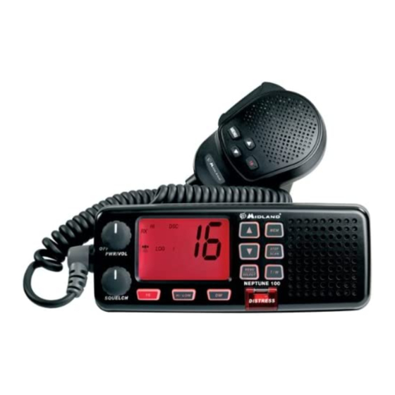
Hi/LOW SQUELCH DISTRESS PWR/VOL - Turns NEPTUNE 100 on/off and regulates audio volume reception. SqUELCH knob – Regulates the squelch level (noise silencer in absence of signals). Button 16 – Pressing the 16 button provides quick access to channel 16. -
Page 8: Back Panel (Connections)
3.2 Back panel (connections) Warning! Faulty connections or short-circuits may seriously damage NEPTUNE 100. Before attempting any connections, consult the specialized sections of this manual. DC 13,8V 1. Antenna socket This SO 239 socket is for connecting an appropriate antenna. -
Page 9: Installation
4. INSTALLATION 4.1 Contents of package Before using your transceiver, ensure that your package is complete and contains: Mounting bracket DC power cord with integrated protecting fuse Knobs (2 pieces) Mounting piece for microphone Self-threading screws for mounting bracket (4 pieces) Screws for mounting bracket (4 pieces) Washers (4 +4 pieces) Nuts (4 pieces) -
Page 10: Location For The Transceiver
Is far enough away from any device sensitive to magnetic/electromagnetic fields (e.g. compass) in order to avoid interference during their use. • Allows for accessibility to the front panel of NEPTUNE 100. • Provides easy connection to a power supply, for the antenna and for other cables. •... -
Page 11: Adjustment Of Angle
with those on both sides of the transceiver (you can choose the preferred notch in order to best adjust the angle of the transceiver’s front panel for ease of viewing and use (15 of variation for each notch). Mount the mounting knobs on the two sides of the bracket to soundly fix the transceiver. Keep the transceiver and microphone at a distance of at least 1 meter from all other magnetic devices (e.g. -
Page 12: Connections
We suggest using the supplied cable. 4.7.b GPS device If your NEPTUNE 100 transceiver is connected to a GPS receiver, such as the GR213, you can obtain and view NMEA information relative to the current position the vessel (latitude and longitude) and the local time with respect to Greenwich Mean Time (GMT). -
Page 13: Basic Operation
5.5 Transmission and reception Transmitting without a perfectly functioning antenna may seriously damage the transceiver. The PTT (Push-To-Talk) button is located on the external microphone of your NEPTUNE 100. To transmit: Ensure that no one else is speaking. Hold down the PTT button on the microphone. -
Page 14: Selecting High And Low Transmission Power
5.6 Selecting high and low transmission power The transmission phase absorbs the most energy. To reduce the risk of wearing out the battery, we recommend selecting low transmission power when transmitting over short distances. Hold the H/L button down (on the radio): Lo (low power) appears on the display. When transmitting or receiving over long distances or with weak signals, press the H/L button again. -
Page 15: Scanning Functions
When a signal is detected, the scanning pauses on that channel (RX displayed) and remains blocked until the signal ends. Before the scanning automatically starts again, NEPTUNE 100 waits for a 3,4 seconds in case the user wants to transmit. -
Page 16: Mem Function
Triple Watch This function allows the monitoring of three channels at the same time: channel 16, channel in use and one channel of your choice. Procedure: • Press T/W, until “TRIPLE WATCH” blinks on the display; • Select the secondo channel you want to monitor; CH16 is automatically monitored; •... -
Page 17: Use With Gps
You may also insert the coordinates manually. 7.2 GPS information on the display Once connected the GPS (GR213) to your NEPTUNE 100 (PS 2 connector), the symbol [DISEGNO] will blink on the display till your position will be established. Then, the radio display will show the... -
Page 18: Digital Selective Calling (Dsc)
8.3 Navigating the DSC menu NEPTUNE 100 offers many DSC functions. For this reason it was created Once inside a sub-menu, you can return at any time to the main menu by pressing the ... -
Page 19: Group Calling (Group Call)
The transmission is sent and WAITING ACK will blink on the display; if your call is confirmed by the other party, the display shows his name and you will hear a beep. If you push MENU/SELECT the display indicates the channel previously selected and the beep will stop; instead if you push any other channel, you will exit the individual call. -
Page 20: Dsc Distress Call
8.7 DSC DISTRESS call 8.7.a Sending a DISTRESS call IMPORTANT! You can only send a DSC call if you have been assigned an individual MMSI code and this code has been programmed into the transceiver (otherwise the following commands will be deactivated). Sending a distress call without founded reason is a criminal offence. -
Page 21: Stand By Option
If the MMSI owner code has been programmed previously with name in the directory, the name of the caller appears too. Every time NEPTUNE 100 receives a call (distress, individual or general) an entry will be stored in the list of registered calls “LOG”. -
Page 22: Customization
10. CUSTOMIZATION 10.1 “ Log” (list of registered calls) With this menu you can consult a directory of the latest registered incoming calls, like you do with your cellular phone. • Hold down MENU/SELECT till the display shows DSC CALL •... -
Page 23: Gps
For a better efficiency of the DSC service, we suggest you insert coordinates and time. If NEPTUNE 100 is connected to a compatible GPS receiver (GR213), the setting of these data is not compulsory. -
Page 24: Display/Keypad Backlight
With long pressures of the MENU/SELECT button, you will exit menu by menu. 10.7 Band Edit This function may be activated only with the optional programming kit PRG NEPTUNE 100. It allows the selection of the following bands: USA-CANADA-INTERNATIONAL (default) 10.8 LCD contrast... -
Page 25: Atis" (Setting Of Atis Code And Activation -Deactivation Of Automatical Transmission)
10.10 “ATIS” (Setting of ATIS code and activation –deactivation of automatic transmission) Your marine transceiver is able to activate, if necessary, an automatic transmission of your ATIS identification code each time the PTT is released. This function is only used when navigating in internal navigable European waters which require automatic transmission of identification. -
Page 26: Programming And Selection Of Private Channels
12. MAINTENANCE 12.1 Maintenance and warnings NEPTUNE 100 is a marine VHF transceiver that conforms to IPX7 standard, making the transceiver very reliable when used correctly. The device was designed so as to avoid requiring maintenance. To keep your transceiver in optimal... -
Page 27: Troubleshooting
Other interference devices Move other interference (televisions, computers, devices further from transceivers, etc.) too close to NEPTUNE 100 NEPTUNE 100 Impossible to Some channels operate only on Tune to another channel transmit or use high low power or are only for reception... -
Page 28: Technical Specifications
14 TECHNICAL SPECIFICATIONS Channels .................All 57 international marine channels Frequency generation..................... PLL synthesizer Frequency range .................TX from 156.025 to 157.424 MHz ....................RX from 156.300 to 162.000 MHz Antenna Impedance ......................50 Ohm Power supply .........................12 Vdc Operating temperature ..................from -15°C to +55°C Duty cycle ..........................5/5/90 Size........................72×177×146 mm Weight (device only) ...................... -
Page 29: Frequency Table
15. FREqUENCY TABLE INTERNATIONAL (INT)) INTERNATIONAL (INT) Frequency (MHz) Frequency (MHz) Mode Note Mode Note 156.050 160.650 156.075 160.675 156.100 160.700 156.125 160.725 156.150 160.750 156.175 160.775 156.200 160.800 156.225 160.825 156.250 160.850 156.275 160.875 156.300 156.300 156.325 160.925 156.350 160.950 156.375 156.375...
Need help?
Do you have a question about the NEPTUNE 100 and is the answer not in the manual?
Questions and answers