Table of Contents
Advertisement
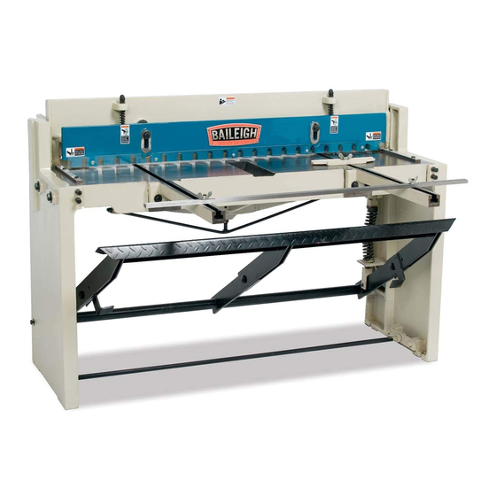
OPERATOR'S MANUAL
FOOT SHEAR
MODEL: SF-5216E
Baileigh Industrial, Inc.
P.O. Box 531
Manitowoc, WI 54221-0531
Phone: 920.684.4990
Fax: 920.684.3944
sales@baileigh.com
REPRODUCTION OF THIS MANUAL IN ANY FORM WITHOUT WRITTEN APPROVAL OF BAILEIGH INDUSTRIAL, INC.
IS PROHIBITED. Baileigh Industrial, Inc. does not assume and hereby disclaims any liability for any damage or loss
caused by an omission or error in this Operator's Manual, resulting from accident, negligence, or other occurrence.
Rev. 09/2015
© 2015 Baileigh Industrial, Inc.
Advertisement
Table of Contents

Related Manuals for Baileigh SF-5216E


Summary of Contents for Baileigh SF-5216E
- Page 1 REPRODUCTION OF THIS MANUAL IN ANY FORM WITHOUT WRITTEN APPROVAL OF BAILEIGH INDUSTRIAL, INC. IS PROHIBITED. Baileigh Industrial, Inc. does not assume and hereby disclaims any liability for any damage or loss caused by an omission or error in this Operator’s Manual, resulting from accident, negligence, or other occurrence.
-
Page 2: Table Of Contents
Table of Contents THANK YOU & WARRANTY ..................1 INTRODUCTION ......................3 GENERAL NOTES ......................3 SAFETY INSTRUCTIONS ....................4 SAFETY PRECAUTIONS ....................6 TECHNICAL SPECIFICATIONS ..................8 TECHNICAL SUPPORT ....................8 UNPACKING AND CHECKING CONTENTS ..............9 Cleaning ........................9 TRANSPORTING AND LIFTING .................. -
Page 3: Thank You & Warranty
THANK YOU & WARRANTY Thank you for your purchase of a machine from Baileigh Industrial. We hope that you find it productive and useful to you for a long time to come. Inspection & Acceptance. Buyer shall inspect all Goods within ten (10) days after receipt thereof. Buyer’s payment shall constitute final acceptance of the Goods and shall act as a waiver of the Buyer’s rights to inspect or... - Page 4 Baileigh Industrial makes every effort to ensure that our posted specifications, images, pricing and product availability are as correct and timely as possible. We apologize for any discrepancies that may occur. Baileigh Industrial reserves the right to make any and all changes deemed necessary in the course of business including but not limited to pricing, product specifications, quantities, and product availability.
-
Page 5: Introduction
After receiving your equipment remove the protective container. Do a complete visual inspection, and if damage is noted, photograph it for insurance claims and contact your carrier at once, requesting inspection. Also contact Baileigh Industrial and inform them of the unexpected occurrence. Temporarily suspend installation. -
Page 6: Safety Instructions
IMPORTANT PLEASE READ THIS OPERATORS MANUAL CAREFULLY It contains important safety information, instructions, and necessary operating procedures. The continual observance of these procedures will help increase your production and extend the life of the equipment. SAFETY INSTRUCTIONS LEARN TO RECOGNIZE SAFETY INFORMATION This is the safety alert symbol. - Page 7 SAVE THESE INSTRUCTIONS. Refer to them often and use them to instruct others. PROTECT EYES Wear safety glasses or suitable eye protection when working on or around machinery. PROTECT AGAINST NOISE Prolonged exposure to loud noise can cause impairment or loss of hearing.
-
Page 8: Safety Precautions
SAFETY PRECAUTIONS Metal working can be dangerous if safe and proper operating procedures are not followed. As with all machinery, there are certain hazards involved with the operation of the product. Using the machine with respect and caution will considerably lessen the possibility of personal injury. However, if normal safety precautions are overlooked or ignored, personal injury to the operator may result. - Page 9 12. Use eye and ear protection. Always wear ISO approved impact safety goggles. Wear a full- face shield if you are producing metal filings. 13. Do not overreach. Maintain proper footing and balance at all times. DO NOT reach over or across a running machine.
-
Page 10: Technical Specifications
(other than die sets and blades). For specific application needs or future machine purchases contact the Sales Department at: sales@baileigh.com, Phone: 920.684.4990, or Fax: 920.684.3944. Note: The photos and illustrations used in this manual are representative only and may not depict the actual color, labeling or accessories and may be intended to illustrate technique only. -
Page 11: Unpacking And Checking Contents
UNPACKING AND CHECKING CONTENTS Your Baileigh machine is shipped complete. Separate all parts from the packing material and check each item carefully. Make certain all items are accounted for before discarding any packing material. WARNING: SUFFOCATION HAZARD! Immediately discard any plastic bags and packing materials to eliminate choking and suffocation hazards to children and animals. -
Page 12: Transporting And Lifting
TRANSPORTING AND LIFTING IMPORTANT: Lifting and carrying operations should be carried out by skilled workers, such as a truck operator, crane operator, etc. If a crane is used to lift the machine, attach the lifting chain carefully, making sure the machine is well balanced. Follow these guidelines when lifting with truck or trolley: •... -
Page 13: Installation
INSTALLATION IMPORTANT: Consider the following when looking for a suitable location to place the machine: • Overall weight of the machine. • Weight of material being processed. • Sizes of material to be processed through the machine. • Space needed for auxiliary stands, work tables, or other machinery. •... -
Page 14: Overall Dimensions
OVERALL DIMENSIONS 62.00" (1,574) 57.00" (1,447.8) 60.00" (1,524) 73.00" (1854.2) 16.50" (419.1) 21.00" (533.4) -
Page 15: Getting To Know Your Machine
GETTING TO KNOW YOUR MACHINE Back Side... - Page 16 Item Description Function Table Machined surface for loading material Hold down Spring loaded bar to secure material Safety shield Clear plastic guard attached to hold down Foot pedal Used to lower the top blade for shearing Front arm extensions Provides material support at load end Front Stop Adjustable with T-slot Miter guide...
-
Page 17: Assembly And Set Up
ASSEMBLY AND SET UP... - Page 18 Spare clevis pin (long) Spare clevis pin (short)
- Page 19 Item Description Qty. Shear Body Foot Pedal Pedal Pivot Shaft Miter Guide Back Gauge Shaft Front Arm Extensions Micro adjuster Assembly Front Stop Back Gauge Stop Hardware T-Bolt M12 Flat Washer M12 Wing Nut M12 Hex Head Bolt M12 x 45mm Hex Head Bolt M10 x 20mm Clevis Pin (short) Cotter Pin 3/32 x 1”...
-
Page 20: Machine Assembly
Machine Assembly The foot pedal needs to be attached to the shear frame. See (fig.3) below for the finished pedal assembly. figure 3 Installation Procedure 1. Lay the pedal on the floor and insert (2) short clevis pins as indicated by the arrows in (fig. 4). Secure with cotter pins. - Page 21 Installing Front Extension Rails 1. Attach (4) M12 hex bolts and (4) flatwashers to the machined rail pads as in (fig. 6). 2. Slide the rail onto the capscrews and behind the flatwashers. 3. Line up the rail channel with the channel on the table, making sure the top machined surfaces are flush.
- Page 22 Installing the Rear Gauge Shafts 1. Slide the gauge shafts into the housing hole with the scales facing up and tighten each capscrew as shown in (fig. 9). 2. Slide the micro-adjustment assemblies onto the shafts and position them at the same location using the scales as a reference.
-
Page 23: Machine Functions
MACHINE FUNCTIONS Foot Pedal Stepping down on the foot pedal does two things. First it lowers the hold downs which keep the piece part from moving during a cut. Second it lowers the top blade past the lower blade to shear the material. Front and Rear Extension Rods figure 12 The front extensions help support large sheets of material and the rear... -
Page 24: Material Support Arm
Material Support Arm CAUTION: When handling large piece parts, you may require assistance in handling the piece as it exits the blades. Failure to adequately support the piece part may result in the piece falling and causing bodily injury. The two material support arms (A) attach to the front of the shear as shown in (fig. -
Page 25: The Shearing Cycle
THE SHEARING CYCLE WARNING: Always wear proper eye protection with side shields, safety footwear, and leather gloves to protect from burrs and sharp edges. The shearing blade poses an amputation hazard. Make sure no body part or clothing is near the specific hazard. Failure to follow this warning could result in severed or crushed fingers. -
Page 26: Material Selection
MATERIAL SELECTION CAUTION: It must be determined by the customer that materials being processed through the machine are NOT potentially hazardous to operator or personnel working nearby. When selecting materials keep these instructions in mind: • Material must be clean and dry. (without oil) •... -
Page 27: Blade Clearance
BLADE CLEARANCE The blade gap on the shear was set at the factory. At this setting it will shear mild steel up to 16 ga. (1.52mm) and stainless steel up to 20 ga. (.912mm). To measure the blade gap, gradually lower the top blade and measure the gap going from left to right while facing the rear of the machine. -
Page 28: Setup And Adjustments
SETUP AND ADJUSTMENTS hold down Hold down Adjustment piece part The hold down, when properly adjusted, secures the piece part while being sheared, and prevents the operator’s fingers from getting in the cutting blades path. The ideal adjustment allows only enough clearance to slide the piece part under the hold down. -
Page 29: Adjusting The Blade
5. If you notice a gap between the two blade surfaces, contact the service department at Baileigh Industrial (920.684.4990) for assistance in adjusting the bow. 5. Using a sheet of paper, make a series of cuts along the length of the blade. The paper should cut cleanly. -
Page 30: Lubrication And Maintenance
LUBRICATION AND MAINTENANCE WARNING: Maintenance should be performed on a regular basis by qualified personnel. Always follow proper safety precautions when working on or around any machinery. Daily Maintenance • Check daily for any unsafe conditions and fix immediately. (Cracked castings, welds, worn pins and shafts) •... -
Page 31: Parts Identification Drawing
PARTS IDENTIFICATION DRAWING... -
Page 33: Parts List
Parts List Item Description Work Table Frame Pressing Plate Right Stand Left Stand Connecting Rod Hex Bolt M12 x 45mm Spring Threaded Stud Acorn Nut M12 Hex Bolt M12 x 80mm Flatwasher M12 Finger Guard Round Head Screw M6 x 16mm Workpiece Stop Scale Hex Bolt M8 x 20mm... - Page 34 Item Description Straightener Rod Hex Nut M14 Hex Nut M12 Adjusting Bolt M16 Flatwasher M12 Flatwasher M16 Round Head Screw M4 x 10mm Spring Lower Pin Upper Connecting Block Lower Connecting Block Threaded Stud Flatwasher M16 Hex Nut M16 Connecting Angle Indicator Hex Bolt M12 x 30mm Upper Pin...
- Page 35 Item Description Gauge Shaft Hex Nut M16 Workpiece Pushing Plate Flatwasher M12 T-Style Bolt Wing Nut M12 Small Workpiece Push Plate Cotter Pin Straightener End Bracket Straightener Center Bracket Tie Bar Threaded Rod Hex Bolt M10 x 40mm...
-
Page 36: Troubleshooting
Adjust hold down gap. Not enough hold down force. CUTS NOT SQUARE Adjust blade gap. Blade gap is unequal along length. Consult the Baileigh service Blade has a bow. department. (920.684.4990) Improper blade gap. Widen gap for thicker material. CAN NOT CUT... - Page 37 NOTES...
- Page 38 NOTES...
- Page 39 NOTES...
- Page 40 , WI 54220 UFEK RIVE ANITOWOC : 920. 684. 4990 F : 920. 684. 3944 HONE www.baileigh.com BAILEIGH INDUSTRIAL, INC. 1455 S. C , CA 91761 AMPUS VENUE NTARIO : 920. 684. 4990 F : 920. 684. 3944 HONE BAILEIGH INDUSTRIAL LTD. U...
Need help?
Do you have a question about the SF-5216E and is the answer not in the manual?
Questions and answers