
Related Manuals for PAE T6M

Summary of Contents for PAE T6M
- Page 1 T6M Service Manual Issue 1 PARK AIR ELECTRONICS LTD NORTHFIELDS MARKET DEEPING PETERBOROUGH PE6 8UE TEL:(01778) 345434 FAX:(01778) 342877...
-
Page 2: Copyright Information
♦ The mobile transmitter frequency and parameters should be checked by authorised service personnel before use, and at least yearly thereafter. T6M SERIES MOBILE SERVICE MANUAL – SM/16/1.0 Page i... -
Page 3: Safety Information
DO NOT connect an external RF power amplifier to this equipment. Patent Information ♦ The Linear Modulation techniques described in this publication are subject to Patents issued to the British Technology Group (BTG) and Linear Modulation Technology (LMT) Page ii T6M SERIES MOBILE SERVICE MANUAL – SM/16/1.0... - Page 4 ♦ Patent No’s are: BTG – UK 2161661, 2163326; US 4691375, 4679243: LMT - UK 2243058, 2274231, 2272589, 2293935: EU 0447237, 0725495, 0598585, 0648012, 0706259: US 5249202, 5381108, 5507017, 5623226. T6M SERIES MOBILE SERVICE MANUAL – SM/16/1.0 Page iii...
- Page 5 Table Of Contents Section INTRODUCTION SPECIFICATION EQUIPMENT DESCRIPTION INSTALLATION OPERATION PERFORMANCE TESTING DETAILED CIRCUIT DESCRIPTION CIRCUIT DIAGRAMS BOARD LAYOUTS GENERAL ASSEMBLIES PARTS LIST ACCESSORIES AND LEADS LOOMS Page iv T6M SERIES MOBILE SERVICE MANUAL – SM/16/1.0...
- Page 6 Date Incorporated Reason for Change If you find any errors or omissions in this manual, or you have any suggestions for improvements please write to the address shown on the front page. T6M SERIES MOBILE SERVICE MANUAL – SM/16/1.0 Page v...
-
Page 7: Introduction
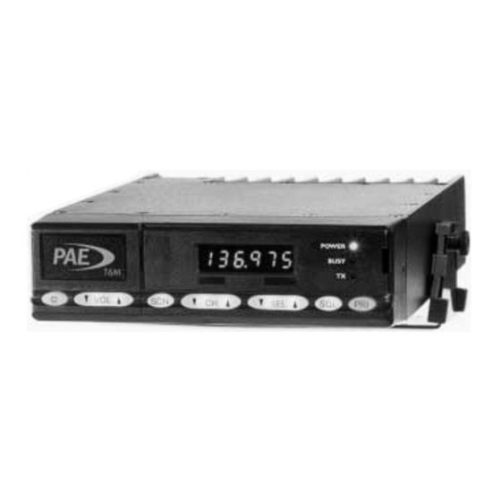
INTRODUCTION 1 INTRODUCTION The Park Air Electronics (PAE) mobile transceiver Type T6M is a multi- channel VHF AM equipment operating in the frequency range 118 to 137 MHz with a bandwidth of 8.33 or 25 kHz. The transceiver is designed for vehicle mounting via a bracket, usually around the dash board area. -
Page 8: Specification
2.2 Receiver Sensitivity -100dBm Selectivity 50dB @ 8.33kHz, 60dB @ 25kHz Intermodulation 60dB Spurious and Image Rejection 75dB Audio Power Output 4 Watts. Distortion <10% THD RF Input Impedance 50 ohms T6M SERIES MOBILE SERVICE MANUAL – SM/16/1.0 Page 2-1... - Page 9 S P E C I F I C A T I O N S 2.3 Transmitter RF Output Power, Nominal 8 Watts Spurious -46dBm Harmonics -36dBm Audio Modulation RF Load Impedance 50 ohms ± 1.0ppm (normal) Frequency Stability Page 2-2 T6M SERIES MOBILE SERVICE MANUAL – SM/16/1.0...
- Page 10 E Q U I P M E N T D E S C R I P T I O N 3. Section Index Section Index General T6M Series Mobile Front panel Mobile Radio Programming 3.3.1 Programming Interface Lead 3.3.2 Programming Software T6M SERIES MOBILE SERVICE MANUAL – SM/16/1.0 Page 3-1...
-
Page 11: Installation
E Q U I P M E N T D E S C R I P T I O N 3.1 General The T6M series mobile radio is designed to operate in single frequency simplex mode on the International Air Band allocation (118-137 MHz mobile transmit and receive). - Page 12 E Q U I P M E N T D E S C R I P T I O N available for this purpose, which runs on a PC. The software is available on 3.5” floppy disks. The software contains built in help features. T6M SERIES MOBILE SERVICE MANUAL – SM/16/1.0 Page 3-3...
- Page 13 E Q U I P M E N T D E S C R I P T I O N This page blank intentionally Page 3-4 T6M SERIES MOBILE SERVICE MANUAL – SM/16/1.0...
-
Page 14: Table Of Contents
4.8Troubleshooting Flow Chart - General Operation............4-8 Figure 4-1 Mobile Radio Mounting Bracket - Dimensions Figure 4-2 Mobile Connections Figure 4-3 Antenna Locations Figure 4-4 Antenna Radiation Patterns Figure 4-5 - T6M Series General Troubleshooting Flow Chart T6M SERIES MOBILE SERVICE MANUAL – SM/16/1.0 Page 4-1... -
Page 15: General
This type of electrical system has the negative battery terminal connected directly to the vehicle chassis. For vehicles with a 24 V battery or where there must be isolation between the battery and the equipment, a suitable DC-DC converter should be used. Page 4-2 T6M SERIES MOBILE SERVICE MANUAL – SM/16/1.0... -
Page 16: Selecting A Mounting Location
The other provides a friction mount allowing the mobile radio to be tilted to the desired angle. 52 mm 189 mm Hole 4.5 mm diameter 150 mm Figure 4-1 Mobile Radio Mounting Bracket - Dimensions T6M SERIES MOBILE SERVICE MANUAL – SM/16/1.0 Page 4-3... -
Page 17: Power Cable Installation
Route the power cable to the battery. If there is excess cable, cut it to the required length. If it is necessary to drill a hole in the firewall or bulkhead to route the cable through then fit a grommet and seal it when the installation is complete. Page 4-4 T6M SERIES MOBILE SERVICE MANUAL – SM/16/1.0... -
Page 18: T6M Series Mobile Service Manual – Sm/16/1.0 Page
If required connect the ignition sense lead to the ignition switched supply on the vehicle. Plug the power cable into the power supply in-line connector on the mobile radio, and reconnect the positive lead to the battery. T6M SERIES MOBILE SERVICE MANUAL – SM/16/1.0 Page 4-5... -
Page 19: Antenna Connection
Figure 4-3 Antenna Locations Figure 4-4 Antenna Radiation Patterns Warning: Under no circumstances should the antenna be located near to a fuel filler cap (i.e. not closer than 300mm). Page 4-6 T6M SERIES MOBILE SERVICE MANUAL – SM/16/1.0... -
Page 20: Operation
Figure 4-2), pins 3 and 7. 4.7 Serviceability Check - General Operation Once the mobile radio, its accessories and antenna are installed, carry out a serviceability check as follows: T6M SERIES MOBILE SERVICE MANUAL – SM/16/1.0 Page 4-7... -
Page 21: Troubleshooting Flow Chart - General Operation
(see Figure 4-5 ) For reference: SPU : Signal Processing Unit (PCB) EXP : Expander card (PCB) RFU : Radio Frequency Unit (PCB) FPU : Front Panel Unit (PCB) : Power Amplifier (PCB) Page 4-8 T6M SERIES MOBILE SERVICE MANUAL – SM/16/1.0... -
Page 22: Figure 4-5 - T6M Series General Troubleshooting Flow Chart
INSTALLATION Figure 4-5 - T6M Series General Troubleshooting Flow Chart T6M SERIES MOBILE SERVICE MANUAL – SM/16/1.0 Page 4-9... - Page 23 INSTALLATION This page blank intentionally Page 4-10 T6M SERIES MOBILE SERVICE MANUAL – SM/16/1.0...
- Page 24 Reading the personality from a mobile ............5-14 5.8.8 Printing a personality report................5-14 5.8.9 Getting a mobile’s serial number and firmware version.........5-14 5.8.10 Programming new firmware into a mobile ............5-14 Test Mode ....................5-15 T6M SERIES MOBILE SERVICE MANUAL – SM/16/1.0 PAGE 5-1...
-
Page 25: Modes Of Operation
Both the CH and SEL buttons auto-repeat when held down. If the highest programmed frequency is reached when stepping up through the channels, the mobile wraps round to the lowest programmed frequency. If the lowest programmed PAGE 5-2 T6M SERIES MOBILE SERVICE MANUAL – SM/16/1.0... - Page 26 If the display blanks then it may be reinstated by pressing either volume button, or by pressing the PTT button. To transmit, press the PTT button and talk. Whilst you are transmitting the red Tx LED will light. T6M SERIES MOBILE SERVICE MANUAL – SM/16/1.0 PAGE 5-3...
- Page 27 It has two possible seek modes, “Hold” and “Pause”. If Hold mode is programmed then the mobile remains on the channel until you press the CH é button to resume scanning. PAGE 5-4 T6M SERIES MOBILE SERVICE MANUAL – SM/16/1.0...
- Page 28 Squelch is automatically enabled when scan mode is selected. Channels may be programmed into more than one scan group. Scan and priority modes are mutually exclusive. T6M SERIES MOBILE SERVICE MANUAL – SM/16/1.0 PAGE 5-5...
- Page 29 Squelch must be open for seconds seconds this time before an inactive channel is considered busy. Offset On or off When on, the mobile scans channels for the strongest frequency within a 25kHz channel. PAGE 5-6 T6M SERIES MOBILE SERVICE MANUAL – SM/16/1.0...
- Page 30 Attempting to transmit on a channel with the “transmit inhibit” option set to always inhibit. • Attempting to transmit on a busy channel with the “inhibit if busy” option selected. • Imminent transmitter timeout. T6M SERIES MOBILE SERVICE MANUAL – SM/16/1.0 PAGE 5-7...
-
Page 31: Key Beeps
F16 Low supply voltage. May be caused by low power supply voltage or high resistance connections. F32 High voltage. Probably caused by a power supply fault. PAGE 5-8 T6M SERIES MOBILE SERVICE MANUAL – SM/16/1.0... - Page 32 Select the File | New option from the menu. This resets all options to default values and clears all the entries in the frequency table except one. Select the “General” page. T6M SERIES MOBILE SERVICE MANUAL – SM/16/1.0 PAGE 5-9...
- Page 33 If you limit transmit time and enable warning beeps then you will hear warning sounds 10 seconds before the mobile stops transmitting and again when transmitting stops. PAGE 5-10 T6M SERIES MOBILE SERVICE MANUAL – SM/16/1.0...
- Page 34 The Tx Inhibit column determines when a mobile may transmit. If inhibit is set to Never, by entering N in this column, then transmit is always allowed. This allows you to transmit on this frequency even if it is busy. T6M SERIES MOBILE SERVICE MANUAL – SM/16/1.0 PAGE 5-11...
- Page 35 If you have programmed a large number of frequencies then use the Find channel button to find quickly a frequency in the frequency table. Enter the frequency you are looking for, then click Find it. PAGE 5-12 T6M SERIES MOBILE SERVICE MANUAL – SM/16/1.0...
- Page 36 The progress of the programming operation is displayed on the status line at the bottom of the programmer window. When programming is complete, switch off the mobile and disconnect the programming lead. T6M SERIES MOBILE SERVICE MANUAL – SM/16/1.0 PAGE 5-13...
- Page 37 “ESN” is short for Electronic Serial Number. The first part of the number describes the mobile’s type and firmware version. The second part is a serial number unique to your mobile. 5.8.10 Programming new firmware into a mobile WARNING! PAGE 5-14 T6M SERIES MOBILE SERVICE MANUAL – SM/16/1.0...
-
Page 38: Test Mode
1 to 240 inclusive. Alter the power level setting whilst the mobile is receiving, then press the microphone PTT button to observe the result. The mobile should be adjusted to achieve 8 watts T6M SERIES MOBILE SERVICE MANUAL – SM/16/1.0 PAGE 5-15... - Page 39 “S” and the speaker sounds two short pips. If the key sequence is incorrect then the display shows “nS” and the speaker sounds a single, longer tone to indicate that the new setting has not been saved. PAGE 5-16 T6M SERIES MOBILE SERVICE MANUAL – SM/16/1.0...
- Page 40 PERFORMANCE TESTING 6 Section Index 6.1 Introduction ....................6-2 6.2 Test Equipment ................... 6-2 6.3 Power Supply ....................6-2 6.4 Transmitter ....................6-2 6.5 Receiver ...................... 6-3 6.6 TX Power Adjust..................6-3 T6M SERIES MOBILE SERVICE MANUAL – SM/16/1.0 Page 6-1...
- Page 41 Section 5.9). 2. Key up the mobile and, with no modulation applied, check the following: Current draw is <6.2A Transmit power is >7W and <10W III. Transmitter frequency is within 1.0ppm Page 6-2 T6M SERIES MOBILE SERVICE MANUAL – SM/16/1.0...
- Page 42 Check that the distortion figure is <5% for 30% modulation and is <10% for 90% modulation. Check that the current drawn is 2A 6.6 TX Power Adjust To adjust the TX Power, please refer to Section 5.9. T6M SERIES MOBILE SERVICE MANUAL – SM/16/1.0 Page 6-3...
Need help?
Do you have a question about the T6M and is the answer not in the manual?
Questions and answers