Table of Contents
Advertisement
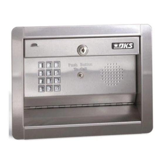
Installation/Owner's Manual
Use this manual for circuit board 1506-010 Revision G or higher.
1504
1504
1504
with Intercom
1506
1506
1506
Date Installed:
Installer/Company Name:
Phone Number:
Leave Manual with Owner
UL Listed
Programmable Stand Alone Digital Keypad Entry Devices
1
4
7
1 5
0 4
- 0 9
1 5
0 6
- 0 9
Copyright 2017 DoorKing, Inc. All rights reserved.
Models 1504 / 1506
Models 1504 / 1506
Models 1504 / 1506
Control a main entry point plus an additional entry point.
F l u
s h
M o
u n
t
2
3
5
P u
P u
6
s h
s h
8
B u
B u
T o
T o
t t o
t t o
9
C a
C a
n
n
0
l l
l l
6
F l u
s h
M o
u n
t
1
2
4
3
5
6
7
8
9
0
6
Circuit Board
Serial Number
and Revision Letter:
1506-065-K-6-17
S u
r f a
1
2
3
4
5
P u
P u
7
6
s h
s h
8
T o
T o
9
0
1 5
0 4
- 0 8
6
S u
r f a
c e
1
2
4
3
5
6
7
8
9
0
1 5
0 6
- 0 8
6
Model Number
Copyright 2009 DoorKing, Inc. All rights reserved.
c e
M o
u n
t
B u
B u
t t o
t t o
C a
C a
n
n
l l
l l
M o
u n
t
Advertisement
Table of Contents

Related Manuals for DoorKing 1504-096

Summary of Contents for DoorKing 1504-096
- Page 1 - 0 8 - 0 9 Date Installed: Installer/Company Name: Model Number Circuit Board Serial Number Phone Number: and Revision Letter: Leave Manual with Owner Copyright 2017 DoorKing, Inc. All rights reserved. UL Listed Copyright 2009 DoorKing, Inc. All rights reserved.
-
Page 3: Table Of Contents
TABLE OF CONTENTS SPECIFICATIONS 1504 Specifications 1506 Specifications Important Notices SECTION 1 - INSTALLATION 1.1 Remove Faceplate from Cabinet 1.2 Surface Mount 1.3 Flush Mount 1.4 Terminal Wiring 1.5 1504 AiPhone Intercom Station Connections 1.6 Secondary Keypad Wiring SECTION 2 - PROGRAMMING 2.1 Re-Programming the Master Code 2.2 Relay Strike Time 2.3 X Strikes for Invalid Entry Code Attempts... -
Page 4: Specifications
Push Button Push Button To Call To Call 2.5” 6.125” 5” 3” 2.875” Mounting Note: Can be mounted on a DoorKing gooseneck mounting post. t t o t t o 875” Dia 1.75” 1.125” 1.125” Bottom View 1504 Flush Mount Dimensions... -
Page 5: 1506 Specifications
Side Front Mounting Holes 1/2” 6.5” Knock-out Mounting Note: 4.5” 5.25” Can be mounted on a DoorKing gooseneck mounting post. 1506 Flush Mount Dimensions P/N 1506-096 Side Views Front Views Rough-In Box Flush Box 4.25” Flush Box Bolt holes (4) to secure flush 7”... -
Page 6: Important Notices
Important Notices • Prior to starting the installation, become familiar with the instructions, illustrations and wiring diagrams in this manual. • Never mount this device to a moving gate or gate panel, or next to a gate that causes vibration to the fence, such as a spring- loaded pedestrian gate. -
Page 7: Surface Mount
Mount on a Post wall or pilaster. They can be post mounted using a Use existing 4 holes in surface DoorKing mounting post (there are several different mount cabinet box to bolt on a styles available). Be sure keypad is securely mounted DoorKing mounting post. -
Page 8: Terminal Wiring
1506-010 1.4 Terminal Wiring Attach a separate 12 AWG wire to GND (earth ground). Attach the other end of this 4 - A switch closure to TERMINAL 11 wire to a good earth ground. will lock out all entry codes within the This can be a properly grounded metal TIME ZONE 1 lower and upper conduit, a cold water pipe, or a grounding... -
Page 9: 1504 Aiphone Intercom Station Connections
1.5 1504 Aiphone Intercom Station Connections These wire diagrams are provided for convenience only. For detailed wiring information on Aiphone products, visit their website at www.aiphone.com. 1504 Speaker Push to Call Button Intercom Station Capacitor 3-Wire System 47uF – AIPhone LEF Series Hands-Free Selective Call Systems These series of systems are purchased separately. -
Page 10: Secondary Keypad Wiring
1.6 Secondary Keypad Wiring Secondary Lighted Kepad P/N 1506-081 Surface Mount (Sold Separately) P/N 1506-091 Flush Mount (Sold Separately) Note: The secondary keypad has NO relays! Valid entry codes entered on the secondary keypad 1504/1506 Keypad Entry Device will activate the relays in the 1504/1506 keypad. 8-Conductor 22 AWG 1 5 9... -
Page 11: Section 2 - Programming
SECTION 2 - PROGRAMMING Before You Start Programming: IMPORTANT! Make sure the 1504/1506 has power and we suggest that you become familiar with programming instructions before beginning any programming. Keep a record of the programmed codes by completing the tables on pages 24 and 25. 2.1 Re-Programming the Master Code The Master Code has been pre-programmed at the factory to 9999. -
Page 12: Programming Four-Digit Entry Codes
2.4 Programming Four-digit Entry Codes Four-digit entry codes are entered on the Keypad preceded by “ # ” to allow the RESIDENT ACCESS. DO NOT confuse a FOUR-digit ENTRY code with a FIVE-digit ENTRY code (see section 2.8). 1. Press 0 2 and enter the MASTER CODE. -
Page 13: Programming Five-Digit Entry Codes
2.8 Programming Five-digit Entry Codes Five-digit entry codes are entered on the Keypad. DO NOT press # first when using five-digit entry codes. When the door input is activated by the five-digit entry code, the relay will deactivate one second after this input is activated, regardless of the programmed strike time. -
Page 14: Hold Boundary Programming
2.12 Hold Boundary Programming The entry system hold boundaries establish a set of four-digit entry codes that will latch Relay 1 ON, Relay 2 ON, or BOTH Relay 1 and Relay 2 ON (depending on the divide number programmed and the hold boundaries that have been programmed) indefinitely. -
Page 15: Section 3 - Operating Instructions
SECTION 3 - OPERATING INSTRUCTIONS 3.1 Four-digit Entry Codes To use a four-digit entry code, the # key MUST first be pressed then the four-digit code entered on the keypad. Four-digit entry codes can be programmed to operate either Relay 1 or Relay 2. When a four-digit code is entered on the keypad (preceded by #), the system checks its memory to see if the code is stored. -
Page 16: Hold Feature Operation
3.5 Hold Feature Operation The relay hold feature allows a set of four-digit entry codes to latch (or hold) a relay indefinitely. Any four-digit entry code that falls numerically within the hold boundaries will cause relay 1 to activate indefinitely if no four-digit divide number is programmed. -
Page 17: Time Zone Operation
3.6 Time Zone Operation The entry system has two time zone inputs. By using an external timer or switch, access can be denied to a group of four-digit entry codes during desired lockout times. Four-digit entry codes that fall numerically within a time zone boundary will cause a check of the time zone input when the code is entered. -
Page 18: Section 4 - Maintenance
SECTION 4 - MAINTENANCE 4.1 Troubleshooting • Have a good VOM meter to use when checking voltages and continuity. • Check power wiring wire size and distance. Improper wire size and too long wire run distances can cause problems. • Check the power transformer. -
Page 19: Log Tables
4.2 Log Tables Use the tables below to record data entered into the keypad system. Factory - 9999 Master Code (section 2.1) Relay Strike Time (section 2.2) 1st Digit 2nd Digit 3rd Digit 4th Digit Relay 1 Relay 2 Factory - 1 sec. Factory - 1 sec. - Page 20 Resident Four-Digit Entry Codes Make additional copies of this table as needed. NAME Four-Digit Entry Code NAME Four-Digit Entry Code 1506-065-K-6-17...
- Page 21 Resident Four-Digit Entry Codes Make additional copies of this table as needed. NAME Four-Digit Entry Code NAME Four-Digit Entry Code 1506-065-K-6-17...
-
Page 22: 1506-065
Programmable Stand Alone Digital Keypad Entry Devices Use this manual for circuit board 1506-010 Revision G or higher. 1506-065-K-6-17 Control a main entry point plus an additional entry point. www.doorking.com DoorKing, Inc. 120 S. Glasgow Avenue Inglewood, California 90301 UL Listed U.S.A.
Need help?
Do you have a question about the 1504-096 and is the answer not in the manual?
Questions and answers