
Related Manuals for Kewaunee AIR ALERT 600


Summary of Contents for Kewaunee AIR ALERT 600
- Page 1 AIR ALERT 600 FUME HOOD VELOCITY ALARM SUPREME AIR VENTURI FUME HOODS Installation and Operating Manual...
- Page 2 Issue 02 June 2017...
-
Page 3: Table Of Contents
Table of Contents Safety Safety Practices Warning Notices Precautions General Operating Conditions Environmental Conditions Electrical Safety Electrical Protection EMC Compliance Warning Labels Overview of the Airflow Monitor Operator Display Panel Display Features Displayed Alarms and Events Additional Alarms and Events LED Indication Audible Alarm Sounder Pushbuttons... - Page 4 Configuration & Calibration Configuration Start Up Calibration Calibration Notes Auxiliary Features and connections Temperature Sensor RS485 Coms output 8.1 Overview and connections 8.2 Configuration settings 8.3 Testing and troubleshooting 8.4 Config Manager Warranty 9.1 Limitation of warranty and liability...
-
Page 5: Safety
1. SAFETY... -
Page 6: Safety Practices
1.1 Safety Practices This document describes the general safety practices and precautions that must be observed when operating the Airflow Monitor. This advice is intended to supplement, not supersede, the normal safety codes in the user’s country. The information provided does not cover every safety procedure that should be followed. -
Page 7: General Operating Conditions
1.4 General Operating Conditions The Airflow Monitor and equipment have been designed and tested in accordance with the safety requirements of the International Electrotechnical Commission (IEC). The Airflow Monitor conforms to IEC61010-1 (Safety Requirements for electrical equipment for measurement, control and laboratory use) as it applies to IEC Class 1 (earthed) appliances, and therefore meets the requirements of EC directive 73/23/EEC. -
Page 8: Electrical Safety
1.6 Electrical Safety The Airflow Monitor and associated equipment are designed to protect the user from potential electrical hazards. This section describes some recommended electrical safety practices. Lethal voltages are present at certain points within the equipment. When the equipment is connected to mains power, removing the equipment covers is likely to expose live parts. -
Page 9: Electrical Protection
The electrical safety of the equipment is likely to be impaired if: • It has any signs of visible damage. • If it has been subjected to prolonged storage in unfavourable conditions. • If it has been subjected to severe stress during transportation. 1.7 Electrical Protection Observe the following electrical protection precautions: •... -
Page 10: Overview Of The Airflow Monitor
2. Overview of the Airflow Monitor... -
Page 11: Operator Display Panel
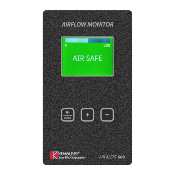
2.1 Operator Display Panel Velocity bar graph or Alarm Time Line Velocity display fpm or m/sec or Plain Text “Air Safe / Air Fail” Enter and +/- buttons for Menu Configuration and Calibration. ENTER / Mute also used as Mute button for audible alarm Caution Alarm Safe... -
Page 12: Display Features
2.2 Display Features The Airflow Monitor display has the following features: The digital display is a backlit, full color high resolution graphic unit with a visual display area of approximately 45 x 34mm. The display operates through the software allowing the generation of figures, wording and icons. -
Page 13: Displayed Alarms And Events
2.3 Displayed Alarms and Events Sash High – will be displayed when the Sash alarm is enabled and the sash is raised above the max safe working opening. Sash High will alternate on/off with the velocity reading. The Screen color will change to Amber. Ext Alarm –... -
Page 14: Led Indication
2.5 LED Indicators Instead of LED indicators the alarm unit screen backlight operates in 3 colors: - Red – Alarm Amber – Caution Green – Safe 2.6 Audible Alarm Sounder The airflow monitor has an audible sounder with local or remote mute facility. The audible alarm can be permanently disabled in the cal config menu. -
Page 15: Diagnostics Menu
2.8 Diagnostics Menu The airflow monitor has a diagnostics menu that shows current Input and Output status, Coms data and also includes an Alarm Test function. To access the diagnostics menu press the '+' and '-' buttons together whilst in the run screen. The diagnostics sub menu will appear showing the following options- a. - Page 16 Output Data:- Output 1 - Off / On Output 2 - Off / On Output 3 - Off / On Output Off = Output Open or not assigned Output On = Output Closed Sensor Data:- Airflow 00.0 % Temperature ◦C Airflow % = Output of airflow sensor in %, 100% = no airflow Temperature = Temperature in ◦C or ◦F - (when enabled) Done - returns to Diagnostics menu.
-
Page 17: External Connections
2.9 External Connections The airflow monitor has the following Inputs:- Input 1 Volt free input configurable for normally closed, normally open relays or Analogue 0-5VDC Input This input can be configured as:- Digital Input Functions (Closed or Open volt free contact):- Alarm disable Night set-back External alarm... - Page 18 Input 3 Volt free input configurable for normally closed, normally open relays or Analogue 0-5VDC Input This input can be configured as:- Digital Input Functions (Closed or Open volt free contact):- Alarm disable Night set-back External alarm Emergency Sash High High / Low Sash Warning Mains Fail...
- Page 19 Airflow Sensor RJ12 Connection socket for the face velocity airflow sensor. Optional Inputs Temperature Sensor Bespoke Temperature sensor for connection into inputs 1, 2 or 3 to give temperature display with high and low temperature alarms. PIR Occupancy Sensor Auxiliary PIR used for Close Sash alarm based on Fume Hood occupancy and sash position. Mains Fail battery unit.
-
Page 20: Functions And Operation
3. Functions & Operation... -
Page 21: Airflow Functions
3.1 Airflow Functions. The airflow monitor velocity display can be set up using the pushbutton menus to display airflow in units of m/sec or fpm and can also be set to show plain text "Air Safe" & "Air Fail" only. The airflow monitor has 3 programmable airflow alarms. -
Page 22: Input Functions
3.2 Input Functions. The airflow monitor has 3 programmable Inputs that can be set to analogue (0-5VDC), digital open or digital closed operation. Analogue input functions Temperature • Any Input set to Analogue - Temperature • Temperature is displayed alongside airflow velocity in ͦ F or ͦ C •... - Page 23 External alarm • When input configured as External alarm is activated • Screen Backlight Red • External Alarm toggles on /off with display -- (if configured) • Audible alarm sounds – can be muted via Enter pushbutton • External alarm relay operates (if configured) Emergency •...
- Page 24 Mains Fail (Optional extra feature) • When the input configured as Mains Fail is activated • Screen Backlight Red • Mains Fail is displayed • Audible alarm sounds • Audible can be muted via Enter pushbutton -- this silences the alarm if configured. Note - Not for use with Relay Interface unit -- AFA1000/E only.
-
Page 25: Components
4. Components... -
Page 26: Airflow Monitor
4.1 Airflow Monitor components 1 – Air Alert 600 Airflow Monitor 1 – Airflow Sensor c/w 2M RJ45 Sensor Cable 1 – Plug in type low voltage power supply with 5M Cable REFER TO INSTALLA TION INSTRUCTIONS BEF ORE CONNECTING www.tel-uk.com... -
Page 27: Auxiliary Components
4.2 Auxiliary Components The following auxiliary components are available for the airflow monitor:- Sash High Proximity Switch - Used for Sash High Alarm Sash High Micro Switch - Used for Sash High Alarm Personnel Sensor - Passive Infra-Red sensor - Used Close Sash Alarm Mains Fail Battery Unit - Used for Mains Fail Alarm Temperature Sensor - Used for Temperature display and alarms. -
Page 28: Installation
5. Installation... -
Page 29: Installation Of Standard Components
5.1 Installation of standard components The following section outlines the installation of the various components of the Airflow monitor. As the size and format of individual Fume Hoods varies considerably, specific instructions are not possible, though the principles outlined below should remain valid in all cases. The airflow monitor can be mounted on either side of the Fume Hood;... -
Page 30: Airflow Monitor Installation
5.2 Airflow Monitor Installation. Fume Hood Side Airfoil (Front View) Sensor Tube Cut Out Al a rm Panel Cut Out Di m ensi o ns 2 x Fi x i n g Hol e s for Alarm Panel Dimensions Al a rm Pl a te Screws Alarm Panel Cut Out... -
Page 31: Airflow Sensor Installation
5.3 Airflow Sensor installation. Sensor Tube Vent Hol e Al a rm panel Si d e View Fume Hood Front Panel In Line 1” Bell Mouth Bush Sensor Box 1” Bell Mouth Bush 1” Tube 1” Coupling Pl a n View Rj11 Sensor Cable to Alarm Fume Hood Front Panel... - Page 32 It is very important to position the SM6 airflow sensor in the correct position to give long term stable reading of the face velocity. Please read the INSTALLATION NOTES below and if in doubt contact us for further advice. INSTALLATION NOTES :- 1.
-
Page 33: Configuration & Calibration
6. Configuration & Calibration... -
Page 34: Configuration
6.1 Configuration. The airflow monitor can be configured via a Laptop or PC using a variety of ‘set up’ programs each designed for a particular application with a combination of inputs and outputs. This configuration can be changed via the key pad using the menu system if required or re-configured by re-connection of the laptop or PC. -
Page 35: Calibration
6.3 Calibration 1. Press Enter from the “Requires set up” screen or if the monitor is in the Run screen Press and Hold the Enter button for 5 seconds until the Main Menu is displayed. 2. Using the + / - buttons select SET UP, then select CALIBRATION, then enter the password (the factory default Password is 0-0-0-0), press Enter to continue. -
Page 36: Calibration Notes
6.4 Calibration Notes 1. When using a standard Fume Hood with Vertical Sliding sash, open the sash to the normal max safe working height for the Low Air sample. 2. For the Higher Air sample close the sash to approx. 50% of the opening used for the Lower Air sample. -
Page 37: Auxiliary Features And Connections
7. Auxiliary Features & Connections... -
Page 38: Temperature Sensor
7.1 Optional Input function - Temperature Sensor The airflow monitor can be fitted with a temperature sensor to display the fume hood temperature and give high and low temperature alarms. The temperature display can be hidden from view or shown alongside the airflow velocity. - Page 39 To Setup the Temperature input using the pushbutton menus: - 1. Press Enter from the “Requires set up” screen or if the monitor is in the Run Screen Press and Hold the Enter button for 5 seconds until the Main Menu is displayed. 2.
-
Page 40: Rs485 Coms Output
8. RS485 Coms Output... -
Page 41: Overview And Connections
8.1 Overview and connections The AFA1000 series has on board RS485 coms with 3 protocols:- Protocol Description Protocol for connection to TEL Configure Manager PC software and room controls Modbus Modbus RTU protocol BACnet BACnet MS/TP protocol (To connect to BACnet IP a 3 party router is required) See separate coms registers for further technical, compliance and register information:- AFA1000/1 Modbus Registers... -
Page 42: Configuration Settings
8.2 Configuration settings Note - when changing Protocols, the AFA1000 should be power cycled once re-configured to ensure the changed take effect. The TEL protocol has fixed parameters so cannot be adjusted in the field, to select the TEL protocol using the pushbutton menus: - Press Enter from the “Requires set up”... - Page 43 To Setup the AFA1000 with BACnet protocol using the pushbutton menus: - 1. Press Enter from the “Requires set up” screen or if the monitor is in the Run Screen Press and Hold the Enter button for 5 seconds until the Main Menu is displayed. 2.
-
Page 44: Testing And Troubleshooting
8.3 Testing and troubleshooting The AFA1000 diagnostics menu can be used to check the coms settings and operation once the AFA1000 coms parameter settings have been set up. From the run screen press the + & - buttons together to access the diagnostics screen. The diagnostics sub menu will appear showing the following options- a. -
Page 45: Config Manager
Modbus protocol troubleshooting guide Protocol Fault Remedy Modbus Device not present on Ensure the AFA1000 is in Run mode or Diagnostics screen, the Network coms are interrupted when the AFA1000 is in the pushbutton menus. Power cycle the AFA1000, this is required if the Protocol has been changed. - Page 46 Connection Diagram with RS232/485 converter EAS YS YNC ES -U-2101-M RS 485/232 Converter 4 Pin Female connector from AFA1000/ E VAV CONTROLLER Coms Adaptor SET SW 1 & 2 OFF SET SW 3 & 4 ON REFER TO INSTALLA TION INSTRUCTIONS BEF ORE CONNECTING...
-
Page 47: Warranty
9. Warranty... -
Page 48: Limitation Of Warranty And Liability
Seller. This LIMITATION OF WARRANTY AND LIABILITY may not be amended or modified nor may any of its terms be waived except by a writing signed by an authorized representative of the Seller. KEWAUNEE SCIENTIFIC CORPORATION ph. 704 873 7202...
Need help?
Do you have a question about the AIR ALERT 600 and is the answer not in the manual?
Questions and answers