Advertisement
Quick Links
Advertisement

Subscribe to Our Youtube Channel
Related Manuals for Kewaunee Air Alert 600


Summary of Contents for Kewaunee Air Alert 600
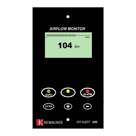
- Page 1 Air Alert 600 FUME HOOD VELOCITY ALARM Operating and Installation Manual Velocity Bar Graph or Alarm Time Line Velocity display fpm or m/sec Control Pushbutton functions AIR ALERT 600 • Digital display • 3 Relay inputs • 3 Relay outputs •...
-
Page 2: Connection Details
Access to the Calibration and Configuration menus is password protected and is factory-set. Default password is 0000. To change the password or other parameters, obtain the alarm communication program from Kewaunee Scientific www.kewaunee.com ). Use a Laptop connected to the Com port and the Upload/Download software to alter password or make other changes. - Page 3 All systems are comprised of the following components: 1 – SM5 In –line Airflow Sensor, 1 – AIR ALERT 600 Alarm unit, 1 – AC power supply If the Sash Alarm System option is included there will also be a sash micro switch or proximity switch.
- Page 4 Condition Messages Displayed on Screen: Sash High –will be displayed when the Sash alarm is enabled and the sash is raised above the max safe working opening. This display will alternate on/off with the velocity reading. Ext Alarm – will be displayed when the external alarm input is activated ( when enabled ) This display will alternate on/off with the velocity reading Air Fail - will be displayed if the airflow is less than the Low air alarm point.
- Page 5 External Connections Input 1 --- volt free relay input configurable for normally closed or normally open relays This input can be configured as: Alarm disable Night set-back External alarm Sash High High / Low Input 2 --- volt free relay input configurable for normally closed or normally open relays This input can be configured as: Alarm disable...
- Page 6 2. The alarm then performs a self-test on the display and all indicators etc (approx. 5 sec) 3. The display show a ‘Welcome note’ – with the Kewaunee name for the rest of the initial 30 sec delay time. During this time the airflow sensor is stabilizing.
- Page 7 5. At the end of the 30 sec delay the unit performs one of two options: a. If the alarm calibration has been previously completed, the unit goes to normal operating mode (Run) b. If the unit has not been calibrated the unit displays: ‘Unit requires set up -- press Enter to access Set up menu’...
- Page 8 Sash High • When the input configured as Sash High is activated • Amber LED on • Sash High – toggles on / off with velocity display • Audible alarm sounds • Audible can be muted via Enter pushbutton -- this silences the alarm and initiates a repeat timer (if configured).
- Page 9 2.1 Quick Start Installation Follow the instructions below for installing and commissioning the unit. :- 1. Fit the alarm to the Fume Hood using the cut-out details provided with the unit see page 12 2. Fit the airflow sensor to the Fume Hood using the cut out and installation details provided --- see page 10 3.
- Page 10 2.2 Calibration Procedure: 1. When using a standard Fume Hood with Vertical Sliding sashes, open the sash to the normal max safe working height for the Low Air sample. 2. For the Higher Air sample close the sash to approx. 50% of the opening used for the Lower Air sample.
- Page 11 3.0 AIR ALERT 600 -- CUTOUT AND ALARM DIMENSIONS Fume hood Side Airfoil ( Front view ) 5 13/16” Sensor Tube Cutout Dimensions 1” diameter 3/16” 3.5” Alarm Panel Dimensions 5” 4 5/8” 8 21/32” 3/16” 2 x Fixing Holes for 3 11/32”...
-
Page 12: Installation Details
4.0 INSTALLATION DETAILS... -
Page 13: Wiring Diagram
5.0 WIRING DIAGRAM 120V / 12V DC 120V Plug – in power adaptor for 120V Relay output 1 socket AIR ALERT 600 Relay output 2 Relay output 3 Flying lead with plug connection for PCB 12 V DC Com port...
Need help?
Do you have a question about the Air Alert 600 and is the answer not in the manual?
Questions and answers