Table of Contents
Advertisement
Advertisement
Table of Contents

Related Manuals for Roda RS-FS60AB


Summary of Contents for Roda RS-FS60AB
- Page 1 AIRCONDITIONER FLOOR STANDING TYPE SERVICE MANUAL RS-FS60AB/RU-60AC3...
-
Page 2: Table Of Contents
2.1 Indoor Unit ..........................3 Outdoor Unit ......................... 4 Refrigerant cycle diagram ....................4 3.1 Heat pump mode ........................4 Wiring diagram ........................5 RS-FS60AB ............................5 Installation details ......................6 5.1 Installation place ........................6 5.2 Installing ..........................8 Refrigerant pipe connection ..................... - Page 3 Operation Modes and Functions ..................26 Other Functions ......................... 29 Characteristic of temperature sensor ................30 Trouble shooting ......................30 10.1 Protective Function ......................30 10.2 Self-diagnosis ........................32 10.3 LEDs for the indication of outdoor trouble ................32 10.4 Troubles and Solutions ......................
-
Page 4: Safety Precautions
1. Safety Precautions 1.1 Precaution To prevent injury to the user or other people and property damage, the following instructions must be followed. Incorrect operation due to ignoring instruction will cause harm or damage. Before service unit, be sure to read this service manual at first. 1.2 Installation For electrical work, contact the dealer, seller, a qualified electrician, or an Authorized service center. -
Page 5: Operational
1.4 Operational Do not expose the skin directly to cool air for long periods of time. (Do not sit in the draft). Do not use the product for special purposes, such as preserving foods, works of art, etc. It is a consumer air conditioner, not a precision refrigerant system. -
Page 6: Dimension
2. Dimension 2.1 Indoor Unit Dimension (mm) (mm) (mm) Mode 1900... -
Page 7: Outdoor Unit
2.2 Outdoor Unit Dimension Mode (mm) (mm) (mm) (mm) (mm) (mm) 1245 1020 3. Refrigerant cycle diagram 3.1 Heat pump mode... -
Page 8: Wiring Diagram
4. Wiring diagram RS-FS60AB Indoor Unit Outdoor Unit... -
Page 9: Installation Details
5. Installation details 5.1 Installation place 5.1.1 Indoor Unit a.Ensure the spaces indicated by arrows from the wall, ceiling, fence or other obstacles. b.There should not be any heat source or steam near the unit. c.There should not be any obstacles blocking the air circulation. d.A place where air circulation in the room is good. - Page 10 b).Select a place that is easy to connect indoor unit's pipe and electric wires. c).Avoid a place where combustible gas may leak or stay. d).Keep it in mind that water may drain out of the outdoor unit while in "Heat" mode. e).Ensure the space around the back and sides and the front of the unit.
-
Page 11: Installing
5.2 Installing 5.2.1 Indoor Unit: 1. Anti-falling; To prevent the indoor unit from falling, you must: a. Pay full attention to the unit because its long outer shape makes it easy to fall; b. Firmly fix the unit to the wall or in the ground to avoid accidental falling. 2. - Page 12 5.2.2 Outdoor Unit: 1. Ship the a/c to the installation place originally packed; 2. Be careful while hanging the unit because the center of gravity of the unit is not centralized; 3. Do not make the angle of inclination more than 45 degrees while shipping;(Avoid horizontal storage) 4.
-
Page 13: Refrigerant Pipe Connection
Dimension Mode (mm) (mm) 5.3 Refrigerant pipe connection 5.3.1 Pipe length and the elevation The correct refrigerant quantity filled in the 5-meter-long pipe of the outdoor unit is marked on the Product Data Plate. If you have to use longer pipe for every meter plus pipe, the refrigerant should be added according to the following calculation. - Page 14 Caution: Capacity is base on standard length and maximum allowance length is base of reliability. Oil trap should be installed per 5-7 meters. 5.3.2 Piping connection 5.3.2.1 Connecting Of Refrigerant Pipe Only the correctly installing of indoor and outdoor unit done, can the refrigerant pipe be connected.
- Page 15 Notes for the bendable pipe a. The bendable pipe should be used on the indoor side; b. Bend angel may not exceed 90 degrees; c. The bend location should be made on the center of the pipe if possible, as for bend radius, the bigger the better;...
- Page 16 Additional Outside diameter Torque tightening torque inch N.cm N.cm Ф12.7 4950 6030 Ф19 9720 11860 5.3.3 Air purging with vacuum pump Air and moisture in the refrigerant system have undesirable effects as below: ● Pressure in the system rises. ● Operating current rises. ●...
- Page 17 Air purging with vacuum pump 1. Completely tighten the flare nuts of the indoor and outdoor units, connect the manifold valve charge. 2. Connect the charge hose connection to the vacuum pump. 3. Fully open the handle Lo of the manifold valve. 4.
- Page 18 8. Fully open the Hi and Lo packed valve. 9. Securely tighten the cap of the packed valve. Gas leak check Soap water method Apply soap water or a liquid neutral detergent on the indoor unit connections or outdoor unit connections by a soft brush to check for leakage of the connecting points of the piping. If bubbles come out, the pipes have leakage.
- Page 19 Connect the charge hose with the push pin to the gas service port. 5. Air purging of the charge hose. Open the low-pressure valve on the charge set slightly to purge air from the charge hose. 6. Set the 2-way valve to the close position. 7.
- Page 20 Procedure: 1. Confirm that both the 2-way and 3-way valves are set to the closed position. 2. Connect the charge set and a charging cylinder to the service port of the 3-way valve. Leave the valve on the charging cylinder closed. 3.
- Page 21 5.3.6 Balance refrigerant of the 2-way, 3-way valves Procedure: 1. Confirm that both the 2-way and 3-way valves are set to the open position. 2. Connect the charge set to the 3-way valve’s service port. Leave the valve on the charge set closed. Connect the charge hose with the push pin to the service port.
- Page 22 5.3.7 Evacuation Procedure: 1. Connect the vacuum pump to the charge set’s centre hose. 2. Evacuation for approximately one hour. Confirm that the gauge needle has moved toward -0.1 Mpa (-76 cmHg) [vacuum of 4 mmHg or less]. 3. Close the valve (Low side) on the charge set, turn off the vacuum pump, and confirm that the gauge needle does not move (approximately 5 minutes after turning off the vacuum pump).
- Page 23 5.3.8 Gas charging Procedure: 1. Connect the charge hose to the charging cylinder. Connect the charge hose which you disconnected from the vacuum pump to the valve at the bottom of the cylinder.If the refrigerant is R410A, make the cylinder bottom up to ensure liquid charge.
-
Page 24: Drain Pipe Of The Indoor Unit
4. Immediately disconnect the charge hose from the 3-way valve’s service port. Stopping partway will allow the refrigerant to be discharged. If the system has been charged with liquid refrigerant while operating the air conditioner, turn off the air conditioner before disconnecting the hose. 5. -
Page 25: Wiring
5.5 Wiring Please refer to the Wiring Diagram. Note: The power supply of the air conditioner is different according to the models. Please refer to the WIRING DIAGRAM pasted on the indoor and outdoor units before wire connection. 5.6 TEST RUN 1. -
Page 26: External View And Display
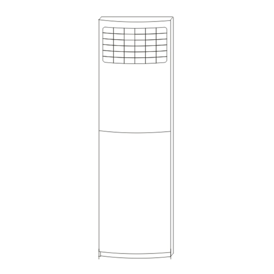
6. External view and display 6.1 PARTS NAMES This unit consists of indoor unit and outdoor unit. Note: All the pictures in this manual are for explanation purpose only. They may be slightly different from the air conditioner you purchased(depend on model). The actual shape shall prevail. -
Page 27: Control Panel
6.2 CONTROL PANEL On/Off button: Power-on and power-off the A/C(Air conditioner) LED indicator :Lights when unit runs normally ,flashes one time per second when the unit is waiting for orders ,flashes two times per second when the unit is sick. Mode select button : Use this button to select among the following 5 modes : Auto :automatically adjust the temperature (17~30℃) -
Page 28: Led
Time adjusting button: ‘Hour’: set the hour of current time ‘Minute’: set the minute of current time Confirm/Cancel button :Push this button to confirm or cancel the timer setting Test Running button :Push this button to make the unit run for an hour of test ,this function is specially designed for maintenance technicians. -
Page 29: Operation Characteristics
7. Operation characteristics Mode Cooling Drying Heating operation operation operation Temperature 17℃~32℃ 17℃~30℃ 17℃~32℃ Room temperature Outdoor temperature 18℃~43℃ -7℃~24℃ 18℃~ 43℃ CAUTION: 1. If air conditioner is used outside of the above conditions, certain safety protection features may come into operation and cause the unit to function abnormally. 2. - Page 30 8.2.2.2 Condition for the compressor and outdoor fan action: (Ts=set temperature, T1=room temperature) Condition Compressor and outdoor fan( High) T s-T1 ≥ 1°C and compressor is off reaches up to over 4 minutes T1-Ts>2°C 8.2.2.3 Indoor Fan Action Auto fan in heating mode Condition Fan speed T s-T1 ≥4°C...
- Page 31 8.2.3.2 Defrosting Action Four-way valve, indoor fan, outdoor fan are shut down. Compressor keeps on. 8.2.3.3 Ending Of Defrosting Condition (meet one of the following is ok): (1)Time of defrosting lasts 10 minutes. (2) Temperature of outdoor coil T3 is up to 20°C. (3) High temperature protection opens(When compressor shuts down), defroste will end, calculate time again.
-
Page 32: Other Functions
8.2.7 Fan Only Mode 8.2.7.1 Under this mode, four-way valve, compressor and outdoor fan are shut down, indoor fan keeps on. 8.2.7.2 High/Med/Low/Auto fan can be switched over through manual control. 8.2.7.3 Under auto mode, the indoor fan is set to be Med. 8.3 Other Functions 8.3.1 LCD display Mode, Set temp.,fan speed, time, timer, etc. -
Page 33: Characteristic Of Temperature Sensor
9. Characteristic of temperature sensor T emp. ℃ Resistance KΩ T emp. ℃ Resistance KΩ T emp. ℃ Resistance KΩ 62.2756 14.6181 4.3874 58.7079 13.918 4.2126 56.3694 13.2631 4.0459 52.2438 12.6431 3.8867 49.3161 12.0561 3.7348 46.5725 11.5 3.5896 10.9731 3.451 41.5878 10.4736 3.3185... - Page 34 10.1.2.2 The operation princi ple is as follows: (T2 = evaporator temperature) Condition Outdoor fan Compressor Room temperature up T2>56°C T2>60°C Room temperature down T2>54°C T2<54°C 10.1.2.3 The restart of the compressor shall execute the delay protection. 10.1.3 Evaporator Protection against low temperature 10.1.3.1 Only available under cooling and dehumidifying status.
-
Page 35: Self-Diagnosis
10.2 Self-diagnosis Codes Contents The temp. sensor is off, or short-circuit. Compressor is over current Outdoor unit protection Compressor is over load The temperature of evaporator coil of indoor unit is too low (when cooling) The temperature of evap io n r d a o to o r r u c o n i i l t o i s f too high (when heating) The temperature of air outlet of indoor unit is too high (when heating) 10.3 LEDs for the indication of outdoor trouble... -
Page 36: Troubles And Solutions
10.4 Troubles and Solutions Before calling for service, please review the following list of common problems and solutions. Problem Possible Cause Solutions Unit Idleness No electric power supply Wait for power recovery Power Switch turned off Turn on the switch Fuse blew Replace the fuse Air flow but poor... - Page 37 The display board may show some types of the unit’ s failures when it happened. Number Display Problems What to do code The temp. sensor is off, or short-circuit. Contact service people Compressor is over current Turn off the unit, wait for a moment and then restart.
- Page 38 NOTE: It is not a failure if : 1. The air smells because of feculent room air. 2. The refrigerant running noise is heard when the unit starts to run; 3. A ‘Pee-pa’ voice is heard when the unit starts or stops running. 4.
Need help?
Do you have a question about the RS-FS60AB and is the answer not in the manual?
Questions and answers