
Summary of Contents for Vectornav VN-100
- Page 1 Embedded Navigation Solutions VN-100 User Manual Firmware v2.1.0.0 Document Revision 2.22 UM001...
- Page 2 Document Status Released VectorNav Technical Documentation In addition to our product-specific technical data sheets, the following manuals are available to assist VectorNav customers in product design and development. VN-100 User Manual: The user manual provides a high-level overview of product specific information for each of our inertial sensors.
-
Page 3: Table Of Contents
1.2 FACTORY CALIBRATION 1.3 OPERATION OVERVIEW 1.4 PACKAGING OPTIONS 1.5 VN-100 PRODUCT CODES 2 Specifications 2.1 VN-100 SURFACE-MOUNT SENSOR (SMD) ELECTRICAL 2.2 VN-100 RUGGED ELECTRICAL 2.3 VN-100 SURFACE-MOUNT SENSOR (SMD) DIMENSIONS 2.4 VN-100 RUGGED DIMENSIONS 2.5 ABSOLUTE MAXIMUM RATINGS 2.6 SENSOR COORDINATE SYSTEM 3 VN-100 Software Architecture 3.1 IMU SUBSYSTEM... - Page 4 5.2 CONFIGURATION REGISTERS 5.3 STATUS REGISTERS 5.4 FACTORY DEFAULTS 5.5 COMMAND PROMPT 6 IMU Subsystem 6.1 IMU MEASUREMENT REGISTERS 6.2 IMU CONFIGURATION REGISTERS 6.3 FACTORY DEFAULTS 6.4 COMMAND PROMPT 7 Attitude Subsystem 7.1 COMMANDS 7.2 MEASUREMENT REGISTERS 8 Hard/Soft Iron Estimator Subsystem 8.1 CONFIGURATION REGISTERS 8.2 STATUS REGISTERS 8.3 FACTORY DEFAULTS...
-
Page 5: Introduction
360 degree range of motion such that there are no limitations on the angles it can compute. However, the VN-100 also has a built-in capability to output yaw, pitch, and roll angles from the VN-100, in which the sensor automatically converts from quaternions to the desired attitude parameter. -
Page 6: Packaging Options
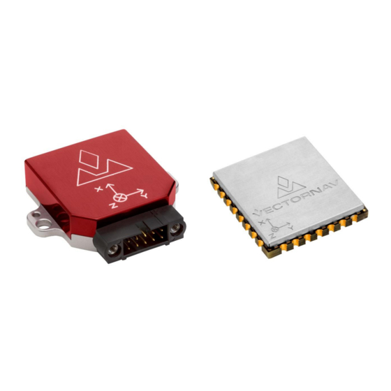
VectorNav has developed a suite of tools called the Vector Processing Engine (VPE™), which are built- into the VN-100 and minimize the effects of these disturbances; however, it is not possible to obtain absolute heading accuracies better than 2 degrees over any extended period of time when relying on magnetometer measurements. - Page 7 1.4.1 Surface-Mount Package For embedded applications, the VN-100 is available in a miniature surface-mount package. Features Small Size: 22 x 24 x 3 mm Single Power Supply: 3.2 to 5.5 V Communication Interface: Serial TTL & SPI ...
-
Page 8: Product Codes
1.4.4 VN-100 Rugged Development Kit The VN-100 Rugged Development Kit includes the VN-100 Rugged sensor along with all of the necessary cabling required for operation. cables are provided in each Development Kit: one custom cable for RS-232 communication and a second custom cable with a built in USB converter. -
Page 9: Specifications
Specifications VN-100 Surface-Mount Sensor (SMD) Electrical Pin assignments (top down view) UM001... - Page 10 VN-100 SMD Pin Assignments Pin Name Type Description Supply Ground. Supply Ground. Supply Ground. Supply Ground. Output Serial UART #2 data output. (sensor) Input Serial UART #2 data input. (sensor) RESTORE Input Normally used to zero (tare) the attitude. To tare, pulse high for at least 1 μs.
- Page 11 VN-100 SMD Power Supply The minimum operating supply voltage is 3.2V and the absolute maximum is 5.5V. 2.1.2 VN-100 SMD Serial (UART) Interface The serial interface on the VN-100 operates with 3V TTL logic. Serial I/O Specifications Specification Typical Input low level voltage -0.5 V...
-
Page 12: Rugged Electrical
VN-100 Rugged Electrical VN-100 Rugged Pin Assignments Pin Name Description +4.5V to +5.5V RS-232 voltage levels data output from the sensor. (Serial UART #1) RS-232 voltage levels data input to the sensor. (Serial UART #1) SYNC_OUT Output signal used for synchronization purposes. Software configurable to pulse when ADC, IMU, or attitude measurements are available. - Page 13 2.2.1 VN-100 Rugged Power Supply The power supply input for the VN-100 Rugged is 4.5 to 5.5 V DC. 2.2.2 VN-100 Rugged Serial UART Interface Serial I/O Specifications Specification Typical Input low level voltage -25 V Input high level voltage...
-
Page 14: Surface-Mount Sensor (Smd) Dimensions
VN-100 Surface-Mount Sensor (SMD) Dimensions * Measurements are in inches VN-100 Rugged Dimensions UM001... -
Page 15: Absolute Maximum Ratings
Rugged Connector Type The main connector used on the VN-100 Rugged is a 10-pin Harwin M80-5001042. The mating connector used on the cable assemblies provided by VectorNav for use with the VN-100 Rugged is a Harwin M80- 4861005. Absolute Maximum Ratings... - Page 16 2.6.2 North-East-Down Frame The VN-100 velocity estimates can be output in the North-East-Down (NED) coordinate frame defined as follows (N Right-handed, Cartesian, non-inertial, geodetic frame with origin located at the surface of Earth (WGS84 ellipsoid); Positive X-axis points towards North, tangent to WGS84 ellipsoid;...
-
Page 17: Software Architecture
VN-100 Software Architecture The software architecture internal to the VN-100 includes four separate subsystems. These subsystems are the IMU, the NavState, the NavFilter, and the Communication Interface. The high-level functions performed by these subsystems are outlined below. This chapter describes these functions performed by these subsystems in more detail and describes which of the various measurement outputs originate from each of these corresponding subsystems. - Page 18 3.1.5 Factory Calibration Each VN-100 sensor is tested at the factory at multiple known angular rates, accelerations, and magnetic field strengths to determine each sensor’s unique bias, scale factor, axis alignment, and temperature dependence. The calibration coefficients required to remove these unwanted errors are permanently stored in flash memory on each sensor.
-
Page 19: User Calibration
3.1.6 User Calibration The VN-100 provides the user with the ability to apply a separate user calibration to remove additional bias, scale factor, and axis misalignments. The user calibration is applied after the factory calibration, and can be used to optionally fine tune the calibration for each of the individual sensors. The user calibration is optional and in most cases not required for normal operation. -
Page 20: Navstate Subsystem
The NavState guarantees the output of new updated state information at a rate fixed to the IMU Rate with very low latency and output jitter. The NavState also provides the ability for the VN-100 to output estimated states at rates faster than the rate of the onboard Kalman filters, which may be affected by system load and input measurements availability. - Page 21 Earth’s core. By default the world magnetic model on the VN-100 is turned off, allowing the user to directly set the reference magnetic field strength. Alternatively the world magnetic model can be manually used to calculate the magnetic field strength for a given latitude, longitude, altitude, and date which is then subsequently used as the fixed magnetic field reference strength.
-
Page 22: Vector Processing Engine
Gravity Model (EGM96), which consist of a spherical-harmonic expansion of the Earth’s geopotential. By default the world gravity model on the VN-100 is turned off, allowing the user to directly set the reference gravity vector. Control of the world gravity model is performed using the Reference Vector Configuration Register. - Page 23 VPE will maintain a stable heading estimate. Over long periods of time under conditions where the magnetic field direction changes frequently, in Relative Heading mode it is possible for the VN-100 to accumulate some error in its reported heading relative to true North. In this mode the VPE will not attempt to correct for this accumulated heading error.
- Page 24 which minimizes the effect of gyro drift while maintaining a stable and accurate pitch and roll solution. Since the Relative Heading mode assumes that other magnetic disturbances can be present which are indistinguishable from the Earth's field, Relative Heading mode cannot always ensure that the calculated heading is always referenced to Earth's magnetic north.
- Page 25 Indoor Heading Mode Disadvantages Measurement repeatability may be worse than Relative Mode during periods when the VPE corrects for known errors in absolute heading. Overview of Heading Modes A summary of the different types of disturbances handled by each magnetic mode is summarized in the table below.
-
Page 26: Communication Interface
The SPI interface consists of a standard 4-wire synchronous serial data link which is capable of high data rates up to 16 Mbps. The VN-100 operates as slave on the bus enabled by the master using the slave select (SPI_CS) line. See the Basic Communication chapter for more information on the operation of the SPI interface. -
Page 27: Communication Protocol
System Error Codes In the event of an error, the VN-100 will output $VNERR, followed by an error code. The possible error codes are listed in the table below with a description of the error. - Page 28 Description Hard Fault If this error occurs, then the firmware on the VN-100 has experienced a hard fault exception. To recover from this error the processor will force a restart, and a discontinuity will occur in the serial output. The processor will restart within 50 ms of a hard fault error.
-
Page 29: Checksum / Crc
Checksum / CRC The serial interface provides the option for either an 8-bit checksum or a 16-bit CRC. In the event neither the checksum nor the CRC is needed, both can be turned off by the user. Refer to the Communication Protocol Control Register for details on disabling the checksum/CRC. - Page 30 For cases where the 8-bit checksum doesn't provide enough error detection, a full 16-bit CRC is available. The VN-100 uses the CRC16-CCITT algorithm. The resultant CRC is a 16-bit number and is represented in the command as four hexadecimal characters. The C function snippet below calculates the correct CRC.
-
Page 31: User Configurable Binary Output Messages
(IMU Rate). Available Output Types All real-time measurements either measured or estimated by the VN-100 are available using the user output messages. The different output types are organized into 6 separate output groups. The first group is a combination of the most common outputs from the remaining groups. The other groups are shown below. - Page 32 Output Group 5 Attitude Group Output group 4, 6, & 7 are not used on the VN-100. The bits for these unused output groups must be set to zero. Groups 8-14 are not used, however they are reserved for use in future firmware versions.
- Page 33 4.2.3 Setup the Configuration Register Once you have determined the desired outputs for your output messages, you will need to configure the User Output Message Configuration Registers (Register 75 – 77). These registers are described in detail under the Binary Output Register 1-3 in the System subsystem section, however for reference the format of the register is shown below.
- Page 34 AngularRate For this example we will assume that the data will be polled using serial port 2 at 50 Hz. To configure this output message you would send the following command to the VN-100. $VNWRG,75,2,16,01,0029*XX Now let’s dissect this command to see what is actually being set:...
- Page 35 MagNed Also assume that you want the message to stream at 50 Hz over serial port 1. To configure this output message you would send the following command to the VN-100. $VNWRG,75,1,16,15,0001,000C,0014*XX Now let’s dissect this command to see what is actually being set:...
-
Page 36: Serial Output Message Format
Serial Output Message Format The binary output message packets on the serial interface consist of a simple message header, payload, and a 16-bit CRC. An example packet is shown below for reference. The header is variable length depending upon the number of groups active in the message. Header Payload Sync... - Page 37 4.3.3 Group Fields The Group Field parameter consists of a series of one or more 16-bit words per selected output group which are used to identify the selected output fields for that group. The first series of one or more words corresponds to the fields for the first selected group, followed by a series of word(s) for the next selected group, and so on.
- Page 38 If you want to develop a more generic parser that can handle all available data output types supported by the VN-100, the easiest approach is to use a table lookup. Below is a table with the payload size (in bytes) for all available output types.
- Page 39 Example Code // 2D array to determine the payload length for a binary output packet. The first // index of the array is the group number, and the second index // is the group field index. Both indices are assumed to be zero based. const unsigned char groupLen[7][16] = 12, 16, 12, 24, 12, 12, 24, 20, 28, 2,...
- Page 40 Example Case 2 For the second example case we will assume that both binary group 1 and 3 are active. In binary group 1, the Ypr output is selected, and in binary group 3, the Temp output is selected. Header Field Sync Group...
-
Page 41: Binary Group 1 - Common Outputs
Binary Group 1 – Common Outputs Binary group 1 contains a wide assortment of commonly used data required for most applications. All of the outputs found in group 1 are also present in the other groups. In this sense, group 1 is a subset of commonly used outputs from the other groups. - Page 42 4.4.3 YawPitchRoll The estimated attitude Yaw, Pitch, and Roll angles measured in degrees. The attitude is given as a 3,2,1 Euler angle sequence describing the body frame with respect to the local North East Down (NED) frame. This field is equivalent to the YawPitchRoll field in group 5. YawPitchRoll pitch roll...
- Page 43 rate and acceleration measurements straight from the IMU. The measurements have not been corrected for bias offset by the onboard Kalman filter. These are equivalent to the UncompAccel and UncompGyro fields in group 3. accel[0] accel[1] accel[2] rate[0] rate[1] rate[2] Byte Offset Type...
- Page 44 4.4.10 SyncInCnt The number of SyncIn trigger events that have occurred. This field is equivalent to the SyncInCnt field in group 2. SyncInCnt Byte Offset Type UM001...
-
Page 45: Binary Group 2 - Time Outputs
Binary Group 2 – Time Outputs Binary group 2 provides all timing and event counter related outputs. Some of these outputs (such as the TimeGps, TimePps, and TimeUtc), require either that the internal GPS to be enabled, or an external GPS must be present. -
Page 46: Binary Group 3 - Imu Outputs
Binary Group 3 – IMU Outputs Binary group 3 provides all outputs which are dependent upon the measurements collected from the onboard IMU, or an external IMU (if enabled). Binary Group 3 Name Bit Offset Description ImuStatus Reserved for future use. UncompMag Uncompensated magnetic measurement. - Page 47 4.6.4 UncompGyro The IMU angular rate measured in units of rad/s, given in the body frame. This measurement is compensated by the static calibration (individual factory calibration stored in flash), however it is not compensated by any dynamic calibration such as the bias compensation from the onboard AHRS/INS Kalman filters.
- Page 48 4.6.8 DeltaV The delta velocity (dvel) is the delta velocity incurred due to motion, since the last time the values were output by the device. The delta velocities are calculated based upon the onboard conning and sculling integration performed onboard the sensor at the IMU sampling rate (nominally 800Hz). The integration for the delta velocities are reset each time the values are either polled or sent out due to a scheduled asynchronous ASCII or binary output.
-
Page 49: Binary Group 5 - Attitude Outputs
Binary Group 5 – Attitude Outputs Binary group 5 provides all estimated outputs which are dependent upon the estimated attitude solution. The attitude will be derived from either the AHRS or the INS, depending upon which filter is currently active and tracking. All of the fields in this group will only be valid if the AHRS/INS filter is currently enabled and tracking. - Page 50 Table 1 - AttitudeQuality Field Value Description Excellent Good Not tracking 4.7.2 YawPitchRoll The estimated attitude Yaw, Pitch, and Roll angles measured in degrees. The attitude is given as a 3,2,1 Euler angle sequence describing the body frame with respect to the local North East Down (NED) frame. YawPitchRoll pitch roll...
- Page 51 stored in flash), and the dynamic calibration such as the user or onboard Hard/Soft Iron compensation registers. MagNed mag[0] mag[1] mag[2] Byte Offset Type float float float 4.7.6 AccelNed The estimated acceleration (with gravity) reported in m/s^2, given in the North East Down (NED) frame. The acceleration measurement has been bias compensated by the onboard INS filter.
- Page 52 4.7.8 LinearAccelNed The estimated linear acceleration (without gravity) reported in m/s^2, and given in the North East Down (NED) frame. This measurement is attitude dependent as the attitude solution is used to map the measurement from the body frame into the inertial (NED) frame. This acceleration measurement has been bias compensated by the onboard INS filter, and the gravity component has been removed using the current gravity reference vector estimate.
-
Page 53: System Module
Write Register Command This command is used to write data values to a specified register on the VN-100 module. The ID of the register to be written to is the first parameter. This is followed by the data values specific to that register. - Page 54 If no values are stored in non-volatile memory, the device will default to factory settings. Also upon reset the VN-100 will re-initialize its Kalman filter, thus the filter will take a few seconds to completely converge on the correct attitude and correct for gyro bias.
- Page 55 1, the VN-100 will enter into firmware reprogramming mode. The easiest method of updating firmware is to use one of the VectorNav Firmware Update Tools. If you wish however to incorporate the ability to update the firmware into your own system, the protocol and procedure for updating the firmware is outlined in the AN013 Firmware Update Protocol application note.
- Page 56 This command is useful when you want to send configuration commands to the VN-100, but do not want to deal with the additional overhead of having to parse a constant stream of asynchronous output messages while waiting for the response to your configuration commands.
-
Page 57: Configuration Registers
Configuration Registers 5.2.1 User Tag Register User Tag Register ID : Access : Read / Write Comment : User assigned tag register. Any values can be assigned to this register. They will be stored to flash upon issuing a write settings command. Size (Bytes): Example Response: $VNRRG,00,SENSOR_A14*52... - Page 58 5.2.2 Model Number Register Model Number Register ID : Access : Read Only Comment : Model Number Size (Bytes): Example Response: $VNRRG,01,VN-310*58 Offset Name Format Unit Description Product char Product name. Max 24 characters. Name UM001...
- Page 59 5.2.3 Hardware Revision Register Register ID : Access : Read Only Comment : Hardware revision. Size (Bytes): Example Response: $VNRRG,02,1*6C Offset Name Format Unit Description Revision uint32 Hardware revision. UM001...
- Page 60 5.2.4 Serial Number Register Serial Number Register ID : Access : Read Only Comment : Serial Number Size (Bytes): Example Response: $VNRRG,03,0100011981*5D Offset Name Format Unit Description SerialNum uint32 Serial Number (32-bit unsigned integer) UM001...
- Page 61 5.2.5 Firmware Version Register Firmware Version Register Register ID : Access : Read Only Comment : Firmware version. Size (Bytes): Example Response: $VNRRG,04,0.4.0.0*71 Offset Name Format Unit Description Major uint8 Major release version of firmware. Version Minor uint8 Minor release version of firmware Version Feature uint8...
- Page 62 The response to this register will include the serial port parameter if the optional parameter is provided. If the second parameter is not provided then the response will not include this parameter. Upon receiving a baud rate change request, the VN-100 will send the response prior to changing the baud rate. UM001...
- Page 63 5.2.7 Async Data Output Type Register Asynchronous Data Output Type Register ID : Access : Read / Write Comment : Asynchronous data output type. Size (Bytes): Example Command: $VNWRG,06,0*6C Offset Name Format Unit Description ADOR uint32 Output register. Serial Port uint8 Optional.
- Page 64 Asynchronous Solution Output Settings Setting Asynchronous Solution Output Type Header Asynchronous output turned off Yaw, Pitch, Roll VNYPR Quaternion VNQTN Quaternion, Magnetic, Acceleration and Angular Rates VNQMR Directional Cosine Orientation Matrix VNDCM Magnetic Measurements VNMAG Acceleration Measurements VNACC Angular Rate Measurements VNGYR Magnetic, Acceleration, and Angular Rate Measurements VNMAR...
- Page 65 5.2.8 Async Data Output Frequency Register Asynchronous Data Output Frequency Register ID : Access : Read / Write Comment : Asynchronous data output frequency. Size (Bytes): Example Command: $VNWRG,07,40*59 Offset Name Format Unit Description ADOF uint32 Output frequency. Serial Port uint8 Optional.
- Page 66 SyncIn event. The relationship between the SyncIn event and a SyncIn trigger is defined by the SyncInEdge and SyncInSkipFactor parameters. If set to ASYNC then the VN-100 will output asynchronous serial messages upon each trigger event.
- Page 67 SyncInEdge The SyncInEdge register controls the type of edge the signal is set to trigger on. The factory default state is to trigger on a rising edge. SyncInEdge Mode Value Description Trigger on rising edge Trigger on falling edge SyncInSkipFactor The SyncInSkipFactor defines how many times trigger edges defined by SyncInEdge should occur prior to triggering a SyncIn event.
- Page 68 5.2.10 Communication Protocol Control Communication Protocol Control Read / Register ID : Access : Write Comment : Contains parameters that controls the communication protocol used by the sensor. Size (Bytes): Example Response: $VNRRG,30,0,0,0,0,1,0,1*6C Offset Name Format Unit Description Provides the ability to append a counter or time to the end SerialCount uint8 of the serial asynchronous messages.
- Page 69 Serial Count The SerialCount field provides a means of appending a time or counter to the end of all asynchronous communication messages transmitted on the serial interface. The values for each of these counters come directly from the Synchronization Status Register in the System subsystem. With the SerialCount field set to OFF a typical serial asynchronous message would appear as the following: $VNYPR,+010.071,+000.278,-002.026*60 With the SerialCount field set to one of the non-zero values the same asynchronous message would...
- Page 70 INS Status SerialChecksum This field controls the type of checksum used for the serial communications. Normally the VN-100 uses an 8-bit checksum identical to the type used for normal GPS NMEA packets. This form of checksum however offers only a limited means of error checking. As an alternative a full 16-bit CRC (CRC16-CCITT with polynomial = 0x07) is also offered.
- Page 71 ErrorMode This field controls the type of action taken by the VN-100 when an error event occurs. If the send error mode is enabled then a message similar to the one shown below will be sent on the serial bus when an error event occurs.
- Page 72 5.2.11 Binary Output Register 1 Binary Output Register 1 Register ID : Access : Read / Write This register allows the user to construct a custom binary output message that contains a Comment : collection of desired estimated states and sensor measurements. Size (Bytes): 6-22 Example Response:...
- Page 73 5.2.12 Binary Output Register 2 Binary Output Register 2 Register ID : Access : Read / Write This register allows the user to construct a custom binary output message that contains a Comment : collection of desired estimated states and sensor measurements. Size (Bytes): 6-22 Example Response:...
- Page 74 5.2.13 Binary Output Register 3 Binary Output Register 3 Register ID : Access : Read / Write This register allows the user to construct a custom binary output message that contains a Comment : collection of desired estimated states and sensor measurements. Size (Bytes): 6-22 Example Response:...
-
Page 75: Status Registers
Status Registers 5.3.1 Synchronization Status Synchronization Status Register ID : Access : Read / Write Comment : Contains status parameters that pertaining to the communication synchronization features. Size (Bytes): Example $VNRRG,33,2552498,0,0*6A Response: Offset Name Format Unit Description Keeps track of the number of times that the SyncIn trigger even has occured. -
Page 76: Factory Defaults
Factory Defaults Settings Name Default Factory Value User Tag NULL (Empty string) Serial Baud Rate 115200 Async Data Output Frequency 40 Hz Async Data Output Type INS_LLA Synchronization Control 3,0,0,0,6,1,0,100000000,0 Communication Protocol Control 0,0,0,0,1,0,1 Binary Output Register 1 0, 0, 0 Binary Output Register 2 0, 0, 0 Binary Output Register 3... -
Page 77: Command Prompt
Command Prompt The command prompt provides a fast and simple means of configuring and monitoring the status of the sensor by typing commands to the unit using the serial port. 5.5.1 List Available Commands Commands for the System subsystem can be accessed by typing in ‘system’ at the command prompt. To view all available commands, type ‘system ?’. - Page 78 Current Serial 1 TX Bandwidth Usage : 00.0 Current Serial 2 TX Bandwidth Usage : 49.3 Max Serial 1 TX Bandwidth Usage : 49.3 Max Serial 2 TX Bandwidth Usage : 50.5 Min Serial 1 TX Bandwidth Usage : 00.0 Min Serial 2 TX Bandwidth Usage : 48.1 -------------------------------------------------------------------------------- 5.5.4...
-
Page 79: Imu Subsystem
IMU Subsystem IMU Measurement Registers 6.1.1 IMU Measurements This register provides direct access to the calibrated magnetometer, accelerometer, gyro, barometric pressure, and temperature measurements available from the onboard IMU. IMU Measurements Register ID : Async Header : Access : Read Only Comment : Provides the calibrated IMU measurements including barometric pressure. - Page 80 6.1.2 Delta Theta and Delta Velocity Delta Theta and Delta Velocity Register ID : Async Header: Access : Read Comment : This register contains the output values of the onboard coning and sculling algorithm. Size (Bytes): Example Response: $VNRRG,80,+0.665016,-000.119,-000.409,-000.025,+000.011,-000.084,-006.702*6A Offset Name Format Unit...
-
Page 81: Imu Configuration Registers
IMU Configuration Registers 6.2.1 Magnetometer Compensation Magnetometer Compensation Register ID : Access: Read / Write Comment : Allows the magnetometer to be compensated for hard/soft iron effects. Size (Bytes): Example Command: $VNRRG,23,1,0,0,0,1,0,0,0,1,0,0,0*73 Offset Name Format Unit Description C[0,0] float C[0,1] float C[0,2] float... - Page 82 6.2.2 Acceleration Compensation Accelerometer Compensation Register ID : Access : Read / Write Allows the accelerometer to be further compensated for scale factor, misalignment, and Comment : bias errors. Size (Bytes): Example Command: $VNRRG,25,1,0,0,0,1,0,0,0,1,0,0,0*75 Offset Name Format Unit Description C[0,0] float C[0,1] float...
- Page 83 6.2.3 Gyro Compensation Gyro Compensation Register ID : Access : Read / Write Comment : Allows the gyro to be further compensated for scale factor, misalignment, and bias errors. Size (Bytes): Example Command: $VNRRG,84,1,0,0,0,1,0,0,0,1,0,0,0*7E Offset Name Format Unit Description C[0,0] float C[0,1] float...
- Page 84 This register contains a transformation matrix that allows for the transformation of measured acceleration, magnetic, and angular rates from the body frame of the VN-100 to any other arbitrary frame of reference. The use of this register allows for the sensor to be placed in any arbitrary orientation with respect to the user’s desired body coordinate frame.
- Page 85 6.2.5 IMU Filtering Configuration IMU Filtering Configuration Register ID : Access : Read / Write Comment : Controls the level of filtering performed on the raw IMU measurements. Size (Bytes): Example Response: $VNRRG,85,0,5,5,5,0,0,3,3,3,0*78 Offset Name Format Unit Description MagWindowSize uint16 Number of previous measurements averaged for magnetic measurements.
- Page 86 6.2.6 Delta Theta and Delta Velocity Configuration Delta Theta and Delta Velocity Configuration Register ID : Access : Read / Write Comment : This register contains configuration options for the internal coning/sculling calculations Size (Bytes): Example Response: $VNRRG,82,0,0,0,0,0*65 Offset Name Format Unit Description...
- Page 87 AccelCompensation The AccelCompensation register setting selects the compensation to be applied to the acceleration measurements before integration. If bias compensation is selected, the onboard Kalman filter’s real-time estimate of the accel biases will be used to compensate the IMU measurements before integration. The factory default state is to integrate the uncompensated acceleration from the IMU.
-
Page 88: Factory Defaults
Factory Defaults Settings Name Default Factory Value Magnetometer Compensation 1,0,0,0,1,0,0,0,1,0,0,0 Accelerometer Compensation 1,0,0,0,1,0,0,0,1,0,0,0 Gyro Compensation 1,0,0,0,1,0,0,0,1,0,0,0 Reference Frame Rotation 1,0,0,0,1,0,0,0,1 IMU Filtering Configuration 0,4,4,4,0,0,3,3,3,0 Delta Theta and Delta Velocity 0,0,0,0,0 Configuration UM001... -
Page 89: Command Prompt
Command Prompt The command prompt provides a fast and simple means of configuring and monitoring the status of the sensor by typing commands to the unit using the serial port. 6.4.1 List Available Commands Commands for the System subsystem can be accessed by typing in ‘imu’ at the command prompt. To view all available commands, type ‘imu ?’. - Page 90 6.4.3 IMU Meas imu meas ------------------------------ Imu Measurement ------------------------------- Current Sensor Measurements: Mag X : -000.866 [Gauss] Mag Y : +001.016 [Gauss] Mag Z : +002.365 [Gauss] Acel X : +004.178 [m/s] Acel Y : -000.637 [m/s] Acel Z : -008.927 [m/s] Gyro X : -000.417 [deg/s] Gyro Y...
-
Page 91: Attitude Subsystem
System subsystem to save the state of this register to flash memory. Once saved the VN-100 will use these bias estimates as the initial state at startup. -
Page 92: Measurement Registers
UART Command $VNSGB*XX UART Response $VNSGB*XX SPI Command (8 bytes) 0C 00 00 00 (shown as hex) SPI Response (8 bytes) 00 0C 00 00 (shown as hex) Measurement Registers 7.2.1 Yaw Pitch Roll Yaw, Pitch, and Roll Register ID : Async Header : Access : Read Only... - Page 93 7.2.2 Attitude Quaternion Quaternion Register ID : Async Header : Access : Read Only Comment : Attitude solution as a quaternion. Size (Bytes): Example Response: $VNRRG,9,-0.017386,-0.000303,+0.055490,+0.998308*4F Offset Name Format Unit Description Quat[0] float Calculated attitude as quaternion. Quat[1] float Calculated attitude as quaternion. Quat[2] float Calculated attitude as quaternion.
- Page 94 7.2.3 Yaw, Pitch, Roll, Magnetic, Acceleration, and Angular Rates Yaw, Pitch, Roll, Magnetic, Acceleration, and Angular Rates Register ID : Async Header : Access : Read Only Comment : Attitude solution, magnetic, acceleration, and compensated angular rates. Size (Bytes): Example Response: $VNRRG,27,+006.380,+000.023,-001.953,+1.0640,- 0.2531,+3.0614,+00.005,+00.344,-09.758,-0.001222,-0.000450,-0.001218*4F Offset...
- Page 95 7.2.4 Quaternion, Magnetic, Acceleration and Angular Rates Quaternion, Magnetic, Acceleration, and Angular Rates Register ID : Async Header : Access : Read Only Comment : Attitude solution, magnetic, acceleration, and compensated angular rates. Size (Bytes): Example Response: $VNRRG,15,-0.017057,-0.000767,+0.056534,+0.998255,+1.0670,-0.2568,+3.0696,- 00.019,+00.320,-09.802,-0.002801,-0.001186,-0.001582*65 Offset Name Format Unit...
- Page 96 7.2.5 Magnetic Measurements Magnetic Measurements Register ID : Async Header : Access : Read Only Comment : Magnetometer measurements. Size (Bytes): Example Response: $VNRRG,17,+1.0647,-0.2498,+3.0628*66 Offset Name Format Unit Description MagX float Gauss Compensated magnetometer measurement in x-axis. MagY float Gauss Compensated magnetometer measurement in y-axis.
- Page 97 7.2.6 Acceleration Measurements Acceleration Measurements Register ID : Async Header : Access : Read Only Comment : Acceleration measurements. Size (Bytes): Example Response: $VNRRG,18,+00.013,+00.354,-09.801*65 Offset Name Format Unit Description AccelX float Compensated accelerometer measurement in x-axis. AccelY float Compensated accelerometer measurement in y-axis. AccelZ float Compensated accelerometer measurement in z-axis.
- Page 98 7.2.7 Angular Rate Measurements Angular Rate Measurements Register ID : Async Header : Access : Read Only Comment : Compensated angular rates. Size (Bytes): Example Response: $VNRRG,19,+0.002112,-0.000362,-0.000876*6C Offset Name Format Unit Description GyroX float rad/s Compensated angular rate in x-axis. GyroY float rad/s...
- Page 99 7.2.8 Magnetic, Acceleration and Angular Rates Magnetic, Acceleration, and Angular Rates Register ID : Async Header : Access : Read Only Comment : Magnetic, acceleration, and compensated angular rates. Size (Bytes): Example Response: $VNRRG,20,+1.0684,-0.2578,+3.0649,-00.005,+00.341,-09.780,-0.000963,+0.000840,- 0.000466*64 Offset Name Format Unit Description MagX float Gauss...
-
Page 100: Hard/Soft Iron Estimator Subsystem
Hard/Soft Iron Estimator Subsystem Configuration Registers 8.1.1 Magnetometer Calibration Control Magnetometer Calibration Control Register ID : Access : Read / Write Comment : Controls the magnetometer real-time calibration algorithm. Size (Bytes): Example Response: $VNRRG,44,1,2,5*69 Offset Name Format Unit Description HSIMode uint8 Controls the mode of operation for the onboard real-time magnetometer hard/soft iron compensation algorithm. -
Page 101: Status Registers
Status Registers 8.2.1 Calculated Magnetometer Calibration Calculated Magnetometer Calibration Register ID : Access : Read Only Comment : Calculated magnetometer calibration values. Size (Bytes): Example Response: $VNRRG,46,1,0,0,0,1,0,0,0,1,0,0,0*70 Offset Name Format Unit Description C[0,0] float C[0,1] float C[0,2] float C[1,0] float C[1,1] float C[1,2]... -
Page 102: Factory Defaults
Factory Defaults Settings Name Default Factory Value Magnetometer Calibration Control 1,3,5 UM001... -
Page 103: Command Prompt
Command Prompt The command prompt provides a fast and simple means of configuring and monitoring the status of the sensor by typing commands to the unit using the serial port. 8.4.1 List Available Commands Commands for the System subsystem can be accessed by typing in ‘hsi’ at the command prompt. To view all available commands, type ‘hsi ?’. - Page 104 8.4.3 PlotInput hsi plotinput --------------------- HSI Estimator Magnetic Input Plot ---------------------- Uncalibrated XY +-------------------+-------------------+-------------------+-------------------+ **** * |* * *** ** * * * * ** * * +---------***-------+-----------*-------*----*--*-----*-----+----------*--------+ * ** * * * * * * +---*-*-*-----------+---*---------------+--------*-----*----+*------*-------*---+ ** | ** * ** * ** * +--------**--------*+-------------------+-------------------+-----***-----------+...
- Page 105 8.4.4 PlotOutput hsi plotoutput --------------------- HSI Estimator Magnetic Output Plot --------------------- Calibrated XY +-------------------+-------------------+-------------------+-------------------+ *** * * * * * *| * * * *** *** * *** ** ** +-----------------*-+--*------*---------+-------------------+-------------------+ * | ** * * ** | +----------*----**--+-------------------+---*---*---------*-+---------------**--+ *** * * **** |* ** +-----------***--*--+--*----------------+----------*--------+-------------------+...
-
Page 106: Velocity Aiding
Velocity Aiding Velocity aiding provides a method to increase performance of an AHRS sensor for applications where the sensor is subjected to constant accelerations. Overview AHRS Fundamentals An Attitude Heading Reference System (AHRS) is a sensor system that estimates the attitude of a vehicle based upon the combined measurements provided by a 3-axis gyroscope, accelerometer, and magnetometer. - Page 107 When an aircraft is in a banked turn the accelerometer will measure gravity plus this centripetal acceleration which will result in a measurement vector that acts perpendicular to the wings of the aircraft as shown in the above figure. This will result in the AHRS estimating a roll angle of zero while the aircraft is in fact in a banked turn and thus has a significant actual roll angle relative to the horizon.
- Page 108 actual attitude which is derived from the flight simulator. Moving from left to right are three separate types of attitude estimators shown in order based upon the accuracy of their derived solution. The most accurate solution is proved by the Inertial Navigation System (INS). This type of estimator incorporates the position and velocity measurements from a GPS along with the accelerometer, and gyroscope in an optimal fashion to simultaneously estimate attitude and the position and velocity of the vehicle.
- Page 109 Velocity Measurement Rate The performance of the velocity compensation will be affected by both the accuracy of the velocity measurements and the rate at which they are applied. To ensure adequate performance the velocity should be provided at a rate higher than 1Hz. Best performance will be achieved with update rates of 10Hz or higher.
-
Page 110: Configuration Registers
Configuration Registers 9.2.1 Velocity Compensation Control Velocity Compensation Control Register ID : Access : Read / Write Comment : Provides control over the velocity compensation feature for the attitude filter. Size (Bytes): Example Response: $VNRRG,51,1,0.1,0.01*5A Offset Name Format Unit Description Mode uint8 Selects the type of velocity compensation performed by... -
Page 111: Status Registers
Status Registers 9.3.1 Velocity Compensation Status INTERNAL REGISTER This register is not listed in the public User Manual. It is not recommended to supply this register to customers unless there is a specific reason to do so. Velocity Compensation Status Register ID : Access : Read... -
Page 112: Input Measurements
Velocity in the Z-Axis measured in the sensor frame. For Mode 1 (body measurement mode) the VN-100 will compute the vector length of the provided 3D velocity vector and use this for velocity compensation. If you have a scalar measurement you can set only the X-axis and set the Y &... -
Page 113: Factory Defaults
Factory Defaults Settings Name Default Factory Value Velocity Compensation Control 1,0.1,0.01 UM001... - Page 114 No license to any intellectual property, expressed or implied, is granted under this document. If any part of this document refers to any third party products or services it shall not be deemed a license grant by VectorNav for the...
Need help?
Do you have a question about the VN-100 and is the answer not in the manual?
Questions and answers