Table of Contents
Advertisement
Quick Links
Advertisement
Table of Contents

Related Manuals for ZMM Haskovo PELLETHERM V.4 LT SERIES

Summary of Contents for ZMM Haskovo PELLETHERM V.4 LT SERIES
- Page 1 MANUAL FOR INSTALLATION, OPERATION AND MAINTENANCE OF A SYSTEM, CONSISTING OF A HOT WATER PELLET BOILER FROM SERIES “PELLETHERM V.4 LT” AND AN AUTOMATED PELLET BURNER FROM SERIES “GP xx sc” http:// www.greenecotherm.eu EN 01 Pelletherm V.4 LT...
- Page 2 Manufacturer ZMM Haskovo PLC Address 67 Saedinenie blvd., 6300 Haskovo, Bulgaria Phone number +359 800 15 145 +359 38 603 070 e-mail sales@ecotherm.bg home page www.greenecotherm.eu The manufacture company thanks you for your choice. The manufacture company submits this manual to help the team that will install, adjust and service the system - hot water pellet boiler and pellet burner, as well as to the customer that will operate it.
-
Page 3: Table Of Contents
CONTENT page. USER SAFETY INFORMATION..........................4 SYSTEM ADVANTAGES: A HOT WATER PELLET BOILER FROM SERIES “PELLETHERM V.4 LT” AND AN AUTOMATED PELLET BURNER FROM SERIES “GP XX SC”....................5 DESCRIPTION OF THE SYSTEM: A HOT WATER PELLET BOILER FROM SERIES “PELLETHERM V.4 LT” AND AN AUTOMATED PELLET BURNER FROM SERIES “GP XX SC”. -
Page 4: User Safety Information
USER SAFETY INFORMATION. The manual for installation, operation and maintenance of the system, consisting of a hot water pellet boiler from series “Pelletherm V.4 LT” and an automated pellet burner from series “GP xx sc”, is designated for end users and authorized servicing specialists. The user must know that: All activities regarding installation of the boiler and the pellet burner should be performed only by an authorized installers, which have acquired legal rights by the... -
Page 5: System Advantages: A Hot Water Pellet Boiler From Series "Pelletherm V.4 Lt" And An Automated Pellet Burner From Series "Gp Xx Sc
2. SYSTEM ADVANTAGES: A HOT WATER PELLET BOILER FROM SERIES “PELLETHERM V.4 LT” AND AN AUTOMATED PELLET BURNER FROM SERIES “GP XX SC”. Type designation of boiler series: “Pelletherm V.4 LT” Example Pelletherm Boiler trade name Nominal heating output*, kW Boiler version Boiler model * Similar to other models of hot water boilers Pelletherm 25 V.4 LT and Pelletherm 30 V.4 LT. - Page 6 Advantages of the system: The system is designated for biomass utilization, which makes it ecologically clean and does not contribute to environment polluting and to planet’s global warming; The system: a hot water pellet boiler from series “Pelletherm V.4 LT” and a pellet burner from series “GP xx sc”...
-
Page 7: Description Of The System: A Hot Water Pellet Boiler From Series "Pelletherm V.4 Lt" And An Automated Pellet Burner From Series "Gp Xx Sc
3. DESCRIPTION OF THE SYSTEM: A HOT WATER PELLET BOILER FROM SERIES “PELLETHERM V.4 LT” AND AN AUTOMATED PELLET BURNER FROM SERIES “GP XX SC”. 3.1. CONSTRUCTION DESCRIPTION OF STEEL MADE HOT WATER PELLET BOILER FROM SERIES “PELLETHERM V.4 LT”. The steel made hot water pellet boiler from series “Pelletherm V.4 LT”... - Page 8 The automated modulating pellet burner from series “GP xx sc” is independent module for utilization of wood pellets and can be mounted to other hot water boilers (utilizing solid fuel) or other appliances. The pellet burner from series “GP xx sc” delivery kit includes: Main module –...
-
Page 9: Technical Data Of The System - A Hot Water Pellet Boiler From Series "Pelletherm V.4 Lt" And An Automated Pellet Burner From Series "Gp Xx Sc
4. TECHNICAL DATA OF THE SYSTEM – A HOT WATER PELLET BOILER FROM SERIES “PELLETHERM V.4 LT” AND AN AUTOMATED PELLET BURNER FROM SERIES "GP XX SC”. Technical parameters of the system, consisting of a hot water pellet boiler from series “Pelletherm V.4 LT”... - Page 10 The dimensions and additional technical parameters of the system – hot water pellet boiler from series “Pelletherm V.4 LT” and automated pellet burner from series “GP xx sc”, are presented on Figure 4.1 and in Table 4.2. Figure 4.1. Dimensions of the system hot water pellet boiler and automated pellet burner. Table 4.2.
- Page 11 The technical parameters of hot water solid fuel boilers series Pelletherm V.4 LT according to the delegated Regulation (EU) 2015/1187 are presented in Table 4.3. Table 4.3 Technical parameters of hot water solid fuel boilers series Pelletherm V.4 LT according to the delegated Regulation (EU) 2015/1187. Model identifier: Hot water pellet boiler Pelletherm 18V.4 LT.
- Page 12 In standby 0,013 mode Contact details Ekoterm Proekt EAD / ZMM Haskovo AD 6300, Haskovo 67 Saedinenie Blvd. (*) Tank volume = 45 × Pr × (1 – 2,7/Pr) or 300 litres whichever is higher, with Pr indicated in kW (**) Tank volume = 20 ×...
- Page 13 Model identifier: Hot water pellet boiler Pelletherm 25V.4 LT. Stoking mode: Automatic: it is recommended that the boiler be operated with a hot water storag e tank of a volume of at least 500 litre (**) Condensing boiler: no Solid fuel cogeneration boiler: no Combination boiler: no Preferred Other suitable...
- Page 14 In standby 0,013 mode Contact details Ekoterm Proekt EAD / ZMM Haskovo AD 6300, Haskovo 67 Saedinenie Blvd. (*) Tank volume = 45 × Pr × (1 – 2,7/Pr) or 300 litres whichever is higher, with Pr indicated in kW (**) Tank volume = 20 ×...
- Page 15 Model identifier: Hot water pellet boiler Pelletherm 30V.4 LT. Stoking mode: Automatic: it is recommended that the boiler be operated with a hot water storag e tank of a volume of at least 600 litre (**) Condensing boiler: no Solid fuel cogeneration boiler: no Combination boiler: no Preferred Other suitable...
- Page 16 In standby 0,013 mode Contact details Ekoterm Proekt EAD / ZMM Haskovo AD 6300, Haskovo 67 Saedinenie Blvd. (*) Tank volume = 45 × Pr × (1 – 2,7/Pr) or 300 litres whichever is higher, with Pr indicated in kW (**) Tank volume = 20 ×...
- Page 17 Figure 4.2. System overall sizes – front view. Figure 4.3. Overall and connection sizes/dimensions of a hot water pellet boiler from series “Pelletherm V.4 LT” – pellet burner mounting flange side view. Pelletherm V.4 LT...
- Page 18 Figure 4.4. Overall and connection sizes/dimensions of the system – rear view. Figure 4.5. Overall and connection sizes/dimensions of the system – top view. Pelletherm V.4 LT...
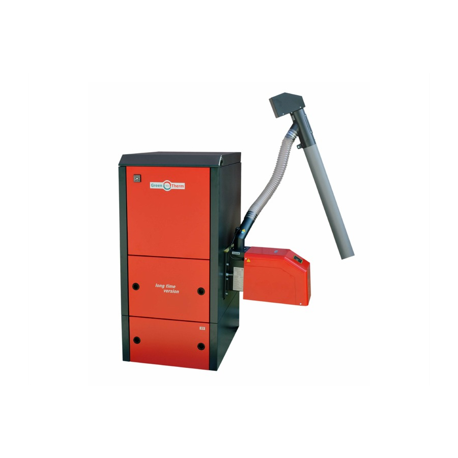
- Page 19 Figure 4.6. View of the system – a hot water pellet boiler from series “Pelletherm V.4 LT” and a pellet burner from series “GP xx sc”. Boiler’s top cover panel Boiler’s convections tract cover Boiler’s combustion chamber cover Pellet burner mounting flange Boiler’s combustion chamber cover panel...
- Page 20 Figure 4.7. Cross section view of a hot water boiler from series “Pelletherm V.4 LT” with presented flue gas direction and its construction main modules. Boiler top cover panel Flue gas outlet to chimney „Third pass” of flue gasses inside the boiler „Second pass”...
-
Page 21: Installation Of The System
INSTALLATION OF THE SYSTEM. 5.1. REQUIREMENTS FOR INSTALLATION OF PELLET BURNER WITH SELF- CLEANNING “GP XX SC” TO A HOT WATER BOILER “PELLETHERM V.4 LT”. The automated pellet burner from series “GP xx sc” is usually mounted on the heat exchanger unit of a hot water boiler from series “Pelletherm V.4 LT”. -
Page 22: Installation Of The System
opens if the operation pressure of the boiler exceeds (0.25 MPa) and is also certified according to PED 97/23; Before initialization of the system to operation must ensure that the heating installation is fully filled with water/circulations liquid and air freed. The system’s normal operation maintenance (switching, refueling, user adjustments, etc.) must be performed only by adult persons, which are well familiar with the appliance user manual. -
Page 23: Connecting To The Chimney
ensure correct and reliable operation of the boiler it is necessary to evenly level it, in order to provide its proper air freeing. 5.4.1. CONNECTING TO THE CHIMNEY. After installation and evening of the boiler it must be connected to a chimney, by ensuring the requirements for efficient and reliable operation of the system. - Page 24 Figure 5.2. View of the connection flange for mounting of the automated pellet burner to the boiler (the presented model is with left mounting of the pellet burner). Side flange for mounting of the pellet burner Threaded studs for mounting of a pellet burner “GP xx sc”...
-
Page 25: Installation Of The Directing Fire-Clay Bricks In The Heat Exchanger Unit's Combustion Chamber
5.4.4. INSTALLATION OF THE DIRECTING FIRE-CLAY BRICKS IN THE HEAT EXCHANGER UNIT’S COMBUSTION CHAMBER. The fire-clay bricks must be positioned in the heat exchanger’s combustion chamber. They are provided together with the boiler’s delivery kit (during transportation of the system the bricks are packed and positioned in the ash tray inside the boiler’s combustion chamber). - Page 26 This cover-flap is used to direct the flue gasses from the second to the third pass of the boiler and also in case of emergency situations (for example if high flue gas pressure inside the boiler occurs) it should be opened, in order to decrease the pressure pulsations.
-
Page 27: Installation Of The Boiler's Horizontal Cover Panels
5.4.7. INSTALLATION OF THE BOILER’S HORIZONTAL COVER PANELS. Figure 5.8. Mounting of cover panels to a hot water boiler from series “Pelletherm V.4 LT”. 5.4.8. INSTALLATION OF THE COVER OVER THE BOILER’S CONVECTION TRACT. This cover is equipped with protection element made of stainless steel. Figure 5.9. -
Page 28: Connecting The Automated Pellet Burner From Series "Gp Xx Sc" To The Boiler
This cover is equipped with isolation panel, designed for operation at high temperatures in the boiler’s combustion chamber. Figure 5.10. Directing cover over the boiler’s combustion chamber. Directive cover above the heat exchanger Figure 5.11. The directing covers of the flue tract of the boiler are correctly positioned. These covers are not the same and their positions must not be changed. -
Page 29: Filling The Transport Auger With Fuel
The tilt angle (between the auger axis and the horizontal plane) influences the auger’s productivity, i.e. the fuel feed rate adjusted for specific operation mode. If the tilt angle has been changed, then the burner adjustments have to be changed also, in order to ensure a specified heating output. 5.4.12. - Page 30 Figure 5.12. Exemplar hydraulic scheme for connecting a hot water pellet boiler from series “Pelletherm V.4 LT” to a heating installation, mixing valve and a heat accumulator tank / buffer. Table 5.1 Description of the components on Figure 5.12. DESCRIPTION DESCRIPTION Ball valve Hot water boiler from series...
-
Page 31: Initiation Of The System To Operation
INITIATION OF THE SYSTEM TO OPERATION. The system, consisting of a hot water pellet boiler from series “Pelletherm V.4 LT” and an automated pellet burner from series “GP xx sc”, must be initiated to operation only by specialized company authorized for such activities. 6.1. - Page 32 Switch “START” – is used to submit “START/STOP” command to the burner’s main module from series “GP xx sc”, which executes the relevant function of the burner’s controller; Connector “Room thermostat” – is used to connect a programmable room thermostat, through which the system operation can be managed.
- Page 33 Figure 6.1. Description of the electrical connectors, installed on the boiler’s interface panel. Switch “START” Room thermostat connector Communication connector Pellet burner connector Emergency thermostat Switch “POWER” Fuse Power supply connector Pelletherm V.4 LT...
-
Page 34: Power Supplying Of A Hot Water Boiler "Pelletherm V.4 Lt
6.2.2. POWER SUPPLYING OF A HOT WATER BOILER “PELLETHERM V.4 LT”. The boiler must be connected to the electrical installation, by observing all technical safety requirements. The boiler delivery kit includes power supply cable with connector. The fuel hopper and the automated pellet burner from series “GP xx sc” must be filled with pellets, in order to be transported by the auger to the burner zone. -
Page 35: Pellet Burner From Series "Gp Xx Sc" Operational Parameters For Adjustment
6.2.5. PELLET BURNER FROM SERIES ”GP XX SC” OPERATIONAL PARAMETERS FOR ADJUSTMENT. The parameters defining the operation mode and the heating output of the system are presented in the installation, operation and maintenance manual of the wood pellet burner from series “GP xx sc”. The function and the adjustment of these parameters must be explained to the end user, in order to provide him/her opportunity for flexible and optimal usage of the appliances. -
Page 36: Adjusting The System's Heating Output
It is not recommended to operate the appliance for longer period of time in heating output lower than its minimum output, as presented in Table 4.1, because such operation modes are ineffective and are not economical; In case continues operation of the system is required and especially of the hot water pellet boiler from series “Pelletherm V.4 LT”, in heating output lower than its nominal output, the manufacture company recommends installation of a heat accumulator tank (buffer), in order to ensure effective, economic and reliable operation of the... -
Page 37: Shutting Down The System
Except the above presented method to stop the system’s operation it can be done by pressing the switch “START”, positioned on the interface panel of the hot water boiler from series “Pelletherm V.4 LT”. To restore the system’s operation press this switch again. It is forbidden to stop the appliance during operation through the main switch “POWER”! The recommended stopping, through the switch “START”... -
Page 38: Emergency Stopping Of The System
6.7. EMERGENCY STOPPING OF THE SYSTEM. During operation of the system some of its modules (hot water pellet boiler or pellet burner) might transit to emergency mode situations. Some of these situations would be detected by the relevant module sensors of the system, as emergency prevention procedures will be automatically executed. - Page 39 Figure 6.2. Cleaning of the ash from the boiler’s walls. Figure 6.3. Container for ash. Open the combustion chamber door and take out the ash container, positioned at the boiler’s bottom, gather the ash residues in fire-proof (or another proper) container, after that in reverse order mount the ash container back and close the door, mount the other cover panels of the boiler.
-
Page 40: Safety And Unpredicted Risks
6.9. SAFETY AND UNPREDICTED RISKS. RISKS FROM USAGE OF THE SYSTEM. The modules of the system – a hot water pellet boiler from series “Pelletherm V.4 LT” and an automated pellet burner from series “GP xx sc” are designed and manufactured in compliance with the main safety requirements of the acting European standards and provisions. -
Page 41: Failures And Troubleshooting
7. FAILURES AND TROUBLESHOOTING. In cases of system operation failures its problems and the relevant troubleshooting have to be well known. In the automated pellet burner from series “GP xx sc” manual are presented several tables that include information about possible failures and the methods for removing them. - Page 42 performed by a servicing specialist. Presence of non-ignited If the heating element of the burner, which or burned pellets in the ignites the fuel, is damaged then it must be burner zone, but there is replaced. heating element no burning process operating normally then...
-
Page 43: Wiring Diagram Of A Boiler From Series "Pelletherm V.4 Lt" In Combination With A Pellet Burner From Series "Gp Xx Sc
8. WIRING DIAGRAM OF A BOILER FROM SERIES “PELLETHERM V.4 LT” IN COMBINATION WITH A PELLET BURNER FROM SERIES “GP XX SC”. The control panel wiring diagram of a hot water boiler from series “Pelletherm V.4 LT”, operating in combination with pellet burner from series “GP x sc”, is presented on Figure 8.1. The connectors CONN1 –... - Page 44 Figure 8.1. Control panel wiring diagram of a hot water pellet boiler from series “Pelletherm V.4 LT”, co-operating as a system together with a pellet burner from series “GP xx sc”. Pelletherm V.4 LT...
- Page 45 Figure 8.2. Wiring diagram of the boiler’s connector panel used to connect the pellet burner. Pelletherm V.4 LT...
- Page 46 Pelletherm V.4 LT...
-
Page 47: Warranty Conditions
WARRANTY CONDITIONS The manufacture company guarantees correct and failsafe operation of the system appliances only when the requirements for installation and operation are observed during initialization and maintenance. The warranty start date of the system’s modules (a hot water pellet boiler from series “Pelletherm V.4 LT”... - Page 48 Pelletherm V.4 LT...