Table of Contents
Advertisement
Advertisement
Table of Contents

Related Manuals for ELIKA 460

Summary of Contents for ELIKA 460
- Page 1 ELIKA Access Cont r ol S yst em I N S TA L L AT I O N M A N U A L...
- Page 2 While being one of the most advanced entry systems in the world, our greatest accomplishment is delivering simple systems to install, program, and operate. The Elika 460 incorporates the latest technologies to provide security, convenience and functionality. Rethink, your access control with Elika.
-
Page 3: What Is Included
WHAT IS INCLUDED: INSTALLATION INSTRUCTION MANUAL BLUETOOTH BOARD (OPTIONAL) SOFTWARE SETUP MANUAL CHARGER BOARD (OPTIONAL) WEB APPLICATION MANUAL REGISTRATION CARD LABELS 2 SECURITY SCREW DRIVERS ENTER CELL BOARD (OPTIONAL) CALL VoIP BOARD (OPTIONAL) HELP ELIKA TECHNICAL SUPPORT 1.949.208.3600... -
Page 4: Parts Diagram
Battery Pack EL460A-1240 Battery Backup Kit Charger Board EL460A-1250 Door Strap EL460A-1260 Battery Holder EL460A-1270 Courtesy Light Board EL460A-1280 Main Housing EL460A-1290 Antenna Cap EL460A-1300 Hardware Kit EL460A-1310 Fuse Kit EL460A-1320 Weldable Steel Mounting Plate EL460A-PLT ELIKA TECHNICAL SUPPORT 1.949.208.3600... -
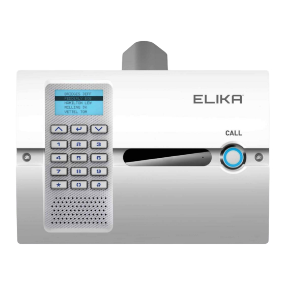
Page 5: Elika 460 References
ELIKA 460 REFERENCES: SPEAKER CALL BUTTON KEYPAD DAYLIGHT SENSOR SECURITY SCREWS CAMERA LIGHT SENSOR LCD SCREEN CAMERA ANTENNA CAP FRONT LENS HOUSING MICROPHONE ELIKA TECHNICAL SUPPORT 1.949.208.3600... -
Page 6: Main Board References
EXPANSION PORT 3 RELAY 1 CONNECTOR EXTERNAL ALARM CONNECTOR MAIN POWER CONNECTOR POWER CONNECTOR TO FRONT BOARD 2A FUSE RELAY 1 LED VoIP & CELL BOARDS INTERFACE POWER LED EXPANSION PORT 1 RELAY 2 LED WIEGAND PORT ELIKA TECHNICAL SUPPORT 1.949.208.3600... -
Page 7: Front Board References
SPEAKER CONNECTOR VOIP BOARD AUDIO CONNECTOR BLUETOOTH BOARD INTERFACE CELL BOARD AUDIO CONNECTOR POWER CONNECTOR FROM MAIN BOARD EXPANSION PORT CAMERA CONNECTOR LCD RIBBON CONNECTOR COURTESY LIGHT CONNECTOR LCD BACKLIGHT CONNECTOR CALL BUTTON CONNECTOR POWER LED ELIKA TECHNICAL SUPPORT 1.949.208.3600... -
Page 8: Expansion Board References
DATA LED WI-FI ANTENNA CONNECTOR SIM CARD LED BLUETOOTH ANTENNA CONNECTOR POWER LED COURTESY LIGHT CABLE ETHERNET PORT DC POWER SUPPLY INPUT INTERFACE CONNECTOR DC POWER OUTPUT TO MAIN BOARD VoIP HARNESS CONNECTOR CHARGER LED BATTERY CONNECTOR ELIKA TECHNICAL SUPPORT 1.949.208.3600... -
Page 9: Table Of Contents
TABLE OF CONTENTS: WHAT IS INCLUDED PARTS DIAGRAM ELIKA 460 REFERENCES MAIN BOARD REFERENCES FRONT BOARD REFERENCES EXPANSION BOARD REFERENCES IMPORTANT SAFETY INFORMATION General Safety Precautions..................... 9 IMPORTANT INSTALLATION INFORMATION 10-12 Important Information For Pedestrian Door Access Control......10-11 Important Information For Vehicular Gate Access Control........ 12 GENERAL SPECIFICATIONS Specifications........................ -
Page 10: Important Safety Information
See VoIP Over Ethernet Setup on Page 22 Wi-Fi Installation Verify a strong signal strength at the installation location See VoIP Over Wi-Fi Connectivity Setup Using Android on Page 21 See VoIP Over Wi-Fi Connectivity Setup Using Apple on Page 22 ELIKA TECHNICAL SUPPORT 1.949.208.3600... -
Page 11: Important Information For Pedestrian Door Access Control
12" Optional post and base 48" MIN Elevation Plan a) Side Reach Dimensions 12" Optional post and base 30" MIN Elevation Plan b) Forward Reach Dimensions ELIKA TECHNICAL SUPPORT 1.949.208.3600... - Page 12 Where the reach depth exceeds 10 inches (255 mm), the high side reach shall be 46 inches (1170 mm) maximum for a reach depth of 24 inches (610 mm) maximum. Figure 308.2.1 Unobstructed Forward Reach Figure 308.2.2 Obstructed High Forward Figure 308.3.1 Unobstructed Side Reach Figure 308.3.2 Obstructed High Side Reach ELIKA TECHNICAL SUPPORT 1.949.208.3600...
-
Page 13: Important Information For Vehicular Gate Access Control
IMPORTANT INFORMATION FOR VEHICULAR GATE ACCESS CONTROL DONT’S Don’t install the Elika access system so that user vehicles are in the path of the moving gate. Don’t install the Elika access system in such a way that the controls are blocking the vehicular pathways or force pedestrian traffic into vehicular pathways. -
Page 14: General Specifications
1A plug in transformer 12V Solar Panel 7.4V 4AHr Battery Pack (optional charger required) OPERATING CURRENT: Cell Module Option - 300mA during operation VoIP Module Option - 300mA during operation Camera Option - 200mA during operation ELIKA TECHNICAL SUPPORT 1.949.208.3600... -
Page 15: Physical Dimensions
PHYSICAL DIMENSIONS: 12” 8-1/4” Front face dimensions 4-1/4” Top housing dimensions 2-1/2” Hole mounting dimensions ELIKA TECHNICAL SUPPORT 1.949.208.3600... -
Page 16: Housing Installation
Loosen the screws mounting the Main Board See Figure 15.1 ANTENNA INSTALLATION If you need to install antennas to the Elika access system Remove the antenna cap Install the coaxial cables provided for the antennas. Keep in mind that the Cellular antenna must be at the front (this... - Page 17 See Figure 16.1 REINSTALL Reinstall the Main Board See Figure 16.2 COAXIAL CONNECTION Connect your coaxial cable (from the antenna) to your respective wireless module Figure 16.1 - Housing Mounting Figure 16.2 - Main Board Installation ELIKA TECHNICAL SUPPORT 1.949.208.3600...
-
Page 18: Wall Mount Installation
INTENTIONALLY BLANK ELIKA TECHNICAL SUPPORT 1.949.208.3600... -
Page 19: Electrical Installation
To minimize the effects caused by lightning, follow these guidelines. Use a ground rod to provide a ground reference. Consult your city code and be aware of under-ground services in the site of the Elika access system to prevent inconveniences. - Page 20 NOTE: That the external device will need to be a 12V external device EXPANSION BUS CONNECTIONS Connect the Expansion Bus wires to D+ and D- for additional Elika devices control WIEGAND DEVICES CONNECTIONS Connect the Wiegand devices to the Wiegand Connector...
- Page 21 Connect the solar panel to the Input, be careful about polarity of the wires Connect the “Load” wires from the Charger board to the “Power” connector on the Main Board. CAUTION: These connections are polarity sensitive. ELIKA TECHNICAL SUPPORT 1.949.208.3600...
-
Page 22: Wifi Connectivity Setup
Select the Serial Number of the unit you are setting up (the serial number is locate in registration card) Enter the password for the Elika unit: A unique password is provided with your VoIP Module Wait for connection The app will connect to the unit Select "Next Step"... -
Page 23: Voip Over Wi-Fi Connectivity Setup Using Apple Devices
Step 1 Leave the App and go to “settings” on your phone Step 2 Select the Elika Wi-Fi from the Wi-Fi Setting Elika-460-xxxx (serial Number of the device you are setting up, the serial number is locate in registration card) Enter the password to join this network, •... -
Page 24: Troubleshooting
LED REFERENCES The following table describes the meaning of the various LEDs on the Elika 460 unit. In the event you do not have the LEDS at the normal condition after power up and few minutes of initialization, then make sure all the wire harnesses are properly connected, make sure the antennas are properly connected and recycle the power of the unit. - Page 25 Gate or Door hold Programming Check your Web App and open verify your programming settings 7-Day timer Clear or update your 7-day timer settings Latch Code Enter the proper latch code to ELIKA TECHNICAL SUPPORT 1.949.208.3600 close again...
- Page 26 Wiegand device with 3 digit for facility code and 5 digits for ID Data 0 and/or Data 1 not Verify your connections from properly connected your Wiegand device. Front view from top to bottom: Data 0 ELIKA TECHNICAL SUPPORT 1.949.208.3600...
- Page 27 Use the History to check the code received by the unit for verification purposes LCD Screen always Elika unit failing to connect Verify Elika unit and Elika Web displays to Elika DNS app are pointing to the same “Connecting...” DNS.
-
Page 28: Apendix A
FULL WIRING DIAGRAM: REQUIRED FOR BATTERY BACKUP 12-16 12V SOLAR 12-16 INPUT CHARGER BOARD BATTERY PACK MAIN BOARD CAMERA COURTESY KEYBOARD LIGHT BOARD VoIP BOARD SPEAKER CALL 5-WIRE BUTTON BLE BOARD MAIN BOARD 5-WIRE CELL BOARD FRONT BOARD ELIKA TECHNICAL SUPPORT 1.949.208.3600... -
Page 29: Apendix B
fire or explosion from vented gases. Observe proper precautions. Observe proper polarity orientation between the battery and charging circuit. SOLAR PANEL SELECTION Solar panel(s) are sold separately. Use only UL Listed 12V solar panel(s), such as Elika part #s: OPEN-CIRCUIT SHORT-CIRCUIT WATTAGE... - Page 30 If more specific Information is needed please consult with Elika Access Systems. For more infor- mation regarding solar energy refer to: http://rredc.nrel.gov/solar/pubs/redbook/...
-
Page 31: Battery Backup Installation
Reinstall the Main Board Figure B.1 - Main Board See Figure B.1 Connect the “LOAD” wires from the Charger Board to the “POWER” Connector on the Main Board. See Figure B.1 Figure B.2 - Installing the Charger Board ELIKA TECHNICAL SUPPORT 1.949.208.3600... - Page 32 LED will be off. Figure B.4 - Connect the See Figure B.5 Battery Pack 12-16 SOLAR 12-16 INPUT CHARGER BOARD BATTERY PACK MAIN BOARD Figure B.5 - Power Supply to Main Board ELIKA TECHNICAL SUPPORT 1.949.208.3600...
-
Page 33: Apendix C
Board (Use the front most location for the cell antenna) Secure the antenna Reinstall the antenna cap See Figure C.2 Figure C.1 - Main Board Removal Reinstall the Main Board See Figure C.1 Figure C.2 - Cell Antenna Installation ELIKA TECHNICAL SUPPORT 1.949.208.3600... - Page 34 LEDs are illuminated on the Cell Board after the power up initialization time See Figure C.6 Figure C.4 - Installing the Cell Board Figure C.5 - Connecting the Cell Harness Figure C.6 - Main Board Reconnection ELIKA TECHNICAL SUPPORT 1.949.208.3600...
-
Page 35: Apendix D
Install the Coaxial cable for the Wi-Fi connectivity Secure the antenna Reinstall the antenna cap See Figure D.2 Reinstall the Main Board Figure D.1 - Main Board Removal See Figure D.1 Figure D.2 - VoIP Antenna Installation ELIKA TECHNICAL SUPPORT 1.949.208.3600... - Page 36 Data LEDs are illuminated on the VoIP Board after the power up initialization time See Figure D.6 Figure D.4 - Installing the VoIP Board Figure D.5 - Connecting the VoIP Harness Figure D.6 - Main Board Reconnection ELIKA TECHNICAL SUPPORT 1.949.208.3600...
-
Page 37: Apendix E
Install the Coaxial cable for the Bluetooth connectivity Secure the antenna Reinstall the antenna cap See Figure E.2 Reinstall the Main Board Figure E.1 - Main Board Removal See Figure E.1 Figure E.2 - BLE Antenna Installation ELIKA TECHNICAL SUPPORT 1.949.208.3600... - Page 38 INSTALLING THE BLE BOARD Install the Bluetooth Board into the Front Board See Figure E.3 RECONNECTION Reconnect the power connector in the Main Board See Figure E.4 Figure E.3 - Installing BLE Board Figure E.4 - Main Board Reconnection ELIKA TECHNICAL SUPPORT 1.949.208.3600...
-
Page 39: Apendix F
See Figure F.1 Remove the keypad cable REMOVE THE FRONT BOARD Be careful with the exiting connections and wire harnesses already in place Figure F.1 - Front Board Power See Figure F.2 Figure F.2 - Remove front board ELIKA TECHNICAL SUPPORT 1.949.208.3600... - Page 40 Connect the Camera Harness and any other harness back onto the Front Board See Figure F.4 Connect the Power Connector from Figure F.3 - Place the camera the Front Board. Figure F.4 - Front Board Reconnection ELIKA TECHNICAL SUPPORT 1.949.208.3600...
- Page 41 ELIKA TECHNICAL SUPPORT 1.949.208.3600...
- Page 42 ELIKA TECHNICAL SUPPORT 1.949.208.3600...
- Page 43 OUR CONTINUOUS COMMITMENT TO EXCELLENCE Elika Access Systems is committed to advancing the industry through the highest quality standards, state of the art technology and the simplest user interfaces available. We stand behind all of our products and offer full support whether you are a distributor, installer or end user.
- Page 44 • elika@elikaaccess. com • 949-208-3600...
Need help?
Do you have a question about the 460 and is the answer not in the manual?
Questions and answers