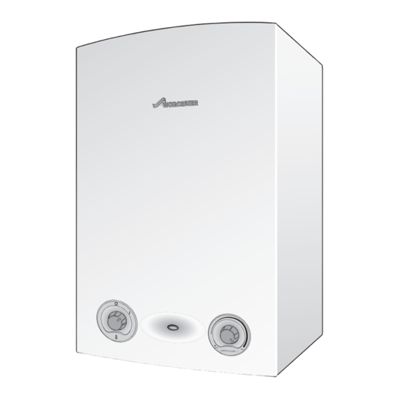
GREENSTAR 12Ri ErP Installation, Commissioning And Servicing Instructions

GREENSTAR 12Ri ErP Installation, Commissioning And Servicing Instructions

Wall hung rsf gas fired condensing boiler
Table of Contents

Advertisement

Quick Links

INSTALLATION, COMMISSIONING AND SERVICING INSTRUCTIONS
WALL HUNG RSF GAS FIRED CONDENSING BOILER
Greenstar Ri
FOR OPEN VENTED & SEALED CENTRAL HEATING SYSTEMS & INDIRECT MAINS FED DOMESTIC HOT WATER
ErP
These appliances are for use with:
Natural Gas or L.P.G.
(Cat. II 2H 3P type C13, C33 & C53)
Model
Natural Gas
12Ri
ErP
15Ri
ErP
18Ri
ErP
24Ri
ErP
LPG
12Ri
ErP
15Ri
ErP
18Ri
ErP
24Ri
ErP
If you smell gas:
▶ Well away from the building: call the National Gas Emergency
Service on 0800 111 999.
▶ L.P.G. boilers: Call the supplier's number on the side of the gas tank.
GC Number
41-406-41
41-406-43
41-406-45
41-406-47
41-406-42
41-406-44
41-406-46
41-406-48

Advertisement

Table of Contents
loading

Summary of Contents for GREENSTAR 12Ri ErP

  • Page 1 INSTALLATION, COMMISSIONING AND SERVICING INSTRUCTIONS WALL HUNG RSF GAS FIRED CONDENSING BOILER Greenstar Ri FOR OPEN VENTED & SEALED CENTRAL HEATING SYSTEMS & INDIRECT MAINS FED DOMESTIC HOT WATER These appliances are for use with: Natural Gas or L.P.G. (Cat. II 2H 3P type C13, C33 & C53)
  • Page 2: Table Of Contents

    Protection function ......51 Greenstar Ri - 6 720 813 283 (2015/07)
  • Page 3: Key To Symbols And Safety Precautions

    To refer the reader to a specific figure/table/section within the manual.  e.g. figure 1. A reference number to identify or refer to a part or item. In a related figure, items or parts identified by a sequential number. Greenstar Ri - 6 720 813 283 (2015/07)
  • Page 4: Safety Precautions

    Installers are required to carry out installation, commissioning and servicing work in accordance with the Benchmark Code of Practice which is available from the Heating and Hotwater Industry Council who manage and promote the scheme. Visit centralheating.co.uk for more information. Greenstar Ri - 6 720 813 283 (2015/07)
  • Page 5: Regulations

    All seals, joints and compounds (including flux and solder) and components used as part of the secondary domestic water system must be approved by WRAS. CH Water Artificially softened water must not be used to fill the central heating system. Greenstar Ri - 6 720 813 283 (2015/07)
  • Page 6: Appliance Information

    Do not use the pre-formed copper pipes supplied with the boiler for the gas supply. - HARDWARE LITERATURE PACK: Qty. These copper pipes are for water only. Greenstar Ri Installation, Commissioning and Servicing Instructions Users Instructions STANDARD PACKAGE: Consumer Guarantee Card...
  • Page 7: Technical Data

    27.4 27.4 27.4 27.4 27.4 Lift weight 22.6 22.6 22.6 22.6 22.6 22.6 22.6 22.6 SEDBUK band SEDBUK 2005 90.1 90.1 90.1 90.2 91.4 91.4 91.4 92.0 Table 5 Technical data Ri Greenstar Ri - 6 720 813 283 (2015/07)
  • Page 8: Energy Efficiency

    The following product data satisfy the requirements of the EU Regulations No. 811/2013 and No. 812/2013 supplementing Directive 2010/30/EU. Product data Symbol Unit 7733600074 7733600072 7733600070 7733600068 Product type – – 12Ri ErP NG 15Ri ErP NG 18Ri ErP NG 24Ri ErP NG Condensing boiler – –...
  • Page 9 1) High-temperature regime means 60 °C return temperature at heater inlet and 80 °C feed temperature at heater outlet. 2) Low temperature means for condensing boilers 30 °C, for low-temperature boilers 37 °C and for other heaters 50 °C return temperature (at heater inlet). Greenstar Ri - 6 720 813 283 (2015/07)
  • Page 10: Boiler Main Components

    Flue air pressure switch connection Access panel - Heat Exchanger/Sump cleaning Return connector with drain point Manual vent point Flow connector Fan pressure test point Boiler Temperature control and Reset knob Air pressure switch Greenstar Ri - 6 720 813 283 (2015/07)
  • Page 11: Pre-Installation

    Worcester, Bosch Group supports the use of Fernox F4 leak sealer. WATER TREATMENT PRODUCTS Suitable water treatment products can be obtain from the following manufacturers: FERNOX 0870 601 5000 or www.fernox.com SENTINEL 0800 389 4670 or www.sentinel-solutions.net Greenstar Ri - 6 720 813 283 (2015/07)
  • Page 12 3 bar pressure relief valve Stop cock Table 8 Key to figures 3, 4 & 5 NOTICE: A drain cock should be fitted at the lowest point of the heating circuit and beneath the appliance. Greenstar Ri - 6 720 813 283 (2015/07)
  • Page 13: Condensate Pipe Work

    Minimum 450mm and up to three storeys Visible air break at plug hole Sink or basin with integrated overflow 75mm sink waste trap Condensate pump Condensate trap of 75mm already incorporated into the boiler Greenstar Ri - 6 720 813 283 (2015/07)
  • Page 14: External Connections

    ▶ The external pipe should take the shortest and least exposed route to chippings to a depth of 400mm. the discharge point, and should "fall" as steeply as possible away from the boiler, with no horizontal runs in which condensate might stand. Greenstar Ri - 6 720 813 283 (2015/07)
  • Page 15: Pressure Relief Pipe Work

    • The pressure relief drain pipe (1) from the boiler should be at least 15mm diameter copper pipe and run downwards, away from any electrical equipment or other hazard, preferably to an external drain or soak away. Greenstar Ri - 6 720 813 283 (2015/07)
  • Page 16: Compartments

    Unventilated Compartment Installation Clearances (millimetres) Suggested total unventilated compartment minimum clearances are: Side Above Below Front (to removable door) 400mm 170mm approx. 200mm 100mm (30mm above elbow) Table 12 Minimum unventilated compartment clearances Greenstar Ri - 6 720 813 283 (2015/07)
  • Page 17: Plumbing Manifold

    Further guidance on pipe routing can be found printed on the boiler template (supplied with the boiler). Return Flow reset Fig. 19 Pipe work dimensions Pipes in alternative position Fig. 18 Plumbing manifold Greenstar Ri - 6 720 813 283 (2015/07)
  • Page 18: Flue Options

    4.8.1 Flue lengths The flue systems have different maximum flue lengths The Greenstar series has the option of two horizontal 60/100 RSF (telescopic and longer telescopic) and one horizontal 80/125 RSF Maximum flue length (telescopic) flue system and two vertical RSF (60/100 or 80/125) flue...
  • Page 19 Maximum flue length 60/100 80/125 (mm) High level horizontal flue with 3 x 90° bends N/A 9,000 60/100 80/125 Vertical balanced flue with 2 x 45° bends 4,400 13,000 Table 24 Table 27 Greenstar Ri - 6 720 813 283 (2015/07)
  • Page 20: Flue Terminal Positions

    14. 500mm clearance to any vertical structure on a roof, 600mm to room sealed flue or 1,500 to an open flue. 15. 200mm below eaves and 75mm below gutters, pipe and drains. Greenstar Ri - 6 720 813 283 (2015/07)
  • Page 21: Plume Management Terminal Positions

    10° fall back, (stop tabs in the elbow prevent less manufacturer. than 10°) to the appliance for proper disposal of condensate. Any further horizontal runs can be 3°. Greenstar Ri - 6 720 813 283 (2015/07)
  • Page 22: Determine The Plume Management System Length

    ▶ The Plume management extension kit contains the components required for such a configuration. Maximum plume management length The Greenstar Ri range appliances can use up to 4,500mm of plume management regardless of flue length. Fig. 25 Unpacking 2 Greenstar Ri...
  • Page 23: Wall Mounting Template & Flue Opening

    ▶ If extensions are to be added then the complete flue must rise at an angle of 3°. ▶ The 125mm diameter flue system will require the flue to rise at an angle of 3°. ▶ Drill hole using a core drill or similar. SIDE OUTLET: Greenstar Ri - 6 720 813 283 (2015/07)
  • Page 24: Outer Case Removal

    System pipes may be run vertically up behind the boiler or below it. NOTICE: ▶ If pipes require reducing in length this is best done before they are fitted to the boiler. 6720804514-02.1Wo Fig. 27 Case removal Greenstar Ri - 6 720 813 283 (2015/07)
  • Page 25: Condensate Connection

    ▶ Fit retaining screws through the holes (2) in the boiler frame to secure the boiler. ▶ Make connections to the heating system pipes. 6720644744-56.1Wo Fig. 29 Levelling and securing detail Greenstar Ri - 6 720 813 283 (2015/07)
  • Page 26: Flue Turret/Adaptor Installation

    (flue bracket 100mm part number: 7 716 191 177, flue brackets 100mm x 6 part number: 7 716 191 178, flue bracket 125mm part number: 7 716 191 179) Greenstar Ri - 6 720 813 283 (2015/07)
  • Page 27: Electrical Connections

    5. Boiler Demand (from external wiring centre) (ST2): – Connect SWITCHED LIVE wire to terminal (LR). NOTICE: SYSTEM PUMP ▶ THE SYSTEM PUMP MUST BE CONNECTED TO THE APPLIANCE FOR THE PUMP OVER-RUN FUNCTION. Greenstar Ri - 6 720 813 283 (2015/07)
  • Page 28: Commissioning

    Fig. 37 rectification work, shut off the gas and water supply and ▶ Check the gas type specified on the identification plate (1) matches electrically isolate the boiler. that of the gas supply. Greenstar Ri - 6 720 813 283 (2015/07)
  • Page 29: Filling The System

    ▶ Run the boiler/system at normal operating temperature for the time stated by the manufacturer of the flushing agent. RESET RESET ▶ Drain and thoroughly flush the system to remove the flushing agent reset and debris. Fig. 41 Boiler controls Greenstar Ri - 6 720 813 283 (2015/07)
  • Page 30: Commissioning

    – The boiler will stay at maximum for 15 minutes. – Return the boiler to normal after the checks. ▶ Check the gas supply working pressure at the gas valve conforms to values shown in Fig. 43 or Fig. 44 . Greenstar Ri - 6 720 813 283 (2015/07)
  • Page 31: Checking The Gas Rate

    Boiler is operating call Worcester, Bosch CO < 350ppm satisfactorily. Group help line. CO/CO ratio No further action 0330 123 3366 < 0.004 is required. 6720809056-01.2Wo Fig. 45 Combustion check flow chart Greenstar Ri - 6 720 813 283 (2015/07)
  • Page 32: Finishing Commissioning

    Guarantee registration 2. Push up into position. Your Greenstar appliance carries a guarantee against faulty material or 3. Secure in position the screw provided. manufacture subject to Terms and Conditions. Guarantee Registration can be completed: •...
  • Page 33: Service And Spares

    2. Undo but do not remove the two screws securing boiler casing at the bottom of the appliance. ▶ Pull case forward and remove. 6720644744-36.1Wo Fig. 49 Control panel into service position Greenstar Ri - 6 720 813 283 (2015/07)
  • Page 34: Checking Gas Inlet Pressure

    ▶ If the readings are outside these limits then this indicates that there is a problem with the flue system or combustion circuit, e.g. missing or dislodged seals. NORM 6720644744-31.1Wo Fig. 52 Setting the boiler to maximum Fig. 51 Flue integrity test Greenstar Ri - 6 720 813 283 (2015/07)
  • Page 35: Flue Gas Analysis

    3. Cleanliness of the heat cell, plus blockages in the condensate 2. Remove the sump cover. disposal. 3. Clean the sump with a suitable brush. ▶ Check the exhaust path and flue for restriction. ▶ Re-check the Fan Pressure readings Greenstar Ri - 6 720 813 283 (2015/07)
  • Page 36: Setting The Air/Gas Ratio

    1. Refer to figure 59 and undo the securing nut on the top of the heat exchanger and remove the retaining plate assembly. 6720643895-66.1Wo Fig. 57 Gas valve adjustment CO/CO settings for Greenstar Ri CO/CO should be measured after 10 minutes. Gas type max.
  • Page 37 ▶ Do not use wire wool to clean the electrodes ▶ Inspect the condition of the electrodes and ceramics, replace if necessary. ▶ Use a plastic scouring pad to clean the electrodes. 6720644744-40.1Wo Fig. 63 Access cover removal BAFFLE REMOVAL Greenstar Ri - 6 720 813 283 (2015/07)
  • Page 38: Syphon Removal And Cleaning

    “Setting the air/gas ratio” on page 36. ▶ When replacing the burner gasket ensure that the clamping plate is fully tightened down to the heat exchanger. Greenstar Ri - 6 720 813 283 (2015/07)
  • Page 39: Replacement Of Parts

    1. Undo the two screws securing the top of the boiler casing. 2. Undo the two screws securing the bottom of the boiler casing. ▶ Pull case forward and remove. Fig. 68 Primary sensor and overheat thermostat Fig. 67 Remove outer case Greenstar Ri - 6 720 813 283 (2015/07)
  • Page 40: Flue Overheat Thermostat (With Grommet)

    Fig. 71 Control panel into service position Fig. 70 Remove thermostat To replace, push the thermostat and new grommet gently back into the opening until contact with the locating ridge is felt. Greenstar Ri - 6 720 813 283 (2015/07)
  • Page 41: Gas Valve

    Gas ratio”. Measurement and setting (if necessary) of the gas ratio must not be attempted unless the person is equipped with a combustion analyser conforming to BS 7927 and is competent in its use. Greenstar Ri - 6 720 813 283 (2015/07)
  • Page 42: Air Pressure Switch

    – Press the two lugs on the back of the flap into the two slots in the flap valve assembly. Fig. 77 Air pressure switch bracket NOTICE: After re-assembly, check the CO/CO levels as described in section 7.6 Setting the air/gas ratio. 6720643895-117.1Wo Fig. 79 Flap valve assembly Greenstar Ri - 6 720 813 283 (2015/07)
  • Page 43: Electrode Assembly And Burner

    ▶ Ensure that the new gasket is fitted, with the electrode assembly and gasket heat shield CAUTION: Clamping plate ▶ Ensure that the clamping plate is firmly tightened down on top of the heat exchanger. Greenstar Ri - 6 720 813 283 (2015/07)
  • Page 44: Heat Exchanger

    Fig. 87 Sump connections hook. 1. Refer to figure 88 and lift the heat exchanger up to clear. 3. Pull the upper exhaust connector down. 2. Pull the heat exchanger forward from the case. Greenstar Ri - 6 720 813 283 (2015/07)
  • Page 45: Syphon Removal

    5. Remove the rear panel. 6. Remove the transformer cover. 7. Remove the printed circuit board. 6720644744-42.1Wo Fig. 89 Syphon removal 7.8.14 ACCESS TO BOILER CONTROL COMPONENTS 1. Remove three screws. 2. Remove cover from control. Greenstar Ri - 6 720 813 283 (2015/07)
  • Page 46 ▶ The appliance will indicate an error and will not function correctly. NOTICE: CO/CO ▶ After completing the service of the control, the CO/ must be checked and set to the limits shown in “Setting the air/gas ratio” in section 7.6. Greenstar Ri - 6 720 813 283 (2015/07)
  • Page 47: Short Parts List

    8 716 113 851 0 8 716 111 209 0 Fuse F1 Fuse F2 Wall mounting template:- 8 718 689 070 0 8 716 156 000 0 8 716 156 001 0 GC No. E27-716 Greenstar Ri - 6 720 813 283 (2015/07)
  • Page 48: Fault Finding And Diagnosis

    ▶ Code plug – Is code plug missing or not inserted properly. 2 pulses Service mode switch in min. position 5 pulses Service mode switch in max. position Table 31 Fault finding Greenstar Ri - 6 720 813 283 (2015/07)
  • Page 49: Internal Wiring Diagram

    AC 230 V DIAGNOSTIC CODE INTERFACE PLUG Norm MODE SWITCH LP NP LR LP NP LR Green Earth Colour sequence † Blue Violet Orange MAINS SUPPLY EXTERNAL PUMP 230V WIRING CENTER/ JUNCTION BOX 6720644744-27.2Wo Greenstar Ri - 6 720 813 283 (2015/07)
  • Page 50: Boiler Function

    FAULT FINDING AND DIAGNOSIS BOILER FUNCTION Fig. 92 Boiler function Greenstar Ri - 6 720 813 283 (2015/07)
  • Page 51: Protection Function

    No central heating Pump runs 5 seconds A central heating demand every 24hrs from demand after activated, pump runs last time pump ran a 24hr period normally 6720643895-111.1Wo Fig. 93 Protection function Greenstar Ri - 6 720 813 283 (2015/07)
  • Page 52 NOTES Greenstar Ri - 6 720 813 283 (2015/07)
  • Page 53 NOTES Greenstar Ri - 6 720 813 283 (2015/07)
  • Page 56 WORCESTER, BOSCH GROUP: TECHNICAL SUPPORT: 0330 123 3366 APPOINTMENTS: 0330 123 9339 SPARES: 0330 123 9779 LITERATURE: 0330 123 9119 TRAINING: 0330 123 0166 SALES: 0330 123 9669 Worcester, Bosch Group Cotswold Way, Warndon, Worcester WR4 9SW. Tel. 0330 123 9559 Worcester, Bosch Group is a brand name of Bosch Thermotechnology Ltd.

This manual is also suitable for:

15ri erp18ri erp24ri erp

Table of Contents