Table of Contents
Advertisement
Quick Links
LCR METER
Model : LCR-9073A
OPERATION MANUAL
Your purchase of this LCR
METER
marks
forward for you into the
f i e l d
o f
measurement.
this
LCR
METER
complex
and
instrument,
structure will allow many
years of use if proper
operating techniques are
developed.
Please
the following instructions
carefully and always keep
this manual within easy
reach.
a
step
p r e c i s i o n
Although
is
a
delicate
its
durable
read
Advertisement
Table of Contents

Related Manuals for SUNWE LCR-9073A


Summary of Contents for SUNWE LCR-9073A
- Page 1 LCR METER Model : LCR-9073A Your purchase of this LCR METER marks step forward for you into the f i e l d p r e c i s i o n measurement. Although this METER complex delicate instrument, durable...
-
Page 2: Table Of Contents
TABLE OF CONTENTS 1. FEATURES..............1 2. SPECIFICATIONS............1 2-1 General Specifications..........1 2-2 Electrical specifications.........3 3. FRONT PANEL DESCRIPTION........6 3-1 Display .............. 6 3-2 LCD backlight ON/OFF button.......6 3-3 LC/R select switch ..........6 3-4 Function rotary switch/Power switch..... 6 3-5 L/C Measuring terminal 1........ -
Page 3: Features
1. FEATURES * Professional LCR meter, used the LSI-circuit and exclusive microprocessor circuit, high reliability and High measuring accuracy. * Wide ranger measurement for Inductance, Capacitance and Resistance measurement. * Test frequency : 100 Hz, 1 KHz. * Input overload protection * Rotary switch function selector. - Page 4 Data Output RS 232/USB PC computer interface. * Connect the optional RS232 cable UPCB-02 will get the RS232 plug. * Connect the optional USB cable USB-01 will get the USB plug. Over Input Show " 1 " indicator. Indication Operating to 50 ( 32 to 122...
-
Page 5: Electrical Specifications
2-2 Electrical specifications ( 23 ± 5 ℃ L ( Inductance ) Range Resolution Test Accuracy Frequency 2 mH 1 uH 1 kHz ± ( 2 %+2d ) 20 mH 10 uH 1 kHz ± ( 2 %+2d ) 200 mH 100 uH 1 kHz ±... - Page 6 C ( Capacitance ) Range Resolution Test Accuracy Frequency 2 nF 1 pF 1 kHz ± ( 2 %+2d ) 20 nF 10 pF 1 kHz ± ( 2 %+2d ) 200 nF 100 pF 1 kHz ± ( 2 %+2d ) 2 uF 0.001 uF 1 kHz...
-
Page 7: Diode Test
R ( Resistance ) Range Resolution Accuracy 200 Ω 0.1Ω ± ( 1 % + 2d ) 2 kΩ 1 Ω ± ( 1 % + 2d ) 20 kΩ 10 Ω ± ( 1 % + 2d ) 200 kΩ 100 Ω... -
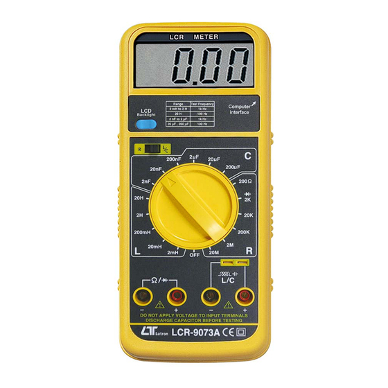
Page 8: Front Panel Description
3. FRONT PANEL DESCRIPTION Fig. 1 3-1 Display 3-2 LCD backlight ON/OFF button 3-3 LC/R select switch 3-4 Function rotary switch/Power switch 3-5 L/C Measuring terminal 1 3-6 L/C Measuring terminal 2 3-7 Resistance/Diode Measuring terminal 3-8 RS-232 Output Terminal 3-9 Stand 3-10 Battery cover Screw 3-11 Battery Compartment/Cove... -
Page 9: Inductance (L) Measurement Procedure
4. INDUCTANCE (L) MEASUREMENT PROCEDURE 1)Slide the " LC/R select switch " ( 3-3, Fig. 1 ) to the " LC " position. 2)Rotate the function switch for the maximum expected inductance range. Fully discharge any charged inductors. 4)Insert the tested inductor into socket " L/C Measuring input terminal 1 "... - Page 10 2)Rotate the function switch for the maximum expected capacitance range. Fully discharge any charged capacitors. 4)Observe polarity when connecting polarized capacitors. 5)Insert the tested capacitor into socket " L/C Measuring input terminal 1 " ( 3-5, Fig. 1 ). Alternatively, connect the capacitor to "...
-
Page 11: Resistance (R) Measurement Procedure
6. RESISTANCE (R) MEASUREMENT PROCEDURE 1)Slide the " LC/R select switch " ( 3-3, Fig. 1 ) to the " R " position. 2)Rotate the function switch for the maximum expected resistance range. 3)Connect the tested resistor into socket " Resistance Measuring input terminal "... - Page 12 5)a. When connected with polarity as shown in Fig. 2, a forward current flow is established and the approx. Diode Forward Voltage (VF) values in volt will display on the display reading. If the diode under test is defective, ".000" or near ".000" value (short circuit) or "...
-
Page 13: Maintenance
8. MAINTENANCE 1)This LCR METER is intended for measuring the capacitance value of a capacitor, the inductance value of an inductor. It is not intended for determining the " Q " factor for above reactive components. Misleading readings may be obtained if the measurement of the inductance or capacitance of resistor is attempted 2)When measuring components within a circuit ensure the circuit the is switched off and de-energized before... - Page 14 A RS232 lead with the following connection will be required to link the instrument with the PC serial port. Meter (9W 'D" Connector) Center Pin......Pin 4 (3.5 mm jack plug) Ground/shield.....Pin 2 2.2 K resister Pin 5 The 16 digits data stream will be displayed in the following format : D15 D14 D13 D12 D11 D10 D9 D8 D7 D6 D5 D4 D3 D2 D1 D0 Each digit indicates the following status :...
-
Page 15: Battery Replacement
Decimal Point(DP), position from right to the left 0 = No DP, 1= 1 DP, 2 = 2 DP, 3 = 3 DP D8 to D1 Display reading, D1 = LSD, D8 = MSD For example : If the display reading is 1234, then D8 to D1 is : 00001234 End Word RS232 FORMAT : 9600, N, 8, 1...
Need help?
Do you have a question about the LCR-9073A and is the answer not in the manual?
Questions and answers