Table of Contents
Advertisement
http://waterheatertimer.org/How-to-troubleshoot-gas-water-heater.html#intellivent
INTELLI-VENT™ CONTROL INFORMATION
When Used On Gas, Residential, Power Vented
Water Heaters
Printed in the USA – 0605
Part No. GTC-070 R3
Revision 2 includes updated troubleshooting information for error codes 3, 4, and 6.
Revision 3 includes updated troubleshooting for error codes 4 and 6 and technical bulletins
Advertisement
Table of Contents
Troubleshooting

Summary of Contents for A.O. Smith INTELLI-VENT
- Page 1 INTELLI-VENT™ CONTROL INFORMATION When Used On Gas, Residential, Power Vented Water Heaters Printed in the USA – 0605 Part No. GTC-070 R3 Revision 2 includes updated troubleshooting information for error codes 3, 4, and 6. Revision 3 includes updated troubleshooting for error codes 4 and 6 and technical bulletins...
- Page 2 Lower voltage increases ignitor life. Water Resistant While not being a “water proof” control the Intelli-Vent control does have a greater degree of resistance to water damage than previous controls. Wiring connections are on the bottom of the control and less susceptible to damage.
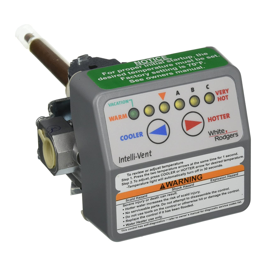
- Page 3 INTELLI-VENT TROUBLESHOOTING GUIDE INTELLI-VENT™ CONSTRUCTION 6 LED indicator lights Temperature Probe/ECO • Temperature Settings • Error Codes / Diagnostics Supply Gas Connection Temperature adjust buttons Future side connect model is Temperature adjust buttons shown here. Top connect models must be pressed together for are in use currently.
- Page 4 INTELLI-VENT TROUBLESHOOTING GUIDE INTELLI-VENT™ OPERATION 6 LED indicator lights • Temperature Settings • Error Codes / Diagnostics Temperature adjust buttons PRE START UP CHECK LIST • Correct polarity on electrical supply • Water heater is properly grounded • Owner’s manual safety statements have been reviewed START UP PROCEDURE 1 Plug in water heater and turn on power.
- Page 5 INTELLI-VENT TROUBLESHOOTING GUIDE TEMPERATURE SETTINGS Residential and commercial Intelli-Vent controls differ in appearance: • The far left LED light is green on the residential control and the remaining 5 LEDs are yellow. • On the commercial control all six LEDs are yellow.
- Page 6 INTELLI-VENT TROUBLESHOOTING GUIDE INTELLI-VENT™ SPECIFICATIONS INTELLI-VENT™ CONTROL SPECIFICATIONS Body ½ inch NPT inlet. ½ inch inverted flare outlet. (RH thread natural, LH thread propane) Electrical Ratings 120 VAC, 60 Hz, 1Ø, 5-7 FLA. Ignitor load: 2 amps maximum. Blower/inducer motors: 3 amps full load - 4 amps locked rotor.
- Page 7 6. = 120 VAC Neutral Wire to Control There are two female Molex plug receptacles on the bottom of the Intelli-Vent™ control. Keep in mind the receptacles (female) and plugs (male) are mirror images of each other in regard to pin number location and retaining clip orientation.
- Page 8 INTELLI-VENT TROUBLESHOOTING GUIDE Technical Training Department Ashland City, Tennessee © 2005 7 of 24...
- Page 9 INTELLI-VENT TROUBLESHOOTING GUIDE INTELLI-VENT™ SEQUENCE OF OPERATION Technical Training Department Ashland City, Tennessee © 2005 8 of 24...
- Page 10 1 Always turn power off for 10 to 20 seconds and then back on again to clear an error code before replacing an Intelli-Vent™ control. 2 When installing the water heater or a replacement Intelli-Vent™ control, do not use the control face as a handle to move the water heater or turn (thread) the control.
- Page 11 Insure all internal 120 VAC wiring connections on the water heater are not reversed. 120 VAC “hot” wire should connect to the on/off switch. • Insure the wiring harness between the Intelli-Vent control and the wiring box has no crossed wires with an ohm meter. (see 7) •...
- Page 12 Check / Repair: • Insure the blower is starting and coming up to speed, if the Intelli-Vent control will not energize the blower with the air pressure switch circuit open, replace the Intelli-Vent control (see footnote page10).
- Page 13 • Check all wiring to the hot surface ignitor. • Check 5 pin Molex ignitor assembly plug and receptacle on the Intelli-Vent™ body for a good connection. Repair or replace parts if necessary. • Check resistance of ignitor with an ohm meter between pin 1 and 2 on the ignitor assembly plug.
- Page 14 Turn the power off for 10-20 seconds then on again to clear these error codes. • If any of these error codes persist or cannot be cleared - replace the Intelli-Vent™ control. ERROR CODE 10 - FLAME SENSED OUT OF SEQUENCE Flame signal has been sensed out of proper sequence.
- Page 15 Turn the power off for 10-20 seconds then on again to clear this error code. • This part of the control cannot be replaced or serviced. If the error code cannot be cleared, the Intelli-Vent™ control must be replaced. Technical Training Department Ashland City, Tennessee © 2005...
- Page 16 3 & 4 with an ohm meter. A If the reading taken is more than 50,000 ohms replace the ignitor assembly. B If the reading taken is less than 50,000 ohms replace the Intelli-Vent™ control. Technical Training Department Ashland City, Tennessee ©...
- Page 17 FLAME SENSOR ALIGNMENT (Intelli-Vent™ equipped - standard recovery - 40 & 50 gallon residential water heaters) The lower lip or edge of a low NOx burner extends out further than it does on a standard burner.
- Page 18 INTELLI-VENT TROUBLESHOOTING GUIDE FLAME SENSOR ALIGNMENT (CONT) Technical Training Department Ashland City, Tennessee © 2005 17 of 24...
- Page 19 2 Ignitor assembly plug connection. Check the 5 pin Molex plug and the female receptacle in the control body to insure all conductors are present and making good contact. Wiggle both Molex plugs at the control body to check for poor connections if the Intelli-Vent control is not responding for any reason.
- Page 20 This can cause air turbulence inside the combustion chamber that leads to: 1 Fuel gas being swept away from the ignitor leading to ignition failure (failure to ignite). The Intelli-Vent control would lockout after 3 failed attempts and display error code 6.
- Page 21 INTELLI-VENT TROUBLESHOOTING GUIDE TECHNICAL BULLETIN - AIR PRESSURE SWITCHES A-023-04 & S-024-04 COMBINED Air pressure switches are used on all fan assisted gas fired water heaters, residential and commercial. If the water heater was factory equipped with a combustion blower or inducer fan, by design the blower must running during the heating cycle.
- Page 22 INTELLI-VENT TROUBLESHOOTING GUIDE AIR PRESSURE SWITCH CONSTRUCTION The switch below has normally open switch contacts that close on a fall in pressure. Normal State Activated State Wiring terminals Sensing port Switch contacts Diaphragm Vent port AIR PRESSURE SWITCH OPERATION Air pressure switches activate in response to changes in air pressure sensed through a plastic tube attached to a sensing port on the water vent system and/or blower housing.
- Page 23 INTELLI-VENT TROUBLESHOOTING GUIDE AIR PRESSURE SWITCHES - DIFFERENT TYPES SWITCH CONTACTS SWITCH ACTION Normally Open = NO Close on a rise in pressure Close on a fall in pressure Normally Closed = NC Open on a rise in pressure Open on a fall in pressure The switches shown here are all SPST switches.
- Page 24 INTELLI-VENT TROUBLESHOOTING GUIDE AIR PRESSURE SWITCH TESTING Continuity test with ohm meter Taking an air pressure reading To test the performance of an air pressure switch you must know the design activation point. This will be a given pressure value, either negative (in a vacuum) or a positive pressure.
- Page 25 INTELLI-VENT TROUBLESHOOTING GUIDE AIR PRESSURE SWITCH CIRCUITS Air Pressure Switch Circuit - Residential Power Vent/Power Direct Vent Blocked Exhaust Switch Vent Temperature Limit Switch Normally Open Contacts Normally Closed Contacts Close on a Fall in Pressure Open on a Rise in Temperature...
- Page 26 No.: ARGPN0305N Date: March 18, 2005 Vent Termination Restrictor Usage for 40,000 Btu Power Vent Models This bulletin will simplify vent termination restrictor usage for the 40,000 Btu power vent models and allowable venting distances. Power vent models, 40,000 Btu, manufactured prior to November 2004 (serial number K04) are shipped with a vent kit that includes a 2"...
- Page 27 No.: S425 Date: 10/21/04 Vent Termination Restrictor Usage for 40,000 Btu Power Vent Models This bulletin will simplify vent termination restrictor usage for the 40,000 Btu power vent models and allowable venting distances. Power vent models, 40,000 Btu, manufactured prior to November 2004 (serial number K04) are shipped with a vent kit that includes a 2"...
- Page 28 Additional copies are available from the Ashland City Advertising Department Prepared by the A. O. Smith/State Water Heater Technical Training Department Ashland City, Tennessee...
- Page 29 TB-A028-06 - A. O. SMITH - FVIR INTELLI-VENT TROUBLESHOOTING CHART LED STATUS PROBLEM SOLUTION Inadequate or no earth ground 1 Ensure the wall outlet is properly grounded. sensed by the Intelli-Vent™ 2 Ensure all ground connections/wires on the water control.
- Page 30 TB-A028-06 - A. O. SMITH - FVIR INTELLI-VENT TROUBLESHOOTING CHART LED STATUS PROBLEM SOLUTION Ignition/flame failure. 1 Gas supply is turned off - pressure too low. Ensure supply and manifold gas pressures are within The water heater has reached requirements in the installation manual. Manifold gas...
- Page 31 TB-A028-06 - A. O. SMITH - FVIR INTELLI-VENT TROUBLESHOOTING CHART LED STATUS PROBLEM SOLUTION The self diagnostic test has 1 Turn off power to the water heater. Ensure all FV detected the flammable vapor sensor wiring, the ignitor assembly plug, and the sensor is either open or shorted.
- Page 32 TB-A028-06 - A. O. SMITH - FVIR INTELLI-VENT TROUBLESHOOTING CHART LED STATUS PROBLEM SOLUTION The self diagnostic test has 1 Turn off power to the water heater. Carefully check detected the presence of the surrounding area for any substances such as flammable vapors.
- Page 33 Additional Recommended Service Publications • Power-Vent service manual - part number TC-048 R6 (revision 6 or later) • Intelli-Vent™ service manual supplement - part number GTC-070 R3 (revision 3 or later) • Air Pressure Switches technical bulletin - number TB-A023-06 Visit our web site at www.hotwater.com to download the above service manual and supplement.
- Page 35 Tuesday, January 16, 2007 Technical Bulletin TB-A023-06 Air Pressure Switches This bulletin has been prepared to explain and illustrate the construction, operation, and testing procedures for various types of air pressure switches used on residential and commercial tank type water heaters. Air pressure switches are used on all “fan assisted”...
- Page 36 Air Pressure Switch Construction Normal State Activated State (open switch contacts) (closed switch contacts) Wiring Terminals Sensing Port Switch Contacts Internal Linkage Flexible Diaphragm Vent Port Air Pressure Switch Operation Air pressure switches activate in response to pressure sensed through a tube. One end of this tube attaches to the pressure switch sensing port, the other end attaches to a pressure sensing port somewhere on the water heater, IE: the vent system, blower assembly.
- Page 37 Air Pressure Switch Operation (cont) Contact Actions: The “action” of the contacts refers to what causes the switch to activate, to change from it’s “normal state” to its “activated state” (see page 2). On an air pressure switch this can be either a rise or fall in pressure.
- Page 38 Air Pressure Switch Testing Continuity Test With Ohm Meter Continuity Test With Ohm Meter BTH 120 - 250 Blocked Exhaust Switch Power-Vent Residential Model Testing the performance of air pressure switches involves three procedures. First Procedure is a normal state test to determine if the switch contacts are open or closed in the normal state (see page 2) without pressure applied.
- Page 39 Air Pressure Switch Testing (cont) The pressure activation point for the air pressure switch below is - 1.07" W. C. (inches water column) This is a negative pressure value – in a vacuum. Blocked Vent Air Pressure Switch Blocked Vent Switch - Pressure Test Residential Power Vent Model Vertex Residential Power Vent Model Third Procedure...
- Page 40 Blocked Exhaust Switch Pressure Test Blocked Exhaust Switch Pressure Test Cyclone - BTH 300/400 Models Cyclone - BTH 120 - 250 Models Air Pressure Switch Testing Third Procedure - Normally Open Switches (cont): Pressure reading taken DOES NOT reach the activation pressure (cont): Ensure the sensing tube is connected securely and not blocked with any debris or condensate.
- Page 41 Air Pressure Switch Types Contact States Contact Actions Close on a rise in pressure Normally Open = NO Close on a fall in pressure Normally Closed = NC Open on a rise in pressure Open on a fall in pressure Application Normal State Activated State...
- Page 42 Air Pressure Switch Circuit Residential Power-Vent & Power-Direct-Vent Water Heaters Blocked Exhaust Switch Vent Temperature Limit Switch Normally Open Contacts Normally Closed Contacts Close on a Fall in Pressure Open on a Rise in Temperature Molex Plug 6 Pin Plug Air Pressure Switch Circuit Cyclone Water Heater Blocked Inlet Switch...
- Page 43 Intelli-Vent™ Sequence of Operation...
Need help?
Do you have a question about the INTELLI-VENT and is the answer not in the manual?
Questions and answers