Table of Contents
Advertisement
Quick Links
Download this manual
See also:
Operator's Manual
Advertisement
Chapters
Table of Contents

Related Manuals for Esterline CMA-9000

Summary of Contents for Esterline CMA-9000
- Page 1 DRAFT OPERATOR'S MANUAL FLIGHT MANAGEMENT SYSTEM CMA-9000 OPERATIONAL PROGRAM S/W 169-614876-050-RRJ Esterline CMC Electronics 600 Dr. Frederik Philips Boulevard Ville Saint-Laurent, Quebec, Canada H4M 2S9...
- Page 2 DRAFT OPERATOR'S MANUAL FLIGHT MANAGEMENT SYSTEM CMA-9000 OPERATIONAL PROGRAM S/W 169-614876-050-RRJ Esterline CMC Electronics 600 Dr. Frederik Philips Boulevard Ville Saint-Laurent, Quebec, Canada H4M 2S9 Publication No. 9000-GEN-0137 August 17, 2010 Item No.: 930-600139-000...
- Page 3 DRAFT This Page Intentionally Left Blank...
- Page 4 DRAFT WE VALUE YOUR COMMENTS PLEASE EVALUATE OUR PUBLICATION AND LET US KNOW Although we constantly strive for accuracy and clarity, we may make errors on occasion. If we do, we would appreciate your comments to improve this manual. Please following Customer Comments...
- Page 5 DRAFT This Page Intentionally Left Blank...
- Page 6 DRAFT CUSTOMER COMMENTS PUBLICATION TITLE: MANUAL P/N: DATE OF ISSUE: REVISION DATE: COMMENTS: PAGE PARA- LINE FIGURE TABLE CHANGE AND REASON GRAPH NAME: POSITION: TELEPHONE: E-MAIL ADDRESS: COMPANY'S NAME & ADDRESS:...
- Page 7 DRAFT From:______________________________ PLACE POSTAGE HERE CMC Electronics Inc. CUSTOMER SUPPORT 600 DR. FREDERIK PHILIPS BOULEVARD VILLE ST. LAURENT, QUEBEC, CANADA H4M 2S9 FOLD BACK ………………………………………………………………………………………............................
-
Page 8: Subject Page
DRAFT OPERATOR’S MANUAL CMA-9000 FLIGHT MANAGEMENT SYSTEM LIST OF EFFECTIVE PAGES NOTE The portion of the text affected by the latest change is indicated by a vertical line in the margin of the page. Changes to illustrations are indicated by miniature pointing hands or black vertical lines. - Page 9 Aug 17/10 1-10 Aug 17/10 1-11 Aug 17/10 1-12 Aug 17/10 1-13 Aug 17/10 1-14 Blank 2 - CMA-9000 FMS Control and Display Aug 17/10 2-ii Blank Aug 17/10 Aug 17/10 Aug 17/10 Aug 17/10 Aug 17/10 Aug 17/10 Aug 17/10...
- Page 10 DRAFT OPERATOR’S MANUAL CMA-9000 FLIGHT MANAGEMENT SYSTEM SUBJECT PAGE DATE 3 - Preflight (cont’d) 3-18 Aug 17/10 3-19 Aug 17/10 3-20 Aug 17/10 3-21 Aug 17/10 3-22 Blank 4 - Departures Aug 17/10 4-ii Blank Aug 17/10 Aug 17/10 Aug 17/10...
- Page 11 DRAFT OPERATOR’S MANUAL CMA-9000 FLIGHT MANAGEMENT SYSTEM SUBJECT PAGE DATE 5 - Enroute (cont’d) 5-33 Aug 17/10 5-34 Aug 17/10 5-35 Aug 17/10 5-36 Aug 17/10 6 - Arrivals Aug 17/10 6-ii Blank Aug 17/10 Aug 17/10 Aug 17/10 Aug 17/10...
- Page 12 Aug 17/10 12-6 Aug 17/10 12-7 Aug 17/10 12-8 Aug 17/10 12-9 Aug 17/10 12-10 Aug 17/10 13 -CMA-9000 FMS Pages - Radio Tuning 13-i Aug 17/10 13-ii Aug 17/10 13-1 Aug 17/10 13-2 Aug 17/10 13-3 Aug 17/10 13-4...
- Page 13 DRAFT OPERATOR’S MANUAL CMA-9000 FLIGHT MANAGEMENT SYSTEM SUBJECT PAGE DATE 13 -CMA-9000 FMS Pages - Radio Tuning (cont’d) 13-10 Aug 17/10 13-11 Aug 17/10 13-12 Aug 17/10 13-13 Aug 17/10 13-14 Aug 17/10 13-15 Aug 17/10 13-16 Aug 17/10 13-17...
-
Page 14: Ii Aug
DRAFT OPERATOR’S MANUAL CMA-9000 FLIGHT MANAGEMENT SYSTEM SUBJECT PAGE DATE Appendix A - CMA-9000 FMS Display Pages - Detailed Descriptions Aug 17/10 A-ii Aug 17/10 Aug 17/10 Aug 17/10 Aug 17/10 Aug 17/10 Aug 17/10 Aug 17/10 Aug 17/10 Aug 17/10... - Page 15 DRAFT OPERATOR’S MANUAL CMA-9000 FLIGHT MANAGEMENT SYSTEM SUBJECT PAGE DATE Appendix A - CMA-9000 FMS Display Pages - Detailed Descriptions (cont’d) A-49 Aug 17/10 A-50 Aug 17/10 A-51 Aug 17/10 A-52 Aug 17/10 A-53 Aug 17/10 A-54 Aug 17/10 A-55...
- Page 16 DRAFT OPERATOR’S MANUAL CMA-9000 FLIGHT MANAGEMENT SYSTEM SUBJECT PAGE DATE Appendix A - CMA-9000 VNAV RRJ Display Pages - Detailed Descriptions RRJ-A-i Aug 17/10 RRJ-A-ii Blank RRJ-A-1 Aug 17/10 RRJ-A-2 Aug 17/10 RRJ-A-3 Aug 17/10 RRJ-A-4 Aug 17/10 RRJ-A-5 Aug 17/10...
- Page 17 DRAFT OPERATOR’S MANUAL CMA-9000 FLIGHT MANAGEMENT SYSTEM SUBJECT PAGE DATE Appendix A - CMA-9000 VNAV RRJ Display Pages - Detailed Descriptions (cont’d) RRJ-A-49 Aug 17/10 RRJ-A-50 Aug 17/10 RRJ-A-51 Aug 17/10 RRJ-A-52 Aug 17/10 RRJ-A-53 Aug 17/10 RRJ-A-54 Aug 17/10...
- Page 18 SUBJECT PAGE DATE Appendix C - Navigation Displays – EFIS (cont’d) Aug 17/10 Aug 17/10 Aug 17/10 C-10 Blank Appendix D - CMA-9000 FMS Display Pages Flow Diagrams Aug 17/10 D-ii Blank Aug 17/10 Blank Aug 17/10 Blank Aug 17/10...
- Page 19 E-24 Aug 17/10 E-25 Aug 17/10 E-26 Aug 17/10 E-27 Aug 17/10 E-28 Aug 17/10 Appendix F - CMA-9000 FMS RRJ VNAV Aug 17/10 F-ii Aug 17/10 Aug 17/10 Aug 17/10 Aug 17/10 Aug 17/10 Aug 17/10 Aug 17/10 Aug 17/10...
- Page 20 DRAFT OPERATOR’S MANUAL CMA-9000 FLIGHT MANAGEMENT SYSTEM SUBJECT PAGE DATE Appendix F - CMA-9000 FMS RRJ VNAV (cont’d) F-39 Aug 17/10 F-40 Aug 17/10 F-41 Aug 17/10 F-42 Aug 17/10 F-43 Aug 17/10 F-44 Aug 17/10 F-45 Aug 17/10 F-46...
- Page 21 DRAFT OPERATOR’S MANUAL CMA-9000 FLIGHT MANAGEMENT SYSTEM This Page Intentionally Left Blank Page LEP-14 August 17, 2010...
- Page 22 DRAFT OPERATOR’S MANUAL CMA-9000 FLIGHT MANAGEMENT SYSTEM On receipt of revisions, insert pages and record RECORD OF REVISIONS date inserted and initial. ASSIGNED TO (JOB TITLE) LOCATION REV. REVISION INSERTION REV. REVISION INSERTION DATE DATE DATE DATE Page RR-1 August 17, 2010...
- Page 23 DRAFT OPERATOR’S MANUAL CMA-9000 FLIGHT MANAGEMENT SYSTEM This Page Intentionally Left Blank Page RR-2 August 17, 2010...
-
Page 24: Fms Display Pages Flow Diagrams (Sheet 1
Section 8 Direct-To/Intercept Section 9 Holding Pattern Navigation Section 10 Tactical Functions Section 11 Navigation Sensors Section 12 CMA-9000 FMS Pages - Radio Tuning Section 13 Performance Functions Section 14 RNP Capability Section 15 MCDU Functions Section 16 Abnormal Procedures... - Page 25 DRAFT OPERATOR’S MANUAL CMA-9000 FLIGHT MANAGEMENT SYSTEM This Page Intentionally Left Blank Page TC-2 August 17, 2010...
- Page 26 THIS MANUAL IS INTENDED TO BE A GENERIC MANUAL FOR ALL FMS APPLICATIONS. PROCEDURES DESCRIBED HEREIN INCLUDE ALL THE AVAILABLE DISPLAYS AND CONTROLS. When the CMA-9000 FMS is set up through the configuration procedures, as described in the installation manual, some of the features described herein may be disabled and not displayed.
- Page 27 AND LIMITATIONS OPERATIONAL APPROVAL Approval of the CMA-9000 FMS for VFR/IFR operation must be obtained from the Civil Aviation Authority of the country of registration of the aircraft. When operated with any of the external GPS equipment listed in Figure 5B Approved Installation Configurations with GPS Equipment of the Installation Flight Line Manual, the CMA-9000 FMS has been approved for VFR/IFR GPS supplemental navigation in en-route, terminal and non-precision approach.
-
Page 28: Table Of Contents
DRAFT OPERATOR’S MANUAL CMA-9000 FLIGHT MANAGEMENT SYSTEM SECTION 1 - INTRODUCTION CONTENTS Subject Page SYSTEM OVERVIEW ............................1-1 COMPONENT DESCRIPTION ..........................1-2 A. Flight Management System (FMS) with Embedded Display Unit............1-2 B. External Global Positioning System (GPS) Receiver................1-2 NAVIGATION MODES ............................1-3 A. GPS................................1-3 B. - Page 29 DRAFT OPERATOR’S MANUAL CMA-9000 FLIGHT MANAGEMENT SYSTEM This Page Intentionally Left Blank Page 1-ii August 17, 2010...
-
Page 30: System Overview
FMS with information on waypoints, navaids, airports, terminal area procedures, airways... In addition the database is capable of storing customer defined routes and waypoints. The CMA-9000 also integrates the functionality of Radio Management System (RMS) and Multi-Function Control Display Unit (MCDU) into a standalone, cockpit mounted enclosure. -
Page 31: Component Description
COMPONENT DESCRIPTION A. Flight Management System (FMS) with Embedded Display Unit The CMA-9000 provides a color display of alphanumeric data. An alphanumeric keyboard allows data entry, data editing and system control of the flight management functions. The display is a sunlight readable color Active Matrix Liquid Crystal Display (AMLCD). Dedicated function keys and line select keys allow easy operator control of flight management functions. -
Page 32: Navigation Modes
DRAFT OPERATOR’S MANUAL CMA-9000 FLIGHT MANAGEMENT SYSTEM NAVIGATION MODES The FMS follows a hierarchical navigation mode system using TSO-approved sensors characterized by the following decreasing priority order: Navigation modes Sensor TSO-C129a B1/C1 GPS sensor DME/DME TSO-C66c DME receiver VOR/DME TSO-C66c DME receiver;... -
Page 33: Inertial
DRAFT OPERATOR’S MANUAL CMA-9000 FLIGHT MANAGEMENT SYSTEM D. Inertial The FMS inertial navigation mode is based on the following parameters: • Present Position Latitude and Longitude; • North-South velocity; • East-West velocity. The FMS uses the raw Inertial position and velocities provided by the IRS. -
Page 34: Waypoint Navigation
DRAFT OPERATOR’S MANUAL CMA-9000 FLIGHT MANAGEMENT SYSTEM WAYPOINT NAVIGATION The FMS navigates from waypoint to waypoint sequentially, automatically changing the legs, and displays all required navigation parameters, computed according to the relationships and direction sense illustrated in Figure 1-1. NORTH... -
Page 35: Terminal Area Operations And Gps Instrument Approaches
DRAFT OPERATOR’S MANUAL CMA-9000 FLIGHT MANAGEMENT SYSTEM The FMS steering function anticipates the next leg prior to reaching the active (TO) waypoint so that the aircraft turns are smooth without any overshoot. Waypoints may be defined as either fly-by (with turn anticipation) or fly-over (no turn anticipation). -
Page 36: Acronyms And Abbreviations
DRAFT OPERATOR’S MANUAL CMA-9000 FLIGHT MANAGEMENT SYSTEM ACRONYMS AND ABBREVIATIONS Above (altitude) Air-To-Air AAIM Aircraft Autonomous Integrity Monitoring Aircraft ACCUR Accuracy ACID Aircraft Identifier Active ACMS Aircraft Conditioning Monitoring System Acquisition mode Air Data Computer Automatic Direction Finder ADIRS Air Data Inertial Reference System... - Page 37 DRAFT OPERATOR’S MANUAL CMA-9000 FLIGHT MANAGEMENT SYSTEM Clear Primary (CM1) or Secondary (CM2) COM radio Canadian Marconi (Avionics) Command Communications Management Unit Communication COMMS Communication Radios Connection CONC Concentrator COORD Coordinates Compass Computed Air Release Point Course (desired track) of route leg or to waypoint...
- Page 38 DRAFT OPERATOR’S MANUAL CMA-9000 FLIGHT MANAGEMENT SYSTEM EXEC Execute Final Approach Fix Failure Detection and Exclusion Final Approach Fix Front panel Function Key Flight Level Flight Flight Management System Flight Management Unit First Officer Figure of Merit Floating Point Unit...
- Page 39 DRAFT OPERATOR’S MANUAL CMA-9000 FLIGHT MANAGEMENT SYSTEM Instrument Flight Rules in Hg Inches of Mercury Instrument Landing System Innner Marker INBD Inbound INACT Inactive INIT Initialize Integrity INTC Intercept Course Inertial Navigation System Identification Point Inertial Reference System Telecommunication Union...
- Page 40 DRAFT OPERATOR’S MANUAL CMA-9000 FLIGHT MANAGEMENT SYSTEM MSLA Mean Sea Level Altitude MTBF Mean Time Between Failures North NAV radio (primary : N1, secondary : N2) Navigation or Navaid Non-directional Beacon NDBD NDB approach with DME facility (GPS or NDB/(DME))
- Page 41 DRAFT OPERATOR’S MANUAL CMA-9000 FLIGHT MANAGEMENT SYSTEM Receive only Flight Recorder Reference Relative Reserve RESEL Reselect Radio Frequency Radio Interface Board Radio Management System RNAV Required Navigation Range Required Navigation Performance Required Time of Arrival Real Time Clock Route Runway Threshold...
- Page 42 DRAFT OPERATOR’S MANUAL CMA-9000 FLIGHT MANAGEMENT SYSTEM TOGA Take-Off/Go-Around Turn Point TPDR Transponder Transmit/Receive TRANS Transition Track Transmit on Guard Total System Error Technical Standard Order TTFF Time To First Fix Time To Go Time To Station V/UHF1 Transmitting V/UHF2 Transmitting...
- Page 43 DRAFT OPERATOR’S MANUAL CMA-9000 FLIGHT MANAGEMENT SYSTEM This Page Intentionally Left Blank Page 1-14 August 17, 2010...
- Page 44 DRAFT OPERATOR’S MANUAL CMA-9000 FLIGHT MANAGEMENT SYSTEM SECTION 2 - CONTROL AND DISPLAY CONTENTS Subject Page GENERAL ...............................2-1 FMCDU FRONT PANEL ..........................2-1 GENERAL RULES OF DISPLAY OPERATION.....................2-7 WAYPOINT NAMES AND OTHER CONVENTIONS ...................2-10 Page 2-i August 17, 2010...
- Page 45 DRAFT OPERATOR’S MANUAL CMA-9000 FLIGHT MANAGEMENT SYSTEM This Page Intentionally Left Blank Page 2-ii August 17, 2010...
-
Page 46: General
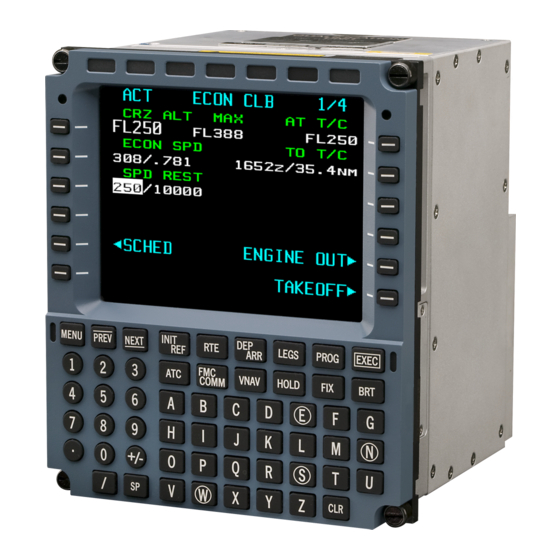
CONTROL AND DISPLAY GENERAL The CMA-9000 FMS is a Flight Management Computer (FMC) embedded within a Multipurpose Control Display Unit (MCDU), thus becoming an FMCDU. The MCDU function can be interfaced with up to seven other ARINC- 739 capable LRUs (ACARS, SATCOM, ACMS,…). The display section of the MCDU is a color Active Matrix Liquid Crystal Display (AMLCD) providing fourteen lines of twenty-four characters. - Page 47 DRAFT OPERATOR’S MANUAL CMA-9000 FLIGHT MANAGEMENT SYSTEM Figure 2-1 FMS Front Panel, Hardware variation 045/445 Page 2-2 August 17, 2010...
- Page 48 DRAFT OPERATOR’S MANUAL CMA-9000 FLIGHT MANAGEMENT SYSTEM The item numbers 1 to 33 below refer to the annunciators and keys in Figure 2-1 and all subsequent figures. Display Screen - Item 1: Provides 14 lines of 24 characters. Line 1 is always used for the page title & page number. Line 2 to 13 is always used for data. Line 14 is always used for the scratchpad entry.
- Page 49 DRAFT OPERATOR’S MANUAL CMA-9000 FLIGHT MANAGEMENT SYSTEM In brief, the color convention for the STANDARD configuration is as follows: Items Font Color Page Title Large Cyan Active waypoint Large Reverse video magenta Page prompt (with outward triangle) Large Cyan Legs page waypoint...
- Page 50 DRAFT OPERATOR’S MANUAL CMA-9000 FLIGHT MANAGEMENT SYSTEM NOTE: The annunciator layout depends on the selected Front Panel hardware variation (refer to Table 1). Also, individual annunciators may be enabled/disabled via dedicated configuration options. Front Panel Position 2 Position 3 Position 4...
- Page 51 DRAFT OPERATOR’S MANUAL CMA-9000 FLIGHT MANAGEMENT SYSTEM 27. Decimal (.) Key - provides decimal point for numeric data entries. 28. Alpha-Numeric Keyboard - allows entry of alpha-numeric data. 29. NEXT Key - when multiple-page displays are indicated in the page title line, pressing the NEXT key advances the display to the next higher page number or to page 1 if presently on the last page.
-
Page 52: General Rules Of Display Operation
DRAFT OPERATOR’S MANUAL CMA-9000 FLIGHT MANAGEMENT SYSTEM GENERAL RULES OF DISPLAY OPERATION The operating procedures detailed in the following sections are governed by a general set of FMS operation rules. Familiarity with these rules will greatly simplify the process of learning system operation. - Page 53 DRAFT OPERATOR’S MANUAL CMA-9000 FLIGHT MANAGEMENT SYSTEM Page Title - the name of the page is shown on the top line of the display. Page Number - when a display consists of several pages (as indicated in the upper right of the page), the additional pages may be displayed by pressing the NEXT or PREV keys.
- Page 54 DRAFT OPERATOR’S MANUAL CMA-9000 FLIGHT MANAGEMENT SYSTEM Data Entry • Entry error advisory messages are identified in the scratchpad by a leading "!". Both the MESSAGE RECALL page and the MAINT MESSAGES page can be accessed via the [INIT REF] key, via the MSG key or by pressing and holding the[ INIT REF] key for more than 1 second.
-
Page 55: Waypoint Names And Other Conventions
DRAFT OPERATOR’S MANUAL CMA-9000 FLIGHT MANAGEMENT SYSTEM WAYPOINT NAMES AND OTHER CONVENTIONS Terminal Area Waypoints - where specific identifiers have not been assigned, the following two-character prefix codes are added to the runway identifier (number) to create terminal area and approach-related waypoints... - Page 56 DRAFT OPERATOR’S MANUAL CMA-9000 FLIGHT MANAGEMENT SYSTEM Course Legends - courses may be displayed with the following legends depending on the leg type, as listed below: Indicates a course leg inbound to the next waypoint FR FIX Indicates a course outbound from the FIX...
- Page 57 DRAFT OPERATOR’S MANUAL CMA-9000 FLIGHT MANAGEMENT SYSTEM This Page Intentionally Left Blank Page 2-12 August 17, 2010...
- Page 58 DRAFT OPERATOR’S MANUAL CMA-9000 FLIGHT MANAGEMENT SYSTEM SECTION 3 - PREFLIGHT CONTENTS Subject Page CONDENSED PREFLIGHT PROCESS......................3-1 PREFLIGHT..............................3-2 START-UP AND INITIALIZATION........................3-3 ACTIVE DATABASE SELECTION.........................3-4 FMS DISPLAY SETUP............................3-5 SYSTEM POSITION, DATE AND TIME UPDATE..................3-6 ANGULAR REFERENCES FOR NAVIGATION AND DISPLAY ..............3-7 ACTIVE ROUTE SELECTION USING THE CUSTOM ROUTE NAME............3-9...
- Page 59 DRAFT OPERATOR’S MANUAL CMA-9000 FLIGHT MANAGEMENT SYSTEM This Page Intentionally Left Blank Page 3-ii August 17, 2010...
-
Page 60: Condensed Preflight Process
DRAFT OPERATOR’S MANUAL CMA-9000 FLIGHT MANAGEMENT SYSTEM SECTION 3 PREFLIGHT CONDENSED PREFLIGHT PROCESS This page sequence gives an overview of the Preflight operations of the FMS. The intent of each step is summarized on the next page. If radios are used... -
Page 61: Preflight
DRAFT OPERATOR’S MANUAL CMA-9000 FLIGHT MANAGEMENT SYSTEM PREFLIGHT 1. IDENT - check software version number. Check Configuration Number. Check active database date and interchange if necessary. 2. POS INIT/REF – If GPS is available, check aircraft present position, time and date. Otherwise, manually enter the system and/or IRS position (for alignment). -
Page 62: Start-Up And Initialization
DRAFT OPERATOR’S MANUAL CMA-9000 FLIGHT MANAGEMENT SYSTEM START-UP AND INITIALIZATION 1. Verify that all relevant circuit breakers are on. 2. Upon initial power-up, the FMS will test all the annunciators. After these tests, it displays the IDENT 1/2 page as the default power-up page. -
Page 63: Active Database Selection
DRAFT OPERATOR’S MANUAL CMA-9000 FLIGHT MANAGEMENT SYSTEM ACTIVE DATABASE SELECTION CAUTION: When the active database is changed, any existing active route is deleted. 1. Copy the SECOND cycle date into the scratchpad, by pressing LSK 2R. 2. Move the cycle date into the ACTIVE field by pressing LSK 1R. -
Page 64: Fms Display Setup
DRAFT OPERATOR’S MANUAL CMA-9000 FLIGHT MANAGEMENT SYSTEM FMS DISPLAY SETUP From the IDENT 1/2 page, go to DISPLAY 1/1 page, by pressing [INIT REF] and <DISPLAY> (LSK 4L). DISPLAY <PARALLAX <INIT/REF 1. Press LSK 1L and adjust display PARALLAX for proper viewing angle. -
Page 65: System Position, Date And Time Update
DRAFT OPERATOR’S MANUAL CMA-9000 FLIGHT MANAGEMENT SYSTEM SYSTEM POSITION, DATE AND TIME UPDATE From the IDENT 1/2 page go to POS INIT/REF 1/3 page by pressing <POS INIT> (LSK 6R). POS INIT/REF F M S P O S G P S 26.28 W122... -
Page 66: Angular References For Navigation And Display
DRAFT OPERATOR’S MANUAL CMA-9000 FLIGHT MANAGEMENT SYSTEM To initialize the position use the POS INIT/REF 1/3 page: POS INIT/REF F M S P O S G P S 26.28 W122 18.67 R E F A I R P O R T KLAX N47 26.28 W122... - Page 67 DRAFT OPERATOR’S MANUAL CMA-9000 FLIGHT MANAGEMENT SYSTEM The angle display reference DISPLAY (TRUE or MAGNETIC) is controlled via an external true/mag cockpit switch. CAUTION: For those installations where the FMS is the only source of magnetic information, it is possible to configure the FMS to prevent invalidation of magnetic angles in high latitude regions.
-
Page 68: Active Route Selection Using The Custom Route Name
DRAFT OPERATOR’S MANUAL CMA-9000 FLIGHT MANAGEMENT SYSTEM ACTIVE ROUTE SELECTION USING THE CUSTOM ROUTE NAME Display the RTE 1/X page by pressing the [RTE] function key. RTE 1 O R I G I N D E S T KSEA PANC... -
Page 69: Route Selection From The List Of Custom Routes
DRAFT OPERATOR’S MANUAL CMA-9000 FLIGHT MANAGEMENT SYSTEM ROUTE SELECTION FROM THE LIST OF CUSTOM ROUTES With the ACT or MOD RTE 1/X page displayed: Display the custom routes by pressing <CO ROUTES> (LSK 4R). SELECT CO ROUTE KSEAPANC KSEAPANC1 KSEAPANC2 L O A D >DIRECT... -
Page 70: Active Route Selection Using The User Route Name
DRAFT OPERATOR’S MANUAL CMA-9000 FLIGHT MANAGEMENT SYSTEM ACTIVE ROUTE SELECTION USING THE USER ROUTE NAME Display the RTE 1/X page by pressing the RTE function key. RTE 1 O R I G I N D E S T KSEA PANC... -
Page 71: Route Selection From The List Of User Routes
DRAFT OPERATOR’S MANUAL CMA-9000 FLIGHT MANAGEMENT SYSTEM ROUTE SELECTION FROM THE LIST OF USER ROUTES With the ACT or MOD RTE 1/X page displayed: Display the user routes by pressing <USER ROUTES> (LSK 5R). USER ROUTES 0 0 0 1 M 0 0 0 9 M... -
Page 72: Building A Route Via Waypoint Insertion
DRAFT OPERATOR’S MANUAL CMA-9000 FLIGHT MANAGEMENT SYSTEM BUILDING A ROUTE VIA WAYPOINT INSERTION When no custom route is available, a route can be created by first defining the origin and destination airports on the ROUTE page, followed by entry of the individual waypoints on the RTE x LEGS page. -
Page 73: Building A Route Via Airway Insertion
DRAFT OPERATOR’S MANUAL CMA-9000 FLIGHT MANAGEMENT SYSTEM BUILDING A ROUTE VIA AIRWAY INSERTION When no custom route is available, a route can be created by first defining the origin and destination airports on the ROUTE page, followed by entry of the individual airway identifier on the ROUTE page. -
Page 74: Building A Departure Procedure
DRAFT OPERATOR’S MANUAL CMA-9000 FLIGHT MANAGEMENT SYSTEM NOTE: The route structure can be modified by defining the waypoint identifier at which the desired airway is terminated and repeating the procedure for entering the following airways. If a departure or an arrival is selected on the DEP/ARR page, the procedure and the transition name will be displayed in the VIA and TO fields. -
Page 75: Verifying Active Route Legs By Course And Distance
DRAFT OPERATOR’S MANUAL CMA-9000 FLIGHT MANAGEMENT SYSTEM VERIFYING ACTIVE ROUTE LEGS BY COURSE AND DISTANCE Display the MOD RTE x LEGS 1/X page by pressing [LEGS]. RTE 1 LEGS 2 9 9 3 9 . 6 CAFTA 2 9 8... -
Page 76: Accessing Init/Ref Index Pages
DRAFT OPERATOR’S MANUAL CMA-9000 FLIGHT MANAGEMENT SYSTEM ACCESSING INIT/REF INDEX PAGES Display the INIT/REF INDEX 1/2 page by pressing [INIT REF]. FMS1 INIT/REF INDEX 1/2 <IDENT NAV DATA> <POS INIT WPT LISTS> <PERF INIT NEAREST> <TAKEOFF FUEL> <APPR REF NAV STATUS>... -
Page 77: Cruise Performance Parameters Initialization
DRAFT OPERATOR’S MANUAL CMA-9000 FLIGHT MANAGEMENT SYSTEM CRUISE PERFORMANCE PARAMETERS INITIALIZATION Please refer to Appendix F, CMA-9000 FMS RRJ VNAV FUEL PERFORMANCE PARAMETERS INITIALIZATION Please refer to Appendix F, CMA-9000 FMS RRJ VNAV FUEL AND WEIGHT PERFORMANCE PARAMETERS INITIALIZATION Please refer to Appendix F, CMA-9000 FMS RRJ VNAV GPS SATELLITE DESELECTION If required by NOTAM deselect the indicated satellite(s). - Page 78 DRAFT OPERATOR’S MANUAL CMA-9000 FLIGHT MANAGEMENT SYSTEM DUAL FMS OPERATIONS In dual FMS installations, the operator can set the FMS to operate in either synchronized or independent mode from the SETUP 1/1 page. The operating mode can be configured to automatically startup in either synchronized or independent mode.
-
Page 79: Synchronized Operations
DRAFT OPERATOR’S MANUAL CMA-9000 FLIGHT MANAGEMENT SYSTEM SYNCHRONIZED OPERATIONS NOTE: To operate correctly in the synchronized mode the FMSs must contain the same databases. Furthermore the active database must be the same in all FMSs. In the synchronized mode of operation, the following items are automatically synchronized between all FMSs: FMS settings (e.g. -
Page 80: Independent Operation
DRAFT OPERATOR’S MANUAL CMA-9000 FLIGHT MANAGEMENT SYSTEM INDEPENDENT OPERATION In the independent mode of operation, all entries made on either FMS are not reflected on the other FMS. However, the active or inactive flight plan can still be copied from one FMS to the other via the RTE XFILL prompt (LSK 4L) on the RTE 1/1 page. - Page 81 DRAFT OPERATOR’S MANUAL CMA-9000 FLIGHT MANAGEMENT SYSTEM This Page Intentionally Left Blank Page 3-22 August 17, 2010...
- Page 82 DRAFT OPERATOR’S MANUAL CMA-9000 FLIGHT MANAGEMENT SYSTEM SECTION 4 - DEPARTURES CONTENTS Subject Page INTRODUCTION .............................4-1 SID SELECTION WHILE IN FLIGHT......................4-3 CONDENSED SID AND SID TRANSITION PROCESS .................4-3 STANDARD INSTRUMENT DEPARTURE (SID) SELECTION ..............4-4 ALTIMETER SETTING............................4-6 Page 4-i August 17, 2010...
- Page 83 DRAFT OPERATOR’S MANUAL CMA-9000 FLIGHT MANAGEMENT SYSTEM This Page Intentionally Left Blank Page 4-ii August 17, 2010...
-
Page 84: Introduction
DRAFT OPERATOR’S MANUAL CMA-9000 FLIGHT MANAGEMENT SYSTEM SECTION 4 DEPARTURES CAUTION: In case of disagreement between the published SID information and FMS displayed information, the operator MUST follow the published SID directives. INTRODUCTION The complete departure procedure, including Standard Instrument Departure (SID) and SID transition, can be loaded into the route at the same time or in segments, depending on the ATC clearance received. - Page 85 DRAFT OPERATOR’S MANUAL CMA-9000 FLIGHT MANAGEMENT SYSTEM CHATY TWO DEPARTURE (CHARTY2.CHARTY) (PILOT NAV) Figure 4-1 Typical Standard Instrument Departure with Transition Procedure Page 4-2 August 17, 2010...
-
Page 86: Sid Selection While In Flight
DRAFT OPERATOR’S MANUAL CMA-9000 FLIGHT MANAGEMENT SYSTEM NOTE: When stringing a SID procedure to an Enroute Transition or Enroute segment at their common waypoint, if speed and/or altitude constraints exist for this waypoint in both procedures, the constraint(s) from the SID procedure are retained. -
Page 87: Standard Instrument Departure (Sid) Selection
DRAFT OPERATOR’S MANUAL CMA-9000 FLIGHT MANAGEMENT SYSTEM STANDARD INSTRUMENT DEPARTURE (SID) SELECTION This procedure is based on the SID and SID transition depicted in Figure 4-1 and assumes that only these portions of the departure are to be loaded at this time. - Page 88 DRAFT OPERATOR’S MANUAL CMA-9000 FLIGHT MANAGEMENT SYSTEM 2. Display the desired RUNWAY by pressing the PREV or NEXT key as required, and select the RUNWAY by pressing the appropriate right hand LSK. NOTE: Once a runway is selected, then only those SIDs applicable to that runway will be displayed.
-
Page 89: Altimeter Setting
DRAFT OPERATOR’S MANUAL CMA-9000 FLIGHT MANAGEMENT SYSTEM NOTE: For certain types of SID and SID transition, the selection of the runway may also be required before the SID waypoints are loaded into the route from the navigation database. The message “!SELECT TRANS/RUNWAY”... - Page 90 DRAFT OPERATOR’S MANUAL CMA-9000 FLIGHT MANAGEMENT SYSTEM When the installation provides for pressure altitude, PROGRESS 4/4 page fields LSK 6L or 6R display the calculated mean sea level QNH for reference. NOTE: The FMS will select and use the altitude from the priority list below: •...
- Page 91 DRAFT OPERATOR’S MANUAL CMA-9000 FLIGHT MANAGEMENT SYSTEM This Page Intentionally Left Blank Page 4-8 August 17, 2010...
- Page 92 DRAFT OPERATOR’S MANUAL CMA-9000 FLIGHT MANAGEMENT SYSTEM SECTION 5 - ENROUTE CONTENTS Subject Page CONDENSED EN-ROUTE PROCESS ......................5-1 LEAVING THE TERMINAL AREA........................5-3 DISPLAYING THE LEGS OF THE ROUTE....................5-3 INSERTING WAYPOINTS ..........................5-4 A. PLACE/BEARING/DISTANCE WAYPOINTS ..................5-4 B. PLACE/BEARING-PLACE/BEARING WAYPOINTS................5-4 C. ALONG-TRACK WAYPOINTS ........................5-5 D.
- Page 93 DRAFT OPERATOR’S MANUAL CMA-9000 FLIGHT MANAGEMENT SYSTEM SECTION 5 - ENROUTE CONTENTS Subject Page ROUTE 2 OPTION ............................5-30 A. INACTIVE ROUTE MANIPULATIONS (SUMMARY) ................5-31 B. INACTIVE ROUTE MANIPULATIONS (DETAILED STEPS)..............5-31 C. SWITCHING RTE 1 to RTE 2 ........................5-33 NEAREST..............................5-34 Page 5-ii...
-
Page 94: Condensed En-Route Process
DRAFT OPERATOR’S MANUAL CMA-9000 FLIGHT MANAGEMENT SYSTEM SECTION 5 ENROUTE CONDENSED EN-ROUTE PROCESS This page sequence gives an overview of the main FMS pages used enroute. The intent of each step is summarized on the next page. ACT RTE 1 LEGS 2 9 9 3 9 . - Page 95 DRAFT OPERATOR’S MANUAL CMA-9000 FLIGHT MANAGEMENT SYSTEM 1. LEGS - displays each route leg and waypoint. Waypoints may be modified or created, and direct- to/intercept, fly-over or holding procedures performed on these pages. 2. LEGS ETA - displays ETA for each waypoint on the corresponding LEGS page.
-
Page 96: Leaving The Terminal Area
DRAFT OPERATOR’S MANUAL CMA-9000 FLIGHT MANAGEMENT SYSTEM LEAVING THE TERMINAL AREA On leaving the terminal area, when the radial distance from the departure airport becomes greater than 33 nm or the aircraft climbs above 16,000 feet above airport elevation, the FMS transitions from terminal to en-route phase of flight, with the following indications: 1. -
Page 97: Inserting Waypoints
DRAFT OPERATOR’S MANUAL CMA-9000 FLIGHT MANAGEMENT SYSTEM INSERTING WAYPOINTS A. PLACE/BEARING/DISTANCE WAYPOINTS With the desired reference waypoint identifier in the scratchpad by keyboard entry or LSK action: 1. Key the bearing and distance separated by a slash (/), into the scratchpad. e.g.: YZP320/45. -
Page 98: Along-Track Waypoints
DRAFT OPERATOR’S MANUAL CMA-9000 FLIGHT MANAGEMENT SYSTEM 5. Make the modified route active by pressing [EXEC]. Waypoints entered by means of place/bearing-place/bearing will be displayed as place/bearing/distance waypoints, based on the first reference waypoint. NOTE: The system allows for a maximum of 99 temporary waypoints in a flight plan. -
Page 99: Navigation Database Waypoints
DRAFT OPERATOR’S MANUAL CMA-9000 FLIGHT MANAGEMENT SYSTEM 5. Make the modified route active by pressing [EXEC]. The waypoint name is automatically named "WPT" followed by a sequence number (e.g. WPT01). Alternatively, the waypoint name can be automatically named using the latitude and longitude degree components (e.g. - Page 100 DRAFT OPERATOR’S MANUAL CMA-9000 FLIGHT MANAGEMENT SYSTEM 1. Enter the parameters defining a Radial-To procedure: waypoint identifier, inbound course (radial) and distance. 2. Access the ACT RTE x LEGS or RTE x LEGS page(s) by pressing NEW RADIAL-TO at LSK 6L. The corresponding RTE x LEGS page(s) is accessed with the Radial-To information in the scratchpad.
-
Page 101: Route Discontinuities
DRAFT OPERATOR’S MANUAL CMA-9000 FLIGHT MANAGEMENT SYSTEM ROUTE DISCONTINUITIES Under normal conditions, the active route will form a continuous path of linked waypoints (legs). However, a ROUTE DISCONTINUITY will be inserted into the flight plan if the end of a leg is indeterminate, or when the entered waypoint is not part of the existing active flight plan. -
Page 102: Waypoint Deletion
DRAFT OPERATOR’S MANUAL CMA-9000 FLIGHT MANAGEMENT SYSTEM WAYPOINT DELETION A. BY CLOSE-UP METHOD 1. Display the waypoint to be deleted by pressing [LEGS] and [NEXT] or [PREV] as required. 2. Copy the waypoint identifier following the one to be deleted into the scratchpad by pressing appropriate LSK. -
Page 103: Fly-Over And Fly-By Waypoints
DRAFT OPERATOR’S MANUAL CMA-9000 FLIGHT MANAGEMENT SYSTEM FLY-OVER AND FLY-BY WAYPOINTS Waypoints are loaded into the route as fly-by (with turn anticipation) or fly-over (no turn anticipation) as coded in the navigation database. By default, all waypoints, including manually-entered temporary waypoints, are initially defined as fly-by unless specifically coded as fly-over. -
Page 104: Leg Sequencing
DRAFT OPERATOR’S MANUAL CMA-9000 FLIGHT MANAGEMENT SYSTEM NOTE: The missed approach waypoint is always defined as a fly-over waypoint, and cannot be converted to fly-by. Any holding pattern defined at a waypoint is cancelled if that waypoint is converted to a fly-over waypoint. - Page 105 DRAFT OPERATOR’S MANUAL CMA-9000 FLIGHT MANAGEMENT SYSTEM Figure 5-1 Bi-sector and Circular transition Page 5-12 August 17, 2010...
-
Page 106: Eta And Efa
DRAFT OPERATOR’S MANUAL CMA-9000 FLIGHT MANAGEMENT SYSTEM ETA AND EFA Display the desired waypoint in the route by pressing [LEGS], [PREV] or [NEXT] as required. 1. Display the ACT RTE x LEGS ETA 1/X or RTE x LEGS ETA 1/X page by pressing <LEGS ETA> (LSK 6R). -
Page 107: 4-Level Wind Option
DRAFT OPERATOR’S MANUAL CMA-9000 FLIGHT MANAGEMENT SYSTEM 4-LEVEL WIND OPTION The FMS provides a configurable option allowing entering forecast winds at four different flight levels. The same four levels are used for all waypoints. However, each waypoint can have its specific wind entries. - Page 108 DRAFT OPERATOR’S MANUAL CMA-9000 FLIGHT MANAGEMENT SYSTEM 3. Enter the flight level in the scratchpad, e.g. 100, and then press LSK 1L. CAFTA WIND 2/17 A L T D I R / S P D - - - <ERASE LEGS WIND>...
- Page 109 DRAFT OPERATOR’S MANUAL CMA-9000 FLIGHT MANAGEMENT SYSTEM 7. The flight level can be changed at any waypoint. Press the CLR key. DELETE is displayed in the scratchpad. Delete the flight level by pressing either LSK 1L, 2L, 3L, or 4L. Next, re-enter a new flight level and wind as described above.
-
Page 110: Waypoint Latitude/Longitude Display
2. Required Navigational Performance (RNP) is also displayed if a value is defined for a leg in the Navigational Database PROGRESS ALONG THE ROUTE (DISTANCE-TO-GO, ETA) Please refer to Appendix F, CMA-9000 FMS RRJ VNAV REQUIRED TIME OF ARRIVAL COMPUTATION Please refer to Appendix F, CMA-9000 FMS RRJ VNAV... -
Page 111: Wind Components, Navigation Angles And Air Data
DRAFT OPERATOR’S MANUAL CMA-9000 FLIGHT MANAGEMENT SYSTEM WIND COMPONENTS, NAVIGATION ANGLES AND AIR DATA Display the PROGRESS 4/4 page by pressing [PROG] and [PREV]. PROGRESS 4/4 page includes the display of wind, aircraft heading, drift angle, true air speed, magnetic variation, and altitude. -
Page 112: Offset Track Cancellation
DRAFT OPERATOR’S MANUAL CMA-9000 FLIGHT MANAGEMENT SYSTEM 2. Initiate the capture of the offset track by pressing [EXEC]. Navigation and guidance will now be relative to the offset track. If the FMS is autopilot-coupled, the FMS will capture the offset track at a 45 degree angle if the offset value is greater than the normal cross-track limit. -
Page 113: Position Fix Info Display
DRAFT OPERATOR’S MANUAL CMA-9000 FLIGHT MANAGEMENT SYSTEM POSITION FIX INFO DISPLAY With the desired waypoint identifier in the scratchpad: Display the FIX INFO 1/1 page by pressing [FIX] or [INIT REF], <FIX INFO>. FIX INFO F I X C R S / D I S R E F TO<... - Page 114 DRAFT OPERATOR’S MANUAL CMA-9000 FLIGHT MANAGEMENT SYSTEM 2. To create a downtrack fix along the flight plan where the radial from the entered "fix" intersects, key in the radial (e.g. 175) and press LSK 3L or LSK 4L. 3. To create a downtrack fix along the flight plan where the distance from the entered "fix" intersects, key in /, distance (e.g.
- Page 115 DRAFT OPERATOR’S MANUAL CMA-9000 FLIGHT MANAGEMENT SYSTEM ABEAM CROSSING ANN 216/60 REFERENCE MOCA1 RADIAL CROSSING ANN 175/80 DISTANCE CROSSING ANN 163/100 G704127.cdr Figure 5-2 Typical Downtrack Fix Creation Page 5-22 August 17, 2010...
-
Page 116: Current Navigation Mode Status
DRAFT OPERATOR’S MANUAL CMA-9000 FLIGHT MANAGEMENT SYSTEM CURRENT NAVIGATION MODE STATUS Display the PROGRESS 1/3 or 1/4 page by pressing [PROG]. PROGRESS 2 8 0 D T G E T A < ARRIE 3 5 . 2 1 8 1 7 . 9 2 8 0 8 8 . -
Page 117: Predictive Raim Requests
DRAFT OPERATOR’S MANUAL CMA-9000 FLIGHT MANAGEMENT SYSTEM PREDICTIVE RAIM REQUESTS CAUTION: It is not recommended to perform manual predictive RAIM requests when the aircraft is about to enter the approach phase of flight as the FMS automatically sends predictive RAIM requests as well. No manual predictive RAIM request should be done when the aircraft is within DTG=6 nm to the FAF waypoint. -
Page 118: Predictive Raim Satellite Deselection
DRAFT OPERATOR’S MANUAL CMA-9000 FLIGHT MANAGEMENT SYSTEM 1. To determine the predicted HIL for any waypoint, key the waypoint identifier into the scratchpad and move it to the IDENT field by pressing LSK 1L. The ETA field is replaced by dashes ("---"), and the right side of the display blanks. -
Page 119: Glonass Status 1/2
DRAFT OPERATOR’S MANUAL CMA-9000 FLIGHT MANAGEMENT SYSTEM GLONASS STATUS 1/2 Display the GLONASS STATUS 1/2 page by pressing [INIT/REF], <NAV STATUS>, <GLONASS>. GLONASS STATUS 1/2 O P M O D E N A V S A T V I S... -
Page 120: Waypoint Information From The Navigation Database
DRAFT OPERATOR’S MANUAL CMA-9000 FLIGHT MANAGEMENT SYSTEM WAYPOINT INFORMATION FROM THE NAVIGATION DATABASE 1. Key in the desired identifier (waypoint, navaid, airport, temporary waypoint), or copy it into the scratchpad from any other page. 2. Display the NAV DATA 1/1 page by pressing [INIT REF], <NAV DATA> (LSK 1R). - Page 121 DRAFT OPERATOR’S MANUAL CMA-9000 FLIGHT MANAGEMENT SYSTEM The display reverts to the page where the duplicated identifier was entered, with the selected identifier in the data field. When the operator enters in the flight plan (active or inactive) a waypoint identifier which is not unique, then the "SELECT WPT"...
-
Page 122: Rnp Modification
DRAFT OPERATOR’S MANUAL CMA-9000 FLIGHT MANAGEMENT SYSTEM RNP MODIFICATION Refer to Section 15 RNP Capability for a detailed description of the FMS RNP capability. Display the PROGRESS 1/4 page by pressing [PROG]. PROGRESS 2 8 0 D T G E T A <... -
Page 123: Route 2 Option
DRAFT OPERATOR’S MANUAL CMA-9000 FLIGHT MANAGEMENT SYSTEM ROUTE 2 OPTION When configured with RTE 2 option, two independent routes (RTE 1 and RTE 2) may reside in the FMS at the same time. The FMS allows activation of one route as the active flight plan. The other flight plan is stored as the inactive route. -
Page 124: Inactive Route Manipulations (Summary)
DRAFT OPERATOR’S MANUAL CMA-9000 FLIGHT MANAGEMENT SYSTEM A. INACTIVE ROUTE MANIPULATIONS (SUMMARY) 1. Using the procedures outlined in Section 3, enter the origin, destination, and waypoints, or select a stored custom route as the inactive route. Next, press <CONFIRM>, (LSK 6R) to save the modifications or <CANCEL>... - Page 125 DRAFT OPERATOR’S MANUAL CMA-9000 FLIGHT MANAGEMENT SYSTEM 3. Press [LEGS] to display the RTE 2 waypoints. Modify the RTE x LEGS page as required to build a new flight plan based on the current active route. RTE 2 LEGS 2 9 9 3 9 .
-
Page 126: Switching Rte 1 To Rte 2
DRAFT OPERATOR’S MANUAL CMA-9000 FLIGHT MANAGEMENT SYSTEM 7. Prior to pressing <ACTIVATE>, <ERASE> (LSK 6L), may be used to cancel activation. 8. The LEGS page title legend changes from MOD to ACT. The former inactive route, now active, is displayed in multiple colors. -
Page 127: Nearest
DRAFT OPERATOR’S MANUAL CMA-9000 FLIGHT MANAGEMENT SYSTEM NEAREST The FMS provides information about the current airspace by providing bearing and distance with respect to a center reference waypoint of the 50 closest waypoints within a distance of 640 nautical miles for either of the following categories of waypoints: •... - Page 128 DRAFT OPERATOR’S MANUAL CMA-9000 FLIGHT MANAGEMENT SYSTEM Press [INIT REF], <NEAREST> (LSK 3R) and <AIRPORT> (LSK 1L) to display the NEAREST AIRPORT 1/X page. Information for 4 airports is displayed on each page. To view the other pages press [NEXT] or [PREV].
- Page 129 DRAFT OPERATOR’S MANUAL CMA-9000 FLIGHT MANAGEMENT SYSTEM Whenever one of the following conditions occurs, the center reference waypoint is set to PPOS and the NEAREST waypoint list is refreshed. 1. The center reference waypoint is a User or Temporary or a Route waypoint and the waypoint is deleted.
- Page 130 DRAFT OPERATOR’S MANUAL CMA-9000 FLIGHT MANAGEMENT SYSTEM SECTION 6 - ARRIVALS CONTENTS Subject Page INTRODUCTION .............................6-1 CONDENSED ARRIVAL PROCESS ......................6-2 STANDARD TERMINAL ARRIVAL ROUTE (STAR) SELECTION ...............6-2 Page 6-i August 17, 2010...
- Page 131 DRAFT OPERATOR’S MANUAL CMA-9000 FLIGHT MANAGEMENT SYSTEM This Page Intentionally Left Blank Page 6-ii August 17, 2010...
- Page 132 DRAFT OPERATOR’S MANUAL CMA-9000 FLIGHT MANAGEMENT SYSTEM SECTION 6 ARRIVALS CAUTION: In case of disagreement between the published arrival information and the FMS displayed information, the operator MUST follow the published arrival information. INTRODUCTION The complete arrival procedure, including Standard Arrival Route (STAR) and STAR transition can be loaded into the route at the same time or in segments, depending on the ATC clearance received.
- Page 133 DRAFT OPERATOR’S MANUAL CMA-9000 FLIGHT MANAGEMENT SYSTEM CONDENSED ARRIVAL PROCESS This page provides an overview of the process of selecting the arrival procedures. The intent of each step is summarized on the next page. 1. MOD, ACT ROUTE - select departure/arrival index page.
- Page 134 DRAFT OPERATOR’S MANUAL CMA-9000 FLIGHT MANAGEMENT SYSTEM The ARRIVALS 1/X page for the selected airport is displayed, with the airport name included in the title line. Lists of STARs, approaches and runways for that airport are displayed. PANC ARRIVALS S T A R S...
- Page 135 DRAFT OPERATOR’S MANUAL CMA-9000 FLIGHT MANAGEMENT SYSTEM ANCHORAGE, ALASKA ANCHORAGE INTL 118.4 ANCHORAGE INTL ATIS AMOTT FIVE ARRIVAL (AMOTT.AMOTT5) ELMENDORF AFB ALASKA ANCHORAGE Intl Direct distance from Amott Int to: Anchorage Intl 43 NM ANCHORAGE ALASKA Direct distance from ANC VOR to:...
- Page 136 DRAFT OPERATOR’S MANUAL CMA-9000 FLIGHT MANAGEMENT SYSTEM 2. Display the desired STAR by pressing the PREV or NEXT key as required, and select the STAR by pressing the appropriate left hand LSK. The STAR list is replaced by the selected STAR, with the legend "<SEL>" beside the name. Transitions available for the selected STAR are listed below the STAR, under the heading "TRANS".
- Page 137 DRAFT OPERATOR’S MANUAL CMA-9000 FLIGHT MANAGEMENT SYSTEM RTE1 LEGS 1 7 5 2 1 3 3 5 2 1 1 9 3 4 0 7 1 . 4 AMOTT 0 4 2 3 6 . 8 ----- <ERASE LEGS ETA>...
- Page 138 DRAFT OPERATOR’S MANUAL CMA-9000 FLIGHT MANAGEMENT SYSTEM SECTION 7 - APPROACH CONTENTS Subject Page SECTION 7-1 LATERAL NAVIGATION.........................7-1 GENERAL ...............................7-1 CONDENSED APPROACH PROCESS ......................7-3 ENTERING THE TERMINAL AREA .......................7-7 ALTIMETER CORRECTION ENTRY FROM FMS PAGES................7-7 GPS INSTRUMENT APPROACH SELECTION .....................7-8 MISSED APPROACH INITIATION .........................7-9...
- Page 139 DRAFT OPERATOR’S MANUAL CMA-9000 FLIGHT MANAGEMENT SYSTEM This Page Intentionally Left Blank Page 7-ii August 17, 2010...
-
Page 140: Section 7-1 Lateral Navigation
DRAFT OPERATOR’S MANUAL CMA-9000 FLIGHT MANAGEMENT SYSTEM SECTION 7-1 LATERAL NAVIGATION CAUTION: In case of disagreement between the published approach information and the FMS displayed information, the operator MUST follow the published approach information. The FMS is approved for instrument approach navigation (except ILS, LOC, LOC-BC, LDA, SDF and MLS) provided the required sensor(s) outlined below is used. - Page 141 DRAFT OPERATOR’S MANUAL CMA-9000 FLIGHT MANAGEMENT SYSTEM Figure 7-1 Typical Arrival Procedure Page 7-2 August 17, 2010...
-
Page 142: Condensed Approach Process
DRAFT OPERATOR’S MANUAL CMA-9000 FLIGHT MANAGEMENT SYSTEM CONDENSED APPROACH PROCESS The following describes the process of selecting the approach procedures. 1. MOD, ACT ROUTE - select departure/arrival index page. 2. DEP/ARR INDEX - select arrival at desired airport (origin or destination). - Page 143 DRAFT OPERATOR’S MANUAL CMA-9000 FLIGHT MANAGEMENT SYSTEM The list of transitions is replaced by the selected transition, with the legend "<SEL>" beside the name. PANC ARRIVALS S T A R S R T E 1 A P P R O A C H E S AMOTT5<SEL>...
- Page 144 DRAFT OPERATOR’S MANUAL CMA-9000 FLIGHT MANAGEMENT SYSTEM ANCHORAGE, ALASKA ANCHORAGE INTL 5400' VOR or GPS Rwy 6R 8000' 2100' 114.3 ANC 144' PANC Apt. Elev ANC VOR D10.0 R-350 [D233J] (IAF) Lake Hood D5.1 Merrill (IAF) Strip CAMPBELL LAKE [RWØ6R]...
- Page 145 DRAFT OPERATOR’S MANUAL CMA-9000 FLIGHT MANAGEMENT SYSTEM 5. Close-up the route discontinuity if present, as described in Section 5. RTE 1 LEGS 0 4 2 3 6 . 8 2 3 3 P - T 3 . 0 0 A N C...
-
Page 146: Entering The Terminal Area
DRAFT OPERATOR’S MANUAL CMA-9000 FLIGHT MANAGEMENT SYSTEM ENTERING THE TERMINAL AREA On entering the terminal area, the GPS instrument approach phase of flight (approach mode) will be armed automatically. Refer to the AFMS for details. When the radial distance from the destination airport becomes less than 30 nm; and the aircraft descends below 15,000 feet above airport elevation, then the following indication occurs: •... -
Page 147: Gps Instrument Approach Selection
DRAFT OPERATOR’S MANUAL CMA-9000 FLIGHT MANAGEMENT SYSTEM GPS INSTRUMENT APPROACH SELECTION CAUTION: Straight line flight from waypoint to waypoint, as loaded from the navigation database, does not ensure compliance with the published procedure. Should differences arise between the approach chart and the navigation database, the published chart, supplemented by NOTAMS, takes precedence. -
Page 148: Missed Approach Initiation
VOR magnetic track and that computed by the FMS local magnetic variation model. Both methods of navigation should result in the same track over the ground. MISSED APPROACH INITIATION Please refer to Appendix F, CMA-9000 FMS RRJ VNAV Page 7-9 August 17, 2010... -
Page 149: Vectoring To Final Approach Fix
DRAFT OPERATOR’S MANUAL CMA-9000 FLIGHT MANAGEMENT SYSTEM VECTORING TO FINAL APPROACH FIX ATC (Air Traffic Control) clearance to the FAF can be handled by converting the loaded approach into a straight-in approach. This is accomplished by direct-to navigation to intercept the inbound course to the final approach fix (FAF). -
Page 150: Circling Approaches
DRAFT OPERATOR’S MANUAL CMA-9000 FLIGHT MANAGEMENT SYSTEM CIRCLING APPROACHES Navigation and guidance to the landing runway during a circling approach procedure can be obtained, while retaining the correct missed approach procedure waypoints, by using direct-to intercept navigation to the landing runway threshold waypoint at the appropriate time. -
Page 151: Vfr Approaches
DRAFT OPERATOR’S MANUAL CMA-9000 FLIGHT MANAGEMENT SYSTEM VFR APPROACHES Display the ARRIVALS 1/X page for the desired airport by pressing DEP/ARR. NOTE: If the DEP/ARR INDEX 1/1 page is displayed, select the desired arrival airport by pressing the appropriate <ARR> prompt (LSK 1R or LSK 2R). -
Page 152: Precision Approaches
DRAFT OPERATOR’S MANUAL CMA-9000 FLIGHT MANAGEMENT SYSTEM PRECISION APPROACHES When configured accordingly, auto-tuning of the ILS/MLS receiver is possible if an ILS/(MLS) or LOC or LOC Back-Course approach procedure is part of the active flight plan. The FMS will automatically tune the ILS/MLS receiver to the ILS/LOC/(MLS) navaid corresponding to the approach runway when airborne and within 150 nm (direct distance) of the runway threshold. -
Page 153: Modifying Approach Procedures
DRAFT OPERATOR’S MANUAL CMA-9000 FLIGHT MANAGEMENT SYSTEM 6. Make the new approach procedure active by pressing [EXEC]. NOTE: EXECution of the new approach procedure causes all remaining waypoints of the current missed approach procedure to be deleted, except the active waypoint. If automatic leg sequencing from the... -
Page 154: Dme Arc Interception
DRAFT OPERATOR’S MANUAL CMA-9000 FLIGHT MANAGEMENT SYSTEM DME ARC INTERCEPTION ACT RTE 1 LEGS 2 6 4 1 2 . 8 2 6 2 1 1 3 D173J 2 6 3 R A R C A N C 1 0 . 6... -
Page 155: Procedure Turns
DRAFT OPERATOR’S MANUAL CMA-9000 FLIGHT MANAGEMENT SYSTEM 3. Line select the scratchpad entry to the arc's starting waypoint location. ACT RTE 1 LEGS 2 6 4 1 2 . 8 2 6 4 1 2 0 D220J 3 1 0 R A R C A N C 2 . -
Page 156: Deletion Of Procedure Turns
DRAFT OPERATOR’S MANUAL CMA-9000 FLIGHT MANAGEMENT SYSTEM Deletion of the procedure turn reference fix or the first outbound waypoint results in the deletion of the entire procedure turn. The two outbound waypoints cannot be copied to the scratchpad, and cannot be used as reference waypoints. - Page 157 DRAFT OPERATOR’S MANUAL CMA-9000 FLIGHT MANAGEMENT SYSTEM This Page Intentionally Left Blank Page 7-18 August 17, 2010...
- Page 158 DRAFT OPERATOR’S MANUAL CMA-9000 FLIGHT MANAGEMENT SYSTEM SECTION 8 - POST FLIGHT PROCEDURES CONTENTS Subject Page POSITION ACCURACY CHECK - FLIGHT TERMINATION................8-1 TAKE-OFF AND LANDING TIMES (if configured) ..................8-2 Page 8-i August 17, 2010...
- Page 159 DRAFT OPERATOR’S MANUAL CMA-9000 FLIGHT MANAGEMENT SYSTEM This Page Intentionally Left Blank Page 8-ii August 17, 2010...
- Page 160 DRAFT OPERATOR’S MANUAL CMA-9000 FLIGHT MANAGEMENT SYSTEM SECTION 8 POST-FLIGHT PROCEDURES POSITION ACCURACY CHECK - FLIGHT TERMINATION 1. With the INIT/REF INDEX 1/2 page displayed, press POS INIT (LSK 2L). POS INIT/REF F M S P O S 26.28 W122 18.67...
- Page 161 DRAFT OPERATOR’S MANUAL CMA-9000 FLIGHT MANAGEMENT SYSTEM TAKE-OFF AND LANDING TIMES (if configured) FLIGHT LOG T A K E O F F L A N D I N G 1 2 3 5 . 4 1 3 3 5 . 4...
- Page 162 DRAFT OPERATOR’S MANUAL CMA-9000 FLIGHT MANAGEMENT SYSTEM SECTION 9 - DIRECT-TO/INTERCEPT CONTENTS Subject Page INTRODUCTION ...............................9-1 NAVIGATION OF DIRECT-TO A WAYPOINT WHEN FMS IS CONFIGURED FOR A “STANDARD” DIRECT-TO ........................9-1 DIRECT-TO A WAYPOINT PROCEDURE......................9-2 A. DIRECT-TO A WAYPOINT IN THE ACTIVE ROUTE ................9-2 B.
- Page 163 DRAFT OPERATOR’S MANUAL CMA-9000 FLIGHT MANAGEMENT SYSTEM This Page Intentionally Left Blank Page 9-ii August 17, 2010...
-
Page 164: Introduction
DRAFT OPERATOR’S MANUAL CMA-9000 FLIGHT MANAGEMENT SYSTEM SECTION 9 DIRECT-TO/INTERCEPT INTRODUCTION The active flight plan may be modified at any time by the entry of a direct-to procedure to navigate the aircraft directly to a downtrack waypoint or to intercept a course inbound to a waypoint. The direct-to waypoint may be an existing waypoint on or off the route. -
Page 165: Direct-To A Waypoint Procedure
DRAFT OPERATOR’S MANUAL CMA-9000 FLIGHT MANAGEMENT SYSTEM PPOS 0703001 Figure 9-1 “Standard” Direct-To a Waypoint Procedure DIRECT-TO A WAYPOINT PROCEDURE A. DIRECT-TO A WAYPOINT IN THE ACTIVE ROUTE 1. Display ACT RTE x LEGS 1/X page by pressing [LEGS]. 2. Display the desired waypoint by pressing [NEXT] or [PREV] as required. -
Page 166: Direct-To An Off-Route Waypoint
DRAFT OPERATOR’S MANUAL CMA-9000 FLIGHT MANAGEMENT SYSTEM B. DIRECT-TO AN OFF-ROUTE WAYPOINT 1. Key in the off-route waypoint identifier. 2. Display the ACT RTE x LEGS 1/X page by pressing [LEGS]. 3. Move the waypoint identifier to the TO WPT field by pressing LSK 1L. -
Page 167: Navigation Of Direct-To With Intercept
DRAFT OPERATOR’S MANUAL CMA-9000 FLIGHT MANAGEMENT SYSTEM NAVIGATION OF DIRECT-TO WITH INTERCEPT When the Intercept Course function is executed (EXEC key pressed), which may be performed either on the ground or airborne, the navigation and guidance data output by the FMS (desired track, track angle error, crosstrack distance) are relative to the specified intercept course inbound to the waypoint. - Page 168 DRAFT OPERATOR’S MANUAL CMA-9000 FLIGHT MANAGEMENT SYSTEM NEXT WAYPOINT INTERCEPT INTERCEPT COURSE TO FIX INTERCEPT COURSE CAPTURE TRACK IS MANTAINED ENGAGE LNAV DISENGAGE LNAV FLY HEADING SELECT MODE UNTIL ON DESIRED HEADING SET UP DIRECT - TO INTERCEPT LEG ON MCDU AND EXECUTE PROCEDURE.
- Page 169 DRAFT OPERATOR’S MANUAL CMA-9000 FLIGHT MANAGEMENT SYSTEM 3. If the track angle error relative to the intercept course is greater than 90-degree, and the aircraft present position is past the abeam point to the intercept fix, the FMS displays the “NOT ON INTERCEPT TRK”...
-
Page 170: Direct-To A Waypoint With An Intercept Procedure
DRAFT OPERATOR’S MANUAL CMA-9000 FLIGHT MANAGEMENT SYSTEM DIRECT-TO A WAYPOINT WITH AN INTERCEPT PROCEDURE A. ON THE DEFAULT INBOUND COURSE (LEG INTERCEPT) Enter the identifier of the desired direct-to waypoint in the scratchpad: 1. Display the first ACT LEGS page by pressing LEGS. -
Page 171: On A Manually Entered Inbound Course (Course Intercept)
DRAFT OPERATOR’S MANUAL CMA-9000 FLIGHT MANAGEMENT SYSTEM B. ON A MANUALLY ENTERED INBOUND COURSE (COURSE INTERCEPT) With the identifier of the desired direct-to waypoint in the scratchpad: 1. Display the first ACT LEGS page by pressing LEGS. 2. Move the waypoint identifier to the TO WPT field by pressing LSK 1L. - Page 172 DRAFT OPERATOR’S MANUAL CMA-9000 FLIGHT MANAGEMENT SYSTEM SECTION 10 - HOLDING PATTERN NAVIGATION CONTENTS Subject Page GENERAL ..............................10-1 EFIS PARAMETERS DISPLAY........................10-2 ENTRY PROCEDURES ..........................10-2 A. SECTOR 1 APPROACH - PARALLEL ENTRY ..................10-3 B. SECTOR 2 APPROACH - TEARDROP (OFFSET) ENTRY ..............10-3 C.
- Page 173 DRAFT OPERATOR’S MANUAL CMA-9000 FLIGHT MANAGEMENT SYSTEM This Page Intentionally Left Blank Page 10-ii August 17, 2010...
-
Page 174: General
DRAFT OPERATOR’S MANUAL CMA-9000 FLIGHT MANAGEMENT SYSTEM SECTION 10 HOLDING PATTERN NAVIGATION GENERAL The FMS can navigate a race-track holding pattern at a holding fix. The parameters of the desired holding pattern may either be entered before take-off or while flying enroute. -
Page 175: Efis Parameters Display
DRAFT OPERATOR’S MANUAL CMA-9000 FLIGHT MANAGEMENT SYSTEM EFIS PARAMETERS DISPLAY The desired track angle displayed to the pilot is always the inbound track angle. The track angle error and the cross-track distance are also relative to the inbound track. The distance to go is always the direct distance from aircraft position to the holding fix. However, the expected... -
Page 176: Sector 1 Approach - Parallel Entry
DRAFT OPERATOR’S MANUAL CMA-9000 FLIGHT MANAGEMENT SYSTEM A. SECTOR 1 APPROACH - PARALLEL ENTRY 1. On reaching the holding fix, the aircraft will turn onto an outbound heading so as to fly a leg parallel to the inbound leg for a length of approximately 2.6 times the turn radius; and then: 2. -
Page 177: Sector 3 Approach - Direct Entry
DRAFT OPERATOR’S MANUAL CMA-9000 FLIGHT MANAGEMENT SYSTEM C. SECTOR 3 APPROACH - DIRECT ENTRY On reaching the holding fix, the crew will turn right to follow the holding pattern as a standard holding pattern. NOTE: The advisory message DIRECT HOLD ENTRY is displayed as soon as either of the following conditions is fulfilled: •... -
Page 178: Holding Pattern At A Route Waypoint
DRAFT OPERATOR’S MANUAL CMA-9000 FLIGHT MANAGEMENT SYSTEM ICAO rate of turn is computed based on, but not limited to, the ICAO maximum bank angle and ICAO maximum true air speed. NOTE: The holding pattern geometry provides parallel inbound and outbound legs. - Page 179 DRAFT OPERATOR’S MANUAL CMA-9000 FLIGHT MANAGEMENT SYSTEM 3. Change the turn direction by pressing LSK 2L. and/or: 4. Key in the new inbound course into the scratchpad and move it to the INBD CRS field by pressing LSK 3L. and/or: 5.
-
Page 180: Holding Pattern At An Off-Route Waypoint
DRAFT OPERATOR’S MANUAL CMA-9000 FLIGHT MANAGEMENT SYSTEM HOLDING PATTERN AT AN OFF-ROUTE WAYPOINT Key a valid off-route waypoint identifier followed by /H into the scratchpad (e.g.: KILLA/H). NOTE: If the waypoint is not in the navigation database, the temporary waypoint should be created and inserted in the desired location in the route (as described in Section 5) before defining the holding pattern. -
Page 181: Holding Pattern At Present Position
DRAFT OPERATOR’S MANUAL CMA-9000 FLIGHT MANAGEMENT SYSTEM HOLDING PATTERN AT PRESENT POSITION 1. Display the ACT RTE x LEGS 1/X page with the /H prompt in the scratchpad by pressing HOLD. If a holding pattern has already been defined, the HOLD 1/1 page is displayed. Press NEW HOLD (LSK 6L) to display the ACT RTE x LEGS 1/X page, with a HOLD PPOS prompt displayed at LSK 6R. -
Page 182: Modifying An Existing Hold
DRAFT OPERATOR’S MANUAL CMA-9000 FLIGHT MANAGEMENT SYSTEM MODIFYING AN EXISTING HOLD A. PRIOR TO HOLD ENTRY 1. Display the HOLD 1/X page by pressing [HOLD]. 2. Modify the holding parameters. HOLD page title line will display MOD HOLD. 3. Verify the new pattern parameters, and accept them by pressing [EXEC]. -
Page 183: Exiting A Holding Pattern
DRAFT OPERATOR’S MANUAL CMA-9000 FLIGHT MANAGEMENT SYSTEM EXITING A HOLDING PATTERN A. EXIT OVER FIX (HOLD AT) WAYPOINT 1. Display the ACT HOLD 1/X page by pressing [HOLD]. (Refer to HOLD 1/1 page in Appendix A for details.) ACT RTE 1 HOLD... -
Page 184: Exit By Direct-To Navigation To The Holding Fix
DRAFT OPERATOR’S MANUAL CMA-9000 FLIGHT MANAGEMENT SYSTEM B. EXIT BY DIRECT-TO NAVIGATION TO THE HOLDING FIX Perform a standard direct-to procedure to the holding fix. When the direct-to is executed, navigation and guidance is provided for an immediate turn towards the inbound holding course. -
Page 185: Holding Pattern Deletion
DRAFT OPERATOR’S MANUAL CMA-9000 FLIGHT MANAGEMENT SYSTEM 3. Confirm the resume hold procedure by pressing <EXEC> (LSK 6R). The "RESUME HOLD" prompt is changed to EXIT HOLD, the status changes to IN PROGRESS, and the <NEW HOLD> prompt is displayed. - Page 186 DRAFT OPERATOR’S MANUAL CMA-9000 FLIGHT MANAGEMENT SYSTEM SECTION 11 - TACTICAL FUNCTIONS CONTENTS Subject Page USER DATABASE..............................11-2 B. MANUAL ENTRY OF AN AIRPORT TYPE USER WAYPOINT IN THE DATABASE ......11-3 C. DELETE A USER WAYPOINT FROM THE USER DATABASE ............11-4 D.
- Page 187 DRAFT OPERATOR’S MANUAL CMA-9000 FLIGHT MANAGEMENT SYSTEM SECTION 11 TACTICAL FUNCTIONS Page 11-1 August 17, 2010...
-
Page 188: User Database
DRAFT OPERATOR’S MANUAL CMA-9000 FLIGHT MANAGEMENT SYSTEM USER DATABASE The FMS contains a User database which is used to store user waypoints and user routes. User waypoints can entered from the scratchpad or • received from the digital map or •... -
Page 189: Manual Entry Of An Airport Type User Waypoint In The Database
DRAFT OPERATOR’S MANUAL CMA-9000 FLIGHT MANAGEMENT SYSTEM 2. Enter the waypoint identifier in the ID field at LSK 1L. 3. Enter the position at LSK 1R or enter the Bearing/Distance at position LSK 2L. By entering a Bearing/Distance, the FMS computes a position using as reference the present position and displays the coordinates of the user waypoint to be displayed on LSK 1R. -
Page 190: Delete A User Waypoint From The User Database
DRAFT OPERATOR’S MANUAL CMA-9000 FLIGHT MANAGEMENT SYSTEM USER WPT F R E E = 4 5 9 T Y P E AIRPORT> R E G I O N CAN/CY E L E V A T I O N <CANCEL CONFIRM>... -
Page 191: Delete All The User Waypoints From The User Database
DRAFT OPERATOR’S MANUAL CMA-9000 FLIGHT MANAGEMENT SYSTEM 3. With the USER WPT LIST 1/1 page displayed, press the CLR functional key and then the LSK corresponding to the user waypoint that has to be deleted. The CANCEL/CONFIRM prompt is displayed. -
Page 192: View All The User Waypoints In The Database
DRAFT OPERATOR’S MANUAL CMA-9000 FLIGHT MANAGEMENT SYSTEM On the USER WPT 2/2 page press the DELETE ALL prompt (LSK 6R) and a CANCEL/CONFIRM prompt is displayed. Press <CONFIRM> (LSK 6R) to accept or <CANCEL> (LSK 6L). USER WPT F R E E =... -
Page 193: Saving The Database For Use By Another Aircraft
DRAFT OPERATOR’S MANUAL CMA-9000 FLIGHT MANAGEMENT SYSTEM F. SAVING THE DATABASE FOR USE BY ANOTHER AIRCRAFT The user data accumulated during the missions can be retrieved from the FMS using a serial (High Speed) data loader. This data can then be loaded into any FMS. - Page 194 DRAFT OPERATOR’S MANUAL CMA-9000 FLIGHT MANAGEMENT SYSTEM This Page Intentionally Left Blank Page 11-8 August 17, 2010...
- Page 195 DRAFT OPERATOR’S MANUAL CMA-9000 FLIGHT MANAGEMENT SYSTEM SECTION 12 - NAVIGATION SENSORS CONTENTS Subject Page GENERAL ..............................12-1 GPS NAVIGATION............................12-2 GLOBAL POSITIONING SYSTEM PAGES (ARINC 743A/ARINC 743) .............12-3 POSITION UPDATE............................12-3 DME NAVIGATION ............................12-4 DME STATION MONITOR ..........................12-4 VHF NAV STATION DESELECTION ......................12-5 VHF NAV STATION RESELECTION ......................12-5...
- Page 196 DRAFT OPERATOR’S MANUAL CMA-9000 FLIGHT MANAGEMENT SYSTEM This Page Intentionally Left Blank Page 12-ii August 17, 2010...
-
Page 197: General
DRAFT OPERATOR’S MANUAL CMA-9000 FLIGHT MANAGEMENT SYSTEM SECTION 12 NAVIGATION SENSORS GENERAL When configured for civil navigation, the FMS’ navigation function follows a hierarchical navigation mode system characterized by the following decreasing priority order: • (using TSO-C129a B1/C1sensor) DME/DME (using TSO-C66c DME receiver) •... -
Page 198: Gps Navigation
DRAFT OPERATOR’S MANUAL CMA-9000 FLIGHT MANAGEMENT SYSTEM GPS NAVIGATION The GPS sensor uses independent channels and can track any combination of GPS satellites. The GPS sensor computes and outputs three-dimensional position and velocity components, time, ground speed, and track. Both code and carrier phase tracking are used. Carrier phase tracking greatly reduces position and velocity errors under highly dynamic aircraft manoeuvres. -
Page 199: Global Positioning System Pages (Arinc 743A/Arinc 743)
DRAFT OPERATOR’S MANUAL CMA-9000 FLIGHT MANAGEMENT SYSTEM GLOBAL POSITIONING SYSTEM PAGES (ARINC 743A/ARINC 743) There are no data entries on these pages. For additional information refer to Appendix A. 1. Display the GPS STATUS 1/2 page by pressing [INIT REF], <NAV STATUS> (LSK 5R), <GPS> (LSK 1R). -
Page 200: Dme Navigation
DRAFT OPERATOR’S MANUAL CMA-9000 FLIGHT MANAGEMENT SYSTEM DME NAVIGATION The DME/DME navigation mode is selected for use by the FMS when higher priority navigation modes are unavailable or not adequate for the phase of flight. For additional information refer to Section 1. -
Page 201: Vhf Nav Station Deselection
DRAFT OPERATOR’S MANUAL CMA-9000 FLIGHT MANAGEMENT SYSTEM VHF NAV STATION DESELECTION In some situations, the operator may choose to deselect a VHF navaid due to known problems with the station so as to prevent the FMS from using this station in its DME or VOR station selection process for DME or VOR/DME navigation. -
Page 202: Vor/Dme Navigation Mode
DRAFT OPERATOR’S MANUAL CMA-9000 FLIGHT MANAGEMENT SYSTEM VOR/DME NAVIGATION MODE VOR/DME Navigation is selected for use by the FMS when higher priority navigation modes are unavailable or not adequate for the phase of flight. For additional information refer to Section 1. -
Page 203: Inertial Navigation Mode
DRAFT OPERATOR’S MANUAL CMA-9000 FLIGHT MANAGEMENT SYSTEM INERTIAL NAVIGATION MODE The purpose of the FMS/inertial sensors interface is to provide a stand-alone inertial navigation mode for use when stand-alone GPS navigation and radio navigation are not possible. Reversion to the inertial navigation mode is automatic upon loss of GPS and radio navigation. - Page 204 DRAFT OPERATOR’S MANUAL CMA-9000 FLIGHT MANAGEMENT SYSTEM The crew can verify the individual IRS position and ground speed against the FMS system position and ground speed. It can also verify the individual IRS status, action code, and update mode. 1. Display the POS INIT/REF 3/3 page by pressing [INIT REF], <POS INIT> (LSK 2R), [NEXT], [NEXT].
-
Page 205: Inertial - Position Initialization Process
DRAFT OPERATOR’S MANUAL CMA-9000 FLIGHT MANAGEMENT SYSTEM INERTIAL – POSITION INITIALIZATION PROCESS The IRS initialization of position can be commanded by any FMS. The IRS can be initialized automatically or manually: When any IRS is in ALIGN mode and GPS has integrity, the IRS position will automatically be initialized by •... -
Page 206: Irs System Pages
DRAFT OPERATOR’S MANUAL CMA-9000 FLIGHT MANAGEMENT SYSTEM IRS SYSTEM PAGES There are no data entries on these pages except when in ALIGN mode. For additional information refer to Appendix A. 1. Display the IRS STATUS 1/1 page by pressing [INIT REF], <NAV STATUS> and <IRS>. - Page 207 DRAFT OPERATOR’S MANUAL CMA-9000 FLIGHT MANAGEMENT SYSTEM SECTION 13 - RADIO TUNING PAGES CONTENTS Subject Page GENERAL ..............................13-1 RADIO 1/4 or 2/4 page (General considerations) ..................13-2 RADIO TUNING LIBRARY ...........................13-4 RADIO 1/4 or 2/4 (Horizontal display format)....................13-4 RADIO 2/4 PAGE (Horizontal display format) ...................13-6 RADIO TEST 3/4 PAGE..........................13-7...
- Page 208 DRAFT OPERATOR’S MANUAL CMA-9000 FLIGHT MANAGEMENT SYSTEM This Page Intentionally Left Blank Page 13-ii August 17, 2010...
-
Page 209: General
DRAFT OPERATOR’S MANUAL CMA-9000 FLIGHT MANAGEMENT SYSTEM SECTION 13 RADIO TUNING PAGES NOTE: In the key sequences shown to display the pages, square brackets “[ ]” indicate a function key and angle brackets “< >“ indicate a line select key (left and right softkeys). -
Page 210: Radio 1/4 Or 2/4 Page (General Considerations)
DRAFT OPERATOR’S MANUAL CMA-9000 FLIGHT MANAGEMENT SYSTEM RADIO 1/4 or 2/4 page (General considerations) For all radio types, the following applies: Two frequencies/channels are displayed for each radio. When a new frequency/channel is entered, it is placed to the right of the active frequency, in the stand-by position. The associated line select key toggles the stand- by/active frequency/channel and vice-versa (when the scratchpad is empty). - Page 211 DRAFT OPERATOR’S MANUAL CMA-9000 FLIGHT MANAGEMENT SYSTEM Operating Frequencies/Channels and Ranges: The operating frequencies/channels for the Navigation and Communication radios are shown in the table below. An error message will appear in the scratchpad if invalid entries are made. RADIO...
-
Page 212: Radio Tuning Library
DRAFT OPERATOR’S MANUAL CMA-9000 FLIGHT MANAGEMENT SYSTEM RADIO TUNING LIBRARY For pilot convenience, the FMS provides library pages for memorized radio frequencies or channels. There is one library for each of the following radio types: VHF, HF, VOR, and ADF radio types Library entries consist of the following parameters: •... - Page 213 DRAFT OPERATOR’S MANUAL CMA-9000 FLIGHT MANAGEMENT SYSTEM VOR1/2 [XL]: Access to the VOR1/2 radio page. VOR1/2 [XR]: Display and modify the VOR active and standby frequencies/ident/preset. Entry may be made to the standby position only when a new value is in the scratchpad. If the scratchpad is empty it toggles active/standby frequencies.
-
Page 214: Radio 2/4 Page (Horizontal Display Format)
DRAFT OPERATOR’S MANUAL CMA-9000 FLIGHT MANAGEMENT SYSTEM RADIO 2/4 PAGE (Horizontal display format) Press [RADIO] [NEXT] to display RADIO 2/4 page. NOTE: The RADIO 2/4 page is only available when configured. RADIO 123.000 <VHF1 ↔ 1 2 1 . 5 5 0 - - - 122.500... -
Page 215: Radio Test 3/4 Page
DRAFT OPERATOR’S MANUAL CMA-9000 FLIGHT MANAGEMENT SYSTEM RADIO TEST 3/4 PAGE The radio names on the RADIO TEST pages are identical to those appearing on the other radio pages. The RADIO TEST page is only available while the aircraft is on the ground. This page is removed from the top- level menu after take-off. -
Page 216: Radio Library 4/4 Page
DRAFT OPERATOR’S MANUAL CMA-9000 FLIGHT MANAGEMENT SYSTEM RADIO LIBRARY 4/4 PAGE The RADIO LIBRARY page is only available while the aircraft is on the ground for preflight check and setup. After takeoff, they are not required anymore and are removed from the top-level menu. The RADIO page(s) numbering is then updated accordingly. -
Page 217: Navigation Radios (Vor Dme Radio)
DRAFT OPERATOR’S MANUAL CMA-9000 FLIGHT MANAGEMENT SYSTEM NAVIGATION RADIOS (VOR DME RADIO) The FMS supports the following VOR and DME Radio in the frequency range and channel spacing specified below: RADIO FREQUENCY CHANNEL NOTE MODEL RANGE SPACING RC DME-4000 108.00 –... - Page 218 DRAFT OPERATOR’S MANUAL CMA-9000 FLIGHT MANAGEMENT SYSTEM LOC/RAD [2L], [2R]: Depending on the active frequency, the following is displayed: • VOR radial when VOR frequency is tuned; or • VOR LOCalizer course when a LOCalizer frequency is tuned. SEL CRS [3L], [3R]: Used to enter the VOR1/2 selected course. The field title and datafield are blank if the corresponding VOR has not been successfully displayed in the LSK 1L or LSK 1R datafield.
-
Page 219: Navigation Radios (Ils/Mls Radio)
DRAFT OPERATOR’S MANUAL CMA-9000 FLIGHT MANAGEMENT SYSTEM VOR2 MODE [1R]: Same as above, but referencing VOR2 instead of VOR1. VOR1 TEST [3L]: Toggles VOR1 test status & results. Toggle options for test status are READY, CONFIRM?, STARTED. Pressing LSK the first time causes CONFIRM? to appear the second press initiates the tests. Test result is: PASS or FAIL or TIMEOUT. -
Page 220: Navigation Radios (Ils/Mls
DRAFT OPERATOR’S MANUAL CMA-9000 FLIGHT MANAGEMENT SYSTEM NAVIGATION RADIOS (ILS/MLS Page 1/2) This page allows the pilot to control the operation of up to 2 ILS/MLS radios. NOTE: Tuning commands will only be accepted if the FMS is enabled for navigation radio tuning control (e.g.: when interfaced with an external Radio Management Panel). - Page 221 DRAFT OPERATOR’S MANUAL CMA-9000 FLIGHT MANAGEMENT SYSTEM SEL CRS [3L]: Display of the localizer front course extracted from the navigation database or the manually- entered front course. If a back course is entered in the active flight plan, the characters ‘BC’ will precede the displayed value (NDB front course + 180 degrees).
- Page 222 DRAFT OPERATOR’S MANUAL CMA-9000 FLIGHT MANAGEMENT SYSTEM DME [4R]: Display of the distance and station identifier received from the tuned DME that is paired with the tuned MLS (1R). When the tuned DME is paired with the tuned ILS (1L), this data field will be blank. No manual entries are permitted.
-
Page 223: Navigation Radios (Adf Radio)
DRAFT OPERATOR’S MANUAL CMA-9000 FLIGHT MANAGEMENT SYSTEM NAVIGATION RADIOS (ADF RADIO) The FMS supports the following ADF Radio in the frequency range and channel spacing specified below: RADIO MODEL FREQUENCY RANGE CHANNEL SPACING RC ADF-4000 190.0 to 1799.5 KHz 0.5 KHz Figure 13-1 ADF Radio Model Frequency Range and Channel Spacing NOTE: The FMS does not accept out of range values. - Page 224 DRAFT OPERATOR’S MANUAL CMA-9000 FLIGHT MANAGEMENT SYSTEM MODE [3L,3R]: Displays mode status for the ADF radio. Pressing this softkey selects the next option. The possible values are ADF and ANT if the ADF mode is configured for ADF and ANT operation. Otherwise, only ADF mode is available.
-
Page 225: Communication Radios (Vhf Radio)
DRAFT OPERATOR’S MANUAL CMA-9000 FLIGHT MANAGEMENT SYSTEM COMMUNICATION RADIOS (VHF RADIO) The FMS supports the following VHF Radio in the frequency range and channel spacing specified below: RADIO MODELS CHANNEL CHANNEL SPACING RANGE VC 401B 118.000 to 136.975 25 MHz Figure 13-2 VHF Radio Models, Channel Range and Channel Spacing NOTE: The FMS does not accept out of range values. -
Page 226: Communication Radios (Vhf Radio
DRAFT OPERATOR’S MANUAL CMA-9000 FLIGHT MANAGEMENT SYSTEM VHF1 [1L]: Display and modify active/standby preset number and channel of the VHF1 radio. Selecting LSK 1L when the scratchpad is empty will toggle the standby and the active preset/frequency. VHF2 [1R]: Same as above, but referencing VHF2 instead of VHF1 and LSK 2R instead of LSK 1L. -
Page 227: Communication Radios (Hf)
DRAFT OPERATOR’S MANUAL CMA-9000 FLIGHT MANAGEMENT SYSTEM VHF1 TEST [5L]: Toggles VHF1 test status & results. Toggle options for test status are READY, CONFIRM?, STARTED. Pressing LSK the first time causes CONFIRM? to appear the second press initiates the tests. Test result is: PASS or FAIL or TIMEOUT. -
Page 228: Transponders (Xpdr/Tcas)
DRAFT OPERATOR’S MANUAL CMA-9000 FLIGHT MANAGEMENT SYSTEM NOTE: The HF ident suffix "x" (e.g. HF, HF1 or HF2.) and the side (left or right) where the HF unit appears depends upon the installation configuration. HF1 [1L]: Display and modify active/standby preset number and frequency of the HF1 radio. Selecting LSK 1L when the scratchpad is empty will toggle the standby and the active preset/frequency. - Page 229 DRAFT OPERATOR’S MANUAL CMA-9000 FLIGHT MANAGEMENT SYSTEM TRANSPONDERS (XPDR/TCAS Page 1/2) This page allows the pilot to control the operation of 2 XPDR/TCAS transponders. NOTE: The page title may change from 1/2 to 1/1 once airborne if configured accordingly. Display the first XPDR/TCAS page from the horizontal configuration by pressing [RADIO], <XPDR>.
-
Page 230: Transponders (Xpdr/Tcas
DRAFT OPERATOR’S MANUAL CMA-9000 FLIGHT MANAGEMENT SYSTEM TCAS MODE [4R]: Displays and allows section of one of the following TCAS mode options: STANDBY, TA/RA and TA. Selection of TA/RA or TA will automatically force the ATC MODE (4L) to NORMAL. If the ATC MODE (4L) reverts to STANDBY or ALT_RPTG_OFF, then the TCAS mode (4R) will automatically revert to STANDBY. -
Page 231: Vhf Library 1/N Page
DRAFT OPERATOR’S MANUAL CMA-9000 FLIGHT MANAGEMENT SYSTEM VHF LIBRARY 1/N PAGE This page allows the pilot to view and modify the preset numbers, identifiers and frequencies that are stored in the VHF radio library. Display VHF LIBRARY 1/N page from the horizontal configuration by pressing [RADIO], [PREV]…, <VHF> or [RADIO], <VHFx>... -
Page 232: Vor Library 1/N
DRAFT OPERATOR’S MANUAL CMA-9000 FLIGHT MANAGEMENT SYSTEM If VHF1 is configured: ACT1 [2R]: Display active preset number/modify active preset number and frequency of the VHF1 radio. SBY1 [3R]: Display standby preset number/modify standby preset number and frequency of the VHF1 radio. - Page 233 DRAFT OPERATOR’S MANUAL CMA-9000 FLIGHT MANAGEMENT SYSTEM The maximum number of VOR LIBRARY entries is 99. The maximum number of VOR LIBRARY pages is 20. The [NEXT] and [PREV] keys are used to scroll forward or backward in the preset numbers.
-
Page 234: Adf Library 1/N
DRAFT OPERATOR’S MANUAL CMA-9000 FLIGHT MANAGEMENT SYSTEM ADF LIBRARY 1/N This page allows the pilot to view and modify the preset numbers, idents and frequencies that are stored in the ADF radio library. The functionality of the page is the same as the VHF or VOR LIBRARY page. -
Page 235: Hf Library 1/N
DRAFT OPERATOR’S MANUAL CMA-9000 FLIGHT MANAGEMENT SYSTEM HF LIBRARY 1/N This page allows the pilot to view and modify the preset frequencies in the HF library. It also allows user to select an entry and set the preset frequency in the active or standby field. - Page 236 DRAFT OPERATOR’S MANUAL CMA-9000 FLIGHT MANAGEMENT SYSTEM This Page Intentionally Left Blank Page 13-28 August 17, 2010...
- Page 237 DRAFT OPERATOR’S MANUAL CMA-9000 FLIGHT MANAGEMENT SYSTEM SECTION 14 - PERFORMANCE FUNCTIONS CONTENTS Subject Page FUEL PERFORMANCE CALCULATION .....................14-1 FUEL REMAINING AT ANY WAYPOINT.....................14-1 Page 14-i August 17, 2010...
- Page 238 DRAFT OPERATOR’S MANUAL CMA-9000 FLIGHT MANAGEMENT SYSTEM This Page Intentionally Left Blank Page 14-ii August 17, 2010...
- Page 239 DRAFT OPERATOR’S MANUAL CMA-9000 FLIGHT MANAGEMENT SYSTEM SECTION 14 PERFORMANCE FUNCTIONS FUEL PERFORMANCE CALCULATION Refer to Performance VNAV section in Appendix F. FUEL REMAINING AT ANY WAYPOINT Refer to Performance VNAV section in Appendix F. Page 14-1 August 17, 2010...
- Page 240 DRAFT OPERATOR’S MANUAL CMA-9000 FLIGHT MANAGEMENT SYSTEM This Page Intentionally Left Blank Page 14-2 August 17, 2010...
- Page 241 DRAFT OPERATOR’S MANUAL CMA-9000 FLIGHT MANAGEMENT SYSTEM SECTION 15 - RNP CAPABILITY CONTENTS Subject Page OVERVIEW................................15-1 FLIGHT TECHNICAL ERROR ..........................15-2 PERFORMANCE, MONITORING AND ALERTING .....................15-3 GPS NAVIGATION MODE .............................15-3 A. ACCURACY ............................15-3 B. INTEGRITY.............................15-3 C. CONTINUITY............................15-3 DME/DME NAVIGATION MODE ...........................15-4 A.
- Page 242 DRAFT OPERATOR’S MANUAL CMA-9000 FLIGHT MANAGEMENT SYSTEM This Page Intentionally Left Blank Page 15-ii August 17, 2010...
-
Page 243: Overview
DRAFT OPERATOR’S MANUAL CMA-9000 FLIGHT MANAGEMENT SYSTEM SECTION 15 RNP CAPABILITY OVERVIEW When installed in accordance with AC 20-130A or equivalent, the FMS is eligible for TGL-10 P-RNAV and AC 90-100 approvals. The information to support RNP approvals is contained in this section . -
Page 244: Flight Technical Error
DRAFT OPERATOR’S MANUAL CMA-9000 FLIGHT MANAGEMENT SYSTEM FLIGHT TECHNICAL ERROR In the current implementation, the Flight Technical Error (FTE) is not integrated in the Performance Monitoring and Alerting. Operational procedures must be developed taking into consideration the (CDI) scaling, auto-pilot and flight director capabilities to bound the (FTE) as required to support the (TSE) requirements in the RNP airspace. -
Page 245: Performance, Monitoring And Alerting
DRAFT OPERATOR’S MANUAL CMA-9000 FLIGHT MANAGEMENT SYSTEM PERFORMANCE, MONITORING AND ALERTING When configured to ANP/HIL=1.0, the ANP presented to the aircrew on the PROGRESS page represents the 99.999% probable radial position estimation error (PEE). The FMS monitors the ANP and generates the “CHECK ANP” CDU alert message when the ANP exceeds the current RNP. -
Page 246: Dme/Dme Navigation Mode
DRAFT OPERATOR’S MANUAL CMA-9000 FLIGHT MANAGEMENT SYSTEM DME/DME NAVIGATION MODE The assumptions used to support the accuracy requirements are: Minimum three DME facilities are required to support the DME/DME navigation mode. It is assumed that the DME transceiver is compliant with TSO-C66c. -
Page 247: Inertial Navigation Mode
DRAFT OPERATOR’S MANUAL CMA-9000 FLIGHT MANAGEMENT SYSTEM INERTIAL NAVIGATION MODE The is used in combination with an inertial navigation/reference system meeting the requirements of FAA AC 25-4 and/or 14 CFR Part 121 Appendix G. Subject to a time limitation for the inertial navigation mode. - Page 248 DRAFT OPERATOR’S MANUAL CMA-9000 FLIGHT MANAGEMENT SYSTEM This Page Intentionally Left Blank Page 15-6 August 17, 2010...
- Page 249 DRAFT OPERATOR’S MANUAL CMA-9000 FLIGHT MANAGEMENT SYSTEM SECTION 16 - MCDU FUNCTIONS CONTENTS Subject Page MCDU SUBSYSTEM CONTROL (if configured) ..................16-1 Page 16-i August 17, 2010...
- Page 250 DRAFT OPERATOR’S MANUAL CMA-9000 FLIGHT MANAGEMENT SYSTEM This Page Intentionally Left Blank Page 16-ii August 17, 2010...
- Page 251 MCDU SUBSYSTEM CONTROL (if configured) The CMA-9000 FMCDU has the built in capability to act as a MCDU for external sub-systems such as ACARS, SATCOM, ACMS, and DFDAU. After a cold start, automatic logon to an external sub-system is possible, if configured accordingly.
- Page 252 DRAFT OPERATOR’S MANUAL CMA-9000 FLIGHT MANAGEMENT SYSTEM This Page Intentionally Left Blank Page 16-2 August 17, 2010...
- Page 253 DRAFT OPERATOR’S MANUAL CMA-9000 FLIGHT MANAGEMENT SYSTEM SECTION 17 - ABNORMAL PROCEDURES CONTENTS Subject Page POWER INTERRUPTIONS ..........................17-1 HIGH TEMPERATURE OPERATIONS ......................17-1 EQUIPMENT DESELECTION .......................... 17-2 OPERATION WITH FAILED TAS INPUT......................17-3 OPERATION WITH A FAILED ALTITUDE INPUT ..................17-3 NAVIGATION IN DEAD RECKONING (DR) MODE ..................
- Page 254 DRAFT OPERATOR’S MANUAL CMA-9000 FLIGHT MANAGEMENT SYSTEM This Page Intentionally Left Blank Page 17-ii August 17, 2010...
-
Page 255: Power Interruptions
HIGH TEMPERATURE OPERATIONS A protection mechanism has been implemented to protect the lamp life duration (Refer to CMA-9000 Installation Manual section VI Servicing). This mechanism dims the display when the temperature reaches an environmental temperature higher than approximately +70C. The FMS has been qualified to maintain full brightness for a minimum of 30 minutes. -
Page 256: Equipment Deselection
DRAFT OPERATOR’S MANUAL CMA-9000 FLIGHT MANAGEMENT SYSTEM EQUIPMENT DESELECTION CAUTION: For installations in which GPS is the only navigation sensor, deselection of the GPS input will cause reversion to dead reckoning mode. See below and refer to the AFMS/RFMS for details. -
Page 257: Operation With Failed Tas Input
DRAFT OPERATOR’S MANUAL CMA-9000 FLIGHT MANAGEMENT SYSTEM OPERATION WITH FAILED TAS INPUT When operating in a position-fixing navigation mode (e.g. GPS, DME/DME, DME/VOR), long term navigational accuracy is not degraded due to loss of the TAS input. However, short term accuracy may be degraded during periods of rapidly changing ground speed and the computation and display of wind will not be available. -
Page 258: Navigation In Dead Reckoning (Dr) Mode
DRAFT OPERATOR’S MANUAL CMA-9000 FLIGHT MANAGEMENT SYSTEM NAVIGATION IN DEAD RECKONING (DR) MODE CAUTION: IFR operation in dead reckoning mode may not be permitted in certain classes of airspace. When reversion to DR mode occurs (due to unavailability of all other navigation modes), the FMS must rely solely on heading, true airspeed and the last computed value of wind, for navigation. -
Page 259: Operation With Failed Heading Input
DRAFT OPERATOR’S MANUAL CMA-9000 FLIGHT MANAGEMENT SYSTEM OPERATION WITH FAILED HEADING INPUT When the heading input is unavailable, the two main consequences are: the computation of wind is unavailable, and more importantly, the FMS accuracy may be temporarily degraded during turns exceeding 20 degrees except when in GPS mode. - Page 260 DRAFT OPERATOR’S MANUAL CMA-9000 FLIGHT MANAGEMENT SYSTEM APPENDIX A - DETAILED PAGES DESCRIPTIONS CONTENTS Subject Page ARRIVALS 1/X..............................A-1 CALC/CONV 1/2 .............................. A-4 CALC/CONV 2/2 .............................. A-5 COMM STATUS 1/1............................A-7 DEP/ARR INDEX 1/1 ............................A-8 DEPARTURES 1/X ............................A-10 DESELECT 1/1 ...............................
- Page 261 DRAFT OPERATOR’S MANUAL CMA-9000 FLIGHT MANAGEMENT SYSTEM APPENDIX A - FMS PAGES - DETAILED DESCRIPTIONS CONTENTS Subject Page SELECT NAVAID {name } 1/X........................A-82 SELECT WPT {name} 1/X..........................A-83 SETUP 1/1............................... A-84 USER ROUTES 1/1 ............................A-85 USER WPT 1/2 ............................... A-87 USER WPT 2/2 ...............................
- Page 262 DRAFT OPERATOR’S MANUAL CMA-9000 FLIGHT MANAGEMENT SYSTEM This Page Intentionally Left Blank Page A-iii August 17, 2010...
-
Page 263: Arrivals 1/X
DRAFT OPERATOR’S MANUAL CMA-9000 FLIGHT MANAGEMENT SYSTEM APPENDIX A FMS PAGES - DETAILED DESCRIPTIONS NOTE: In the key sequences shown to display the pages; square brackets “[ ]” indicate a function key, angle brackets “< >” indicate a line select key (left and right softkeys). - Page 264 DRAFT OPERATOR’S MANUAL CMA-9000 FLIGHT MANAGEMENT SYSTEM C. Display after all selections executed: PANC ARRIVALS S T A R S R T E 1 A P P R O A C H E S AMOTT5<ACT> <ACT>VORD06R T R A N S T R A N S <ACT>...
- Page 265 DRAFT OPERATOR’S MANUAL CMA-9000 FLIGHT MANAGEMENT SYSTEM PANC (title): Airport identifier (all page data applies only to the identified airport). RTE (#): Display related route number. STARS [1L,2L,3L,4L,5L]: Alphabetical listing of all STARS applicable to the airport. Line selection of the desired STAR removes all other STARS and non-applicable approaches/runways and displays a listing of applicable arrival transitions.
-
Page 266: Calc/Conv 1/2
DRAFT OPERATOR’S MANUAL CMA-9000 FLIGHT MANAGEMENT SYSTEM CALC/CONV 1/2 Display CALC/CONV 1/2 page by pressing [INIT REF], [NEXT], <CALC/CONV>. CALC/CONV T O T A L O P E R A T O R S SUB-TOTAL -1.12 >CLEAR <INIT/REF TOTAL[1L]: The data field displays the result for a mathematical operation when the equal sign operator is pressed at LSK 6R. - Page 267 DRAFT OPERATOR’S MANUAL CMA-9000 FLIGHT MANAGEMENT SYSTEM CALC/CONV 2/2 Display CALC/CONV 2/2 page by pressing [INIT REF], [NEXT], <CALC/CONV>, [NEXT]. CALC/CONV M / F T K T S / K P H / M P S -----/----- ---/---/--- K M / N M...
- Page 268 DRAFT OPERATOR’S MANUAL CMA-9000 FLIGHT MANAGEMENT SYSTEM MB/MM HG/ IN HG[3L]: The data field displays and allows entry for the following types of unit conversions: Millibars to millimeters of Mercury and inches of Mercury • Millimeters of Mercury to millibars and inches of Mercury •...
-
Page 269: Comm Status 1/1
DRAFT OPERATOR’S MANUAL CMA-9000 FLIGHT MANAGEMENT SYSTEM COMM STATUS 1/1 The COMM STATUS page displays the installed external sub-systems connected to the MCDU and provides an interface to the ESS FAILURE page. Refer to Installation Flight/Line manual for additional details. - Page 270 DRAFT OPERATOR’S MANUAL CMA-9000 FLIGHT MANAGEMENT SYSTEM DEP/ARR INDEX 1/1 This page provides access to arrival and departure for origin and destination airport. Display the DEP/ARR INDEX 1/1 page by pressing: [DEP/ARR] (if on ground). or [DEP/ARR] (if airborne and midway point of active route not reached yet). or From ARRIVALS 1/1 page.
- Page 271 DRAFT OPERATOR’S MANUAL CMA-9000 FLIGHT MANAGEMENT SYSTEM C. DEP/ARR Index during an edit of INACTIVE route: DEP/ARR INDEX 1/1 A C T R T E 1 KSEA PANC ARR> R T E 2 <DEP KSEA ARR> PANC ARR> <CANCEL SAVE? CONFIRM>...
-
Page 272: Departures 1/X
DRAFT OPERATOR’S MANUAL CMA-9000 FLIGHT MANAGEMENT SYSTEM DEPARTURES 1/X This page provides a listing of all-departing procedures and runways for the selected airport. The selected or activated SIDS, SIDS transition, and runways are displayed. Display the DEPARTURES 1/X page by pressing the corresponding <DEP> prompt on the DEP/ARR INDEX 1/1 page, or [DEP/ARR] (if on ground and route active). - Page 273 DRAFT OPERATOR’S MANUAL CMA-9000 FLIGHT MANAGEMENT SYSTEM C. Display after all selections are executed: KBFI DEPARTURES 1/1 S I D S R T E 1 R U N W A Y S LACRES<ACT> <ACT> T R A N S VAMPS <ACT>...
- Page 274 DRAFT OPERATOR’S MANUAL CMA-9000 FLIGHT MANAGEMENT SYSTEM KBFI (title): Airport identifier (all page data applies only to the identified airport). RTE(#): Display related route number. SIDS [1L,2L,3L,4L,5L]: Alphabetical listing of all SIDS applicable to the airport. Line selection of the desired SID removes all other SIDS and non-applicable runways and displays a listing of applicable departure transitions.
-
Page 275: Deselect 1/1
DRAFT OPERATOR’S MANUAL CMA-9000 FLIGHT MANAGEMENT SYSTEM DESELECT 1/1 The DESELECT 1/1 page displays the status of the system True Air Speed (TAS) and Heading data. It is also used to prevent usage of any unsuitable sensor for navigation (GPS, VOR, DME, etc). -
Page 276: Display 1/1
DRAFT OPERATOR’S MANUAL CMA-9000 FLIGHT MANAGEMENT SYSTEM DISPLAY 1/1 The DISPLAY 1/1 page allows access to display preference changes and screen position adjustment. Press [INIT REF], [NEXT] and <DISPLAY> to access the DISPLAY 1/1 page. The DISPLAY page allows access to display preference changes and screen position adjustment. -
Page 277: Dme Status 1/1
DRAFT OPERATOR’S MANUAL CMA-9000 FLIGHT MANAGEMENT SYSTEM DME STATUS 1/1 The DME STATUS 1/1 page displays the DME stations selected by the FMS for DME-DME navigation. Up to six stations are displayed. For each station the identifier (ID), status (STAT), frequency (FREQ) and distance (DIS) are given. -
Page 278: Ess Failure 1/1
DRAFT OPERATOR’S MANUAL CMA-9000 FLIGHT MANAGEMENT SYSTEM ESS FAILURE 1/1 The ESS FAILURE 1/1 page displays the error messages when the communication with the selected external sub-system is failed. Refer to Installation Flight/Line manual for additional details. FIX INFO 1/1 The FIX page provides bearing or course and distance information relative to an entered FIX. -
Page 279: Flight Log 1/1
DRAFT OPERATOR’S MANUAL CMA-9000 FLIGHT MANAGEMENT SYSTEM ERASE FIXES [6L]: Removes all downtrack fixes from display. A downtrack fix can also be deleted by using the CLR key. DTG (3L,4L,5L): Distance to go along the flight plan to the downtrack fix. The field becomes blank after the downtrack fix was overflown. -
Page 280: Fuel 1/2 Page
DRAFT OPERATOR’S MANUAL CMA-9000 FLIGHT MANAGEMENT SYSTEM AIR MILES (2R): Display the total nautical miles travelled. It is only reset after a cold start followed by a takeoff; otherwise, if a landing is detected, the value will be frozen and resumed after take off. - Page 281 DRAFT OPERATOR’S MANUAL CMA-9000 FLIGHT MANAGEMENT SYSTEM VER FOM (3R): Vertical Figure Of Merit (meters). HOR DOP (4L): Horizontal Dilution Of Precision (no units). This is a measurement of overall positional and temporal accuracy in the horizontal plane. VER DOP (4R): Vertical Dilution Of Precision (no units). Measurement of overall positional and temporal accuracy in the vertical plane.
-
Page 282: Gps Predict Raim 1/1(If Arinc 743/743A Gps Is Configured
DRAFT OPERATOR’S MANUAL CMA-9000 FLIGHT MANAGEMENT SYSTEM GPS PREDICT RAIM 1/1(if ARINC 743/743A GPS is configured) Used to predict future GPS integrity at any required space/time point. Display the GPS PREDICT RAIM 1/1 page by pressing [INIT REF], <NAV STATUS> and <PREDICT RAIM>. - Page 283 DRAFT OPERATOR’S MANUAL CMA-9000 FLIGHT MANAGEMENT SYSTEM GPS SAT DESELECT 1/1 Display the GPS SAT DESELECT 1/1 page by pressing [INIT REF], <NAV STATUS>, <PREDICT RAIM> and <SAT DESEL>. GPS SAT DESELECT 1/1 D E S E L - S A T E L L I T E P R N - -...
-
Page 284: Hold 1/X
DRAFT OPERATOR’S MANUAL CMA-9000 FLIGHT MANAGEMENT SYSTEM HOLD 1/X Additional fields are displayed when Performance VNAV is configured – refer to Appendix F - the Performance VNAV section for further information. • [HOLD] If a holding FIX already exists in the route. - Page 285 DRAFT OPERATOR’S MANUAL CMA-9000 FLIGHT MANAGEMENT SYSTEM C. After holding entry initiated: ACT RTE 1 HOLD F I X S P D / T G T A L T KILLA 220/ 5000A T U R N D I R R N P F I X E T A >RIGHT...
- Page 286 DRAFT OPERATOR’S MANUAL CMA-9000 FLIGHT MANAGEMENT SYSTEM F. When the exit was armed and the RESUME HOLD prompt was pressed: RTE 1 HOLD F I X S P D / T G T A L T KILLA 220/ 5000A T U R N D I R...
- Page 287 DRAFT OPERATOR’S MANUAL CMA-9000 FLIGHT MANAGEMENT SYSTEM After EXECution, but prior to hold entry (exit type AT TGT ALT displayed): RTE 1 HOLD F I X S P D / T G T A L T FA23 210/ 5000A T U R N D I R...
- Page 288 DRAFT OPERATOR’S MANUAL CMA-9000 FLIGHT MANAGEMENT SYSTEM NEW HOLD [6L]: Displayed only if there is no route modification in process. Access to the RTE LEGS 1/X page to define a new holding pattern (/H in scratchpad). CANCEL [6L]: Cancel the changes made to the inactive route.
-
Page 289: Ident 1/2
DRAFT OPERATOR’S MANUAL CMA-9000 FLIGHT MANAGEMENT SYSTEM IDENT 1/2 Additional fields are displayed when Performance VNAV is configured – refer to Appendix F - Performance VNAV section for further information. This page displays the effective expiry dates for the current and next cycle databases and enables the pilot to manually select the active navigation database. -
Page 290: Ident 2/2
DRAFT OPERATOR’S MANUAL CMA-9000 FLIGHT MANAGEMENT SYSTEM DATE (4R): Display the custom database affectivity date. Stars “*****/**”are shown when no database is loaded. Blanks are shown when the date is not valid. DATE [5R]: Display the user database date. Stars “*****/**”are shown when no database is loaded. Blanks are shown when the date is not valid or the loaded database has been modified. - Page 291 DRAFT OPERATOR’S MANUAL CMA-9000 FLIGHT MANAGEMENT SYSTEM INIT/REF INDEX 1/2 Display the INIT/REF INDEX 1/2 page by pressing [INIT REF]. NOTE: FMS ID “FMSx” will not be shown when cross-FMS is not configured. FMS1 INIT/REF INDEX 1/2 <IDENT NAV DATA>...
- Page 292 DRAFT OPERATOR’S MANUAL CMA-9000 FLIGHT MANAGEMENT SYSTEM PAGE DESCRIPTION APPR REF Access to the APPR REF 1/2 page. CALC/CONV Access to the CALC/CONV 1/2 page. DISPLAY Access to DISPLAY 1/1 page, which contains parallax adjustment and coordinate system selection. FLIGHT LOG Access to FLIGHT LOG 1/1 page {If FLIGHT LOG is configured}.
- Page 293 DRAFT OPERATOR’S MANUAL CMA-9000 FLIGHT MANAGEMENT SYSTEM INIT/REF INDEX 2/2 Display the INIT/REF INDEX 2/2 page by pressing [INIT REF] and [NEXT]. NOTE: FMS ID “FMSx” will not be shown when cross-FMS is not configured. FMS1 INIT/REF INDEX 2/2 <SETUP DISPLAY>...
-
Page 294: Irsx Status X/Y (If Irs Interface Is Configured; X= 1, 2 Or 3; X
DRAFT OPERATOR’S MANUAL CMA-9000 FLIGHT MANAGEMENT SYSTEM IRSx STATUS X/Y (if IRS interface is configured; x= 1, 2 or 3; X/Y= 1/1, 1/2, 2/2, 1/3, 2/3 or 3/3) Display the IRS STATUS 1/1 page by pressing [INIT REF], <NAV STATUS> and <IRS>. -
Page 295: Irsx Accuracy X/X (X: 1, 2 Or 3; If Irsx Is In Nav Mode
DRAFT OPERATOR’S MANUAL CMA-9000 FLIGHT MANAGEMENT SYSTEM IRSx ACCURACY X/X (X: 1, 2 or 3; if IRSx is in NAV mode) For LASEREF_V: Display IRSx ACCURACY X/X page by pressing [INIT REF], <NAV STATUS> and <IRS>, <ACCURACY>. There are three identical pages, one for each IRS. The first page accessed refers to the IRS previously displayed on the IRSx STATUS X/3 page. -
Page 296: Maint Messages 1/X
DRAFT OPERATOR’S MANUAL CMA-9000 FLIGHT MANAGEMENT SYSTEM MAINT MESSAGES 1/X This page displays all FMS hardware related messages and all maintenance advisory messages which require maintenance action. It is displayed only if any message related to internal failure are detected, otherwise MAINT MSG prompt will not be displayed on the MESSAGE RECALL page and this page will not be available. -
Page 297: Mcdu Menu X/X {If There Is At Least One External Sub-System Configured
DRAFT OPERATOR’S MANUAL CMA-9000 FLIGHT MANAGEMENT SYSTEM MCDU MENU X/X {if there is at least one external sub-system configured} The MCDU MENU page displays all configured external sub-systems and the internal FMS. The sub-systems displayed have a dedicated key. The internal FMS is displayed at LSK 1L. The name of ESS1 is displayed at LSK 2L, the name of ESS2 is displayed at LSK 3L and so on. -
Page 298: Message Recall 1/X
DRAFT OPERATOR’S MANUAL CMA-9000 FLIGHT MANAGEMENT SYSTEM MESSAGE RECALL 1/X Only system alert messages are displayed on this page. All messages are displayed in amber, with the latest identified by a leading asterisk *. System alert messages will cause both the FMS MSG annunciator and the remote FMS MSG annunciator to illuminate until all new alert messages have been cleared/acknowledged by the pilot. - Page 299 DRAFT OPERATOR’S MANUAL CMA-9000 FLIGHT MANAGEMENT SYSTEM When on-ground: The digit to the extreme right of each message indicates which FMU is reporting the message. No digit means that all FMUs are reporting the same message or that the FMS is operating in independent mode.
- Page 300 DRAFT OPERATOR’S MANUAL CMA-9000 FLIGHT MANAGEMENT SYSTEM NAV DATA 1/1 or 1/2 The NAV DATA 1/1 page allows for the display and partial modification of waypoint information from the navigation, temporary, custom, or user databases. Fixed waypoints information may be viewed. It also provides access to the USER WPT page for modification of all user waypoint parameters.
-
Page 301: Nav Data 1/1
DRAFT OPERATOR’S MANUAL CMA-9000 FLIGHT MANAGEMENT SYSTEM C. Display upon entry of an existing identifier custom or navigation waypoint database. Display varies with the waypoint type or class: NAV DATA JOVVY W P T P O S N 0 3 2 1 . - Page 302 DRAFT OPERATOR’S MANUAL CMA-9000 FLIGHT MANAGEMENT SYSTEM E. Display after deleting the user fixed waypoint: NAV DATA FVRD W P T P O S N 0 3 2 1 . 1 2 W 1 2 3 2 5 . 5 6...
- Page 303 DRAFT OPERATOR’S MANUAL CMA-9000 FLIGHT MANAGEMENT SYSTEM TYPE/CLASS (4L), (4R) upper line: Display of identifier type or VHF NAVAID class. Possible values are: AIRPORT: Airports NDB: Non-Directional Beacon waypoint WAYPOINT: Simple Position Waypoint VHF Navigation Aids classes: a/b/c C - Co-located...
- Page 304 DRAFT OPERATOR’S MANUAL CMA-9000 FLIGHT MANAGEMENT SYSTEM NAV STATUS INDEX 1/1 Display the NAV STATUS INDEX 1/1 page by pressing [INIT REF] and <NAV STATUS>. This page provides an access to the various Navigation Status pages. Only pages for which the equipment is configured are displayed.
- Page 305 DRAFT OPERATOR’S MANUAL CMA-9000 FLIGHT MANAGEMENT SYSTEM NEAREST 1/1 Display a selectable, categorized list of navigation types to which the function NEAREST is to be applied by pressing [INIT REF], <NEAREST>. By selecting the navigation data type, an ordered list based on proximity will appear.
-
Page 306: Nearest Airport 1/X
DRAFT OPERATOR’S MANUAL CMA-9000 FLIGHT MANAGEMENT SYSTEM NEAREST AIRPORT 1/X Display the NEAREST AIRPORT 1/X page by pressing [INIT REF], <NEAREST> and <AIRPORT>. This page displays an ordered list by distance of the closest 50 airports that are within a radius of 640 nm. A maximum of 4 waypoints is displayed per page. -
Page 307: Nearest Vhf Nav 1/X (Also Applicable For Nearest Ndb, Custom Wpt, And User Wpt
DRAFT OPERATOR’S MANUAL CMA-9000 FLIGHT MANAGEMENT SYSTEM NEAREST VHF NAV 1/X (also applicable for NEAREST NDB, CUSTOM WPT, and USER WPT) Display the NEAREST VHF 1/X page by pressing [INIT REF], <NEAREST> and <VHF NAV>. {also applicable for NEAREST NDB, CUSTOM WPT AND USER WPT}. -
Page 308: Parallax Adjust 1/1
DRAFT OPERATOR’S MANUAL CMA-9000 FLIGHT MANAGEMENT SYSTEM PARALLAX ADJUST 1/1 This page provides vertical and horizontal display adjustment. The operator can move up, down, left and/or right of the display to adjust for parallax errors. PARALLAX ADJUST 1/1 page is accessed by pressing [INIT REF], [NEXT], <DISPLAY> and <PARALLAX>. -
Page 309: Pos Init/Ref 1/3
DRAFT OPERATOR’S MANUAL CMA-9000 FLIGHT MANAGEMENT SYSTEM POS INIT/REF 1/3 Display the POS INIT/REF 1/3 page by pressing [INIT REF] and <POS INIT> or [INIT REF], <IDENT> and <POS INIT>. For LASEREF_V configuration: A. When inertial in NAV mode (SET IRS POS field is not displayed):... - Page 310 DRAFT OPERATOR’S MANUAL CMA-9000 FLIGHT MANAGEMENT SYSTEM For LASEREF_V configuration: C. When inertial in Attitude mode (SET IRS HDG field is displayed): POS INIT/REF F M S P O S G P S 26.28 W122 18.67 R E F A I R P O R T...
- Page 311 DRAFT OPERATOR’S MANUAL CMA-9000 FLIGHT MANAGEMENT SYSTEM NOTE: IRSx ENTER PPOS message appears in scratchpad when position rejected by IRS (3+3T test or latitude check). SET IRS HDG [4R]: For LASEREF_V configuration: IRS Magnetic Heading entry field. Boxes displayed when any IRS in Attitude mode and requesting magnetic heading entry.
- Page 312 DRAFT OPERATOR’S MANUAL CMA-9000 FLIGHT MANAGEMENT SYSTEM POS INIT/REF 2/3 (if IRS interface is configured) Display the POS INIT/REF 2/3 page by pressing [INIT REF], <POS INIT> and [NEXT] or [INIT REF], <IDENT>, <POS INIT> and [NEXT]. The FMS continuously monitors and displays the position range and bearing from each navigation mode position with respect to the selected navigation solution (FMS POS), and the accuracy of the navigation sensor positions.
- Page 313 DRAFT OPERATOR’S MANUAL CMA-9000 FLIGHT MANAGEMENT SYSTEM FMS POS [1L]: Displays FMS present position and the selected navigation mode. Displays the names for each of the navigation modes that are configured. The active MODE [2L]: navigation mode will be highlighted.
-
Page 314: Pos Init/Ref 3/3 (For Laseref_V Interface Configuration
DRAFT OPERATOR’S MANUAL CMA-9000 FLIGHT MANAGEMENT SYSTEM BRG (2R): Displayed only if the LSK is toggled to display BRG. Bearing from the FMS present position (FMS POS) to each navigation mode position is displayed relative to True (superscript T indicates true North) or Magnetic North (based on the setting on the SETUP page). - Page 315 DRAFT OPERATOR’S MANUAL CMA-9000 FLIGHT MANAGEMENT SYSTEM FMSx POS (1L): Displays FMS present position. Navigation mode displayed in white on field title line (GPS, DME, VOR/DME, INERTIAL or DR). IRSx (3L, 4L, 5L): For LASEREF_V is configured. Displays IRSx inertial position.
-
Page 316: Progress 1/4
DRAFT OPERATOR’S MANUAL CMA-9000 FLIGHT MANAGEMENT SYSTEM PROGRESS 1/4 The PROGRESS 1/4 page allows the pilot to monitor current dynamic data concerning progress along the active route. Two display formats are possible as shown below. Display PROGRESS 1/4 page by pressing [PROG]. - Page 317 DRAFT OPERATOR’S MANUAL CMA-9000 FLIGHT MANAGEMENT SYSTEM C. When a FLT NO was entered on the RTE page: DLH1234 PROGRESS 1/4 2 8 0 D T G E T E < ARRIE 3 5 . 2 0 0 + 2 0 . 2 2 8 0 8 8 .
- Page 318 DRAFT OPERATOR’S MANUAL CMA-9000 FLIGHT MANAGEMENT SYSTEM ACTIVE WAYPOINT (1L): Active waypoint identifier in reverse video. Special attributes are displayed in inverse video white (refer to the note below). NOTE: The following conditions apply before sequencing the xA legs: 1- the leg following the MAP shall be an altitude terminated leg (i.e. xA) and;...
- Page 319 DRAFT OPERATOR’S MANUAL CMA-9000 FLIGHT MANAGEMENT SYSTEM CAUTION: The crew must be aware of the reference for heading indication as it may differ from the wind reference selected on this page. FMS SPD [4L]: Displays the current FMS target speed in small white font and in the following format: •...
- Page 320 DRAFT OPERATOR’S MANUAL CMA-9000 FLIGHT MANAGEMENT SYSTEM PROGRESS 2/4 Display ACT PROGRESS 2/4 page by pressing [PROG] and then [NEXT]. A. When ETE selected: PROGRESS PROGRESS F R O M A L T A T A F R O M...
- Page 321 DRAFT OPERATOR’S MANUAL CMA-9000 FLIGHT MANAGEMENT SYSTEM Flight Number info on page title: If a Flight Number entry was made on RTE page <FLT NO> field, then this entry will be displayed on the title line PROGRESS 2/4 page. FROM (1L): Identifier of the last (FROM) waypoint overflown. Displays "GROUND" after takeoff before reaching the active waypoint.
-
Page 322: Progress 4/4
DRAFT OPERATOR’S MANUAL CMA-9000 FLIGHT MANAGEMENT SYSTEM PROGRESS 4/4 Display ACT PROGRESS 4/4 page by pressing [PROG], and then [PREV]. PROGRESS H E A D W I N D C R O S S W I N D 0 2 7... -
Page 323: Rta Progress 3/4
DRAFT OPERATOR’S MANUAL CMA-9000 FLIGHT MANAGEMENT SYSTEM HDG/DA (2L): Aircraft Heading and Drift angle. Display in degrees. HDG Display: Large font : In dead reckoning mode, when the heading input fails, this field will revert to large font and keep •... -
Page 324: Rte X 1/X
DRAFT OPERATOR’S MANUAL CMA-9000 FLIGHT MANAGEMENT SYSTEM RTE x 1/X Access RTE 1 1/X page by either pressing [RTE]; or from POS INIT/REF 2/2 page, <ROUTE>; or from ARRIVALS 1/X page, <ROUTE>.or from DEPARTURES page, <ROUTE> or from USER ROUTES page, <ROUTE> or from SELECT CO ROUTE page, <ROUTE>... - Page 325 DRAFT OPERATOR’S MANUAL CMA-9000 FLIGHT MANAGEMENT SYSTEM Page display when route activated and executed, and aircraft airborne (dual/triple FMS installation): ACT RTE 1 O R I G I N D E S T KSEA PANC R U N W A Y...
- Page 326 DRAFT OPERATOR’S MANUAL CMA-9000 FLIGHT MANAGEMENT SYSTEM E. After performing a RTE COPY or any edit, the CANCEL/CONFIRM prompts are displayed: RTE 2 O R I G I N D E S T KSEA PANC R U N W A Y...
- Page 327 DRAFT OPERATOR’S MANUAL CMA-9000 FLIGHT MANAGEMENT SYSTEM The following page is displayed when a user route or custom route is activated in INVERSE mode and executed, and aircraft is airborne: ACT RTE 1 O R I G I N D E S T...
- Page 328 DRAFT OPERATOR’S MANUAL CMA-9000 FLIGHT MANAGEMENT SYSTEM ORIGIN [1L]: Used for entry and/or display of the origin identifier (any navigation database, user database, digital map and temporary waypoint). Entry or re-entry, or deletion clears any existing route. Following entry, selections can be made on the ARRIVALS page for the origin, in case the origin is an airport. For the active route, deletion erases all waypoints from the modified route and triggers the RESTORE prompt.
-
Page 329: Rte X 2/X
DRAFT OPERATOR’S MANUAL CMA-9000 FLIGHT MANAGEMENT SYSTEM ACTIVATE [6R]: Prompt displayed only when route is not active and at least one waypoint is present in the inactive route. Key press will cause the EXEC key to illuminate. (SAVE?): Displayed between the CANCEL/CONFIRM prompts when the inactive route is in modification. - Page 330 DRAFT OPERATOR’S MANUAL CMA-9000 FLIGHT MANAGEMENT SYSTEM C. Inactive route page before editing: RTE 2 V I A LACRE3 HUMPP DIRECT RADDT J154 RAMMS DIRECT GWENS R T E 2 <RTE 1 EGLL ACTIVATE> D. Inactive route during modification: RTE 2...
- Page 331 DRAFT OPERATOR’S MANUAL CMA-9000 FLIGHT MANAGEMENT SYSTEM TO [1R to 5R]: To waypoints: Valid entries are published waypoints, VHF navaids, runways, and ICAO airport identifiers. • Valid created waypoint types are: Place-Bearing-Distance (PBD), Lat/Long and Place-Bearing-Place-Bearing • (PB-PB). Waypoint on airway.
- Page 332 DRAFT OPERATOR’S MANUAL CMA-9000 FLIGHT MANAGEMENT SYSTEM RTE x LEGS 1/X The RTE x LEGS page is used to display and modify the active flight plan. Waypoints can be created, inserted and deleted. A holding pattern can be defined on any waypoint. Waypoints can be converted from fly-by (with turn anticipation) to fly-over (no turn anticipation).
- Page 333 DRAFT OPERATOR’S MANUAL CMA-9000 FLIGHT MANAGEMENT SYSTEM C. Inactive route with Discontinuity: RTE 2 LEGS 2 9 9 3 9 . 6 N51W125 300-320 2 9 8 1 5 4 FL350B 3 2 0 4 5 . 0 YZP01 T H E N...
- Page 334 DRAFT OPERATOR’S MANUAL CMA-9000 FLIGHT MANAGEMENT SYSTEM F. LEGS page in PLAN mode: ACT RTE 1 LEGS 2 6 4 1 2 . 8 2 6 2 1 2 0 D173J 280/1600A 2 6 3 R A R C A N C 1 0 .
- Page 335 DRAFT OPERATOR’S MANUAL CMA-9000 FLIGHT MANAGEMENT SYSTEM ACT/MOD/CTR(title): ACT: Displaying active route legs. MOD: Displaying modified route legs. CTR: EFIS center step mode active. PAGE NUMBER (title): Number of available LEGS pages. The Active TO waypoint is located on the first page: RTE LEGS 1/X.
- Page 336 DRAFT OPERATOR’S MANUAL CMA-9000 FLIGHT MANAGEMENT SYSTEM Display of mandatory altitude - ALTITUDE CONSTRAINTS (or RESTRICTIONS) [1R, 2R, 3R, 4R, 5R]: constraints (coming from the Navigation Database or pilot-entered) in one of the following ways: The suffix A identifies a crossing restriction at or above the displayed value (example display A: 1600A •...
- Page 337 DRAFT OPERATOR’S MANUAL CMA-9000 FLIGHT MANAGEMENT SYSTEM INTC CRS XXX° [6R]: Not shown in the page examples. Prompt appears on a Direct-To leg entry. A desired inbound course to the Direct-To Waypoint may be entered by keying the course into the scratchpad and pressing LSK 6R.
- Page 338 DRAFT OPERATOR’S MANUAL CMA-9000 FLIGHT MANAGEMENT SYSTEM B. LEGS ETA during a MOD: RTE 1 LEGS ETA 1/4 E T A E F A ( CAFTA 1 9 1 6 . 4 1 3 2 8 1 9 5 0 . 2...
- Page 339 DRAFT OPERATOR’S MANUAL CMA-9000 FLIGHT MANAGEMENT SYSTEM E. Active route restored: ACT RTE 1 LEGS ETA 1/4 E T A E F A ( CAFTA 1 9 1 6 . 4 1 3 2 8 1 9 5 0 . 2...
- Page 340 DRAFT OPERATOR’S MANUAL CMA-9000 FLIGHT MANAGEMENT SYSTEM RTE x LEGS POS 1/X Provides the position in latitude and longitude, using the WGS 84 Earth model, for each waypoint on the corresponding RTE LEGS Y/X page. Display ACT RTE LEGS POS 1/X page by pressing [LEGS], <LEGS ETA>, <LEGS WIND>, and <LEGS POS>.
- Page 341 DRAFT OPERATOR’S MANUAL CMA-9000 FLIGHT MANAGEMENT SYSTEM C. Normal ACTIVE format: ACT RTE 1 LEGS POS 1/2 CAFTA R N P 1 . 0 0 N 5 1 1 7 . 7 2 W 1 2 9 0 5 . 3 2 R N P 1 .
- Page 342 DRAFT OPERATOR’S MANUAL CMA-9000 FLIGHT MANAGEMENT SYSTEM RTE x LEGS WND 1/X This page provides the ETE and wind for each waypoint on the corresponding RTE LEGS Y/X page. Display ACT RTE LEGS WND 1/X page by pressing [LEGS], <LEGS ETA> and <LEGS WIND>.
- Page 343 DRAFT OPERATOR’S MANUAL CMA-9000 FLIGHT MANAGEMENT SYSTEM SELECT CO ROUTE 1/X Display SELECT CO ROUTE 1/1 page by pressing [RTE] and <CO ROUTES>. SELECT CO ROUTE 1 2 0 1 1 4 0 1 1 2 0 2 L O A D >DIRECT...
- Page 344 DRAFT OPERATOR’S MANUAL CMA-9000 FLIGHT MANAGEMENT SYSTEM SELECT NAVAID {name } 1/X Automatically displayed on entry of a navaid identifier that has duplicates in the navigation database. It is displayed only if the entry was made from the NAV radio page.
-
Page 345: Select Wpt {Name} 1/X
DRAFT OPERATOR’S MANUAL CMA-9000 FLIGHT MANAGEMENT SYSTEM SELECT WPT {name} 1/X Automatically displayed on entry of a waypoint identifier that has duplicates in the navigation database. SELECT WPT E U R L F V H F N A V N 4 8 2 7 . -
Page 346: Setup 1/1
DRAFT OPERATOR’S MANUAL CMA-9000 FLIGHT MANAGEMENT SYSTEM SETUP 1/1 This page allows the user to setup selected parameters. Display SETUP 1/1 page by pressing [INIT REF] and <SETUP>. FMS1 SETUP D I S P L A Y F M S O P E R A T I O N >SYNCHRONIZED... -
Page 347: User Routes 1/1
DRAFT OPERATOR’S MANUAL CMA-9000 FLIGHT MANAGEMENT SYSTEM USER ROUTES 1/1 Display USER ROUTES 1/1 page by pressing [RTE] and <USER ROUTES> or [RTE], <RTE X> and <USER ROUTES>. This page is only available when the USER DBASE configuration option is enabled. - Page 348 DRAFT OPERATOR’S MANUAL CMA-9000 FLIGHT MANAGEMENT SYSTEM ROUTE [1L,2L,3L,4L,5L,1R,2R,3R,4R,5R]: User Route name. When a name is entered from the scratchpad in the field containing dashes, the CANCEL and CONFIRM prompts are displayed. Press CONFIRM in order to save a new user route identical to the route that is being displayed on the RTE and LEGS pages. Pressing [CLR], then the LSK key on a user route name will bring up the CANCEL and CONFIRM prompts.
-
Page 349: User Wpt 1/2
DRAFT OPERATOR’S MANUAL CMA-9000 FLIGHT MANAGEMENT SYSTEM USER WPT 1/2 Display the USER WPT 1/2 page, press [INIT REF], <NAV DATA>,<NEW USER WPT>. The USER WPT pages allow for the creation or modification of user waypoints. This page is only available when the USER DBASE configuration option is enabled. - Page 350 DRAFT OPERATOR’S MANUAL CMA-9000 FLIGHT MANAGEMENT SYSTEM C. After entering DELETE on an existing user waypoint identifier: USER WPT USER WPT ADFF I D / P O S F R E E = 4 5 7 ADFF I D / P O S...
- Page 351 DRAFT OPERATOR’S MANUAL CMA-9000 FLIGHT MANAGEMENT SYSTEM REF WPT POS [5L]: Reference position with dashes as default value. It corresponds to the position of the reference waypoint identifier or a manually entered value. Upon entry of a value, the REF ID field will be set to dash symbols and the POS and BRG/DIS fields will be automatically updated.
- Page 352 DRAFT OPERATOR’S MANUAL CMA-9000 FLIGHT MANAGEMENT SYSTEM USER WPT 2/2 Display USER WPT 2/2 page to modify parameters of an existing waypoints by pressing [INIT_REF], <NAV DATA>, <NEW USER WPT> and [NEXT]. This page is only available when the USER DBASE configuration option is enabled.
- Page 353 DRAFT OPERATOR’S MANUAL CMA-9000 FLIGHT MANAGEMENT SYSTEM ID [1L]: User waypoint identifier with boxes as default value. Identical to USER WPT 1/1 page. FREE: Number of user waypoint free slots in user database (460 user waypoints max.). TYPE [1R]: Identifier type. Possible values are:...
- Page 354 DRAFT OPERATOR’S MANUAL CMA-9000 FLIGHT MANAGEMENT SYSTEM DECLIN [5L]: VHF NAV Aid station declination (VHF NAV only). The default value is boxes, and the minimum/maximum values are W127/E127 degrees. ELEVATION [5R]: Enter the elevation in feet (Airport and VHF NAV only). The default value is boxes, and the minimum/maximum values are –9999/+9999 ft.
- Page 355 DRAFT OPERATOR’S MANUAL CMA-9000 FLIGHT MANAGEMENT SYSTEM USER WPT LIST 1/X Display USER WPT LIST 1/X page by pressing: [INIT_REF], <WPT LISTS>, <USER WPT> or The user waypoints are displayed in alphabetical order. This page is only available when the USER DBASE configuration option is enabled.
- Page 356 DRAFT OPERATOR’S MANUAL CMA-9000 FLIGHT MANAGEMENT SYSTEM Other pages 1/X are viewed using the key [NEXT]. The distance between present position (PPOS) and waypoints are updated every second. User waypoint can be deleted by pressing [CLR] followed by the LSK corresponding the waypoint to be deleted.
-
Page 357: Vhf Nav Deselect 1/1 Page (If Vor/Dme Interfaces Are Configured
DRAFT OPERATOR’S MANUAL CMA-9000 FLIGHT MANAGEMENT SYSTEM VHF NAV DESELECT 1/1 Page (if VOR/DME interfaces are configured) Display VHF NAV DESELECT 1/1 page by pressing [INIT/ REF], <NAV STATUS>,<DME>, <DME_DESEL>; or [INIT/ REF], <NAV STATUS>, <VOR/DME>, <VOR_DESEL> A. This page enables the pilot to deselect VHF navaids for the DME/DME scanning and the VOR auto-tuning logic. - Page 358 DRAFT OPERATOR’S MANUAL CMA-9000 FLIGHT MANAGEMENT SYSTEM VOR/DME STATUS 1/1 Page (if VOR, DME interfaces are configured) The VOR/DME page displays the VOR and DME sensor inputs used in FMS radial/distance radio navigator and the resulting position fix. Display VOR/DME STATUS 1/1 page by pressing [INIT REF], <NAV STATUS>, and <VORDME>.
- Page 359 DRAFT OPERATOR’S MANUAL CMA-9000 FLIGHT MANAGEMENT SYSTEM C. Dual VOR and Dual DME: VOR/DME STATUS 1/1 S O U R C E / I D F R E Q R A D / D M E V O R 1 Y J N 1 1 5 .
-
Page 360: Wpt Lists 1/1
DRAFT OPERATOR’S MANUAL CMA-9000 FLIGHT MANAGEMENT SYSTEM WPT LISTS 1/1 Display WPT LISTS 1/1 page by pressing [INIT REF] and <WPT LISTS>. WPT LISTS <USER WPT Access to USER WPT 1/X page. This prompt selection is only available when the USER USER WPT [1L]: DBASE configuration option is enabled. - Page 361 DRAFT OPERATOR’S MANUAL CMA-9000 FLIGHT MANAGEMENT SYSTEM This Page Intentionally Left Blank Page 17-6 August 17, 2010...
- Page 362 DRAFT OPERATOR’S MANUAL CMA-9000 FLIGHT MANAGEMENT SYSTEM APPENDIX RRJ-A CMA-9000 VNAV RRJ DISPLAY PAGES - DETAILED DESCRIPTIONS CONTENTS Subject Page PERF INIT 1/1 ..............................A-1 TAKEOFF REF 1/1 ............................A-4 CLB 1/5 ................................A-7 CLB SCHED 1/1 ............................. A-12 CRZ 2/5 ................................A-14 CRZ SCHED 1/1 .............................
- Page 363 DRAFT OPERATOR’S MANUAL CMA-9000 FLIGHT MANAGEMENT SYSTEM This Page Intentionally Left Blank Page RRJ-A-ii August 17, 2010...
- Page 364 DRAFT OPERATOR’S MANUAL CMA-9000 FLIGHT MANAGEMENT SYSTEM PERF INIT 1/1 The PERF INIT page is used to initialize the FMS with the required performance data for subsequent VNAV performance calculations. Display PERF INIT 1/X page by pressing [INIT REF] and <PERF INIT>...
- Page 365 DRAFT OPERATOR’S MANUAL CMA-9000 FLIGHT MANAGEMENT SYSTEM TOGW [1L]: GWT [1L]: Displays one of the following: • The predicted aircraft Takeoff Gross Weight (TOGW) when the aircraft is on-ground (prior to lift-off) and all mandatory weight data was entered by the pilot.
- Page 366 DRAFT OPERATOR’S MANUAL CMA-9000 FLIGHT MANAGEMENT SYSTEM ZFW [3L]: Entry and display of the aircraft Zero Fuel Weight (ZFW). Manual entry is only allowed when the aircraft is on ground. Valid manual entry format is NN.N metric tons, as defined in the PDB. Deletion of the ZFW is not allowed, trying to do so results in displaying the previously displayed data.
-
Page 367: Takeoff Ref 1/1
DRAFT OPERATOR’S MANUAL CMA-9000 FLIGHT MANAGEMENT SYSTEM CRZ WIND [3R]: Entry and display of the forecast wind at the top-of-climb. Valid range for top-of-climb wind direction/speed is: 0 -359 /0-999kt. Deletion of the manual entry is allowed. Manual CRZ WIND entry is displayed in large white font. When no value is entered, the data field displays "--- --". - Page 368 DRAFT OPERATOR’S MANUAL CMA-9000 FLIGHT MANAGEMENT SYSTEM Crew have entered the takeoff speeds and the takeoff FLEX temperature. Thrust reduction height and acceleration height display the default values extracted from the Policy File. TAKEOFF REF D E R A T E...
- Page 369 DRAFT OPERATOR’S MANUAL CMA-9000 FLIGHT MANAGEMENT SYSTEM INIT/REF [6L]: ERASE [6L]: "INIT/REF" is displayed when there is no active flight plan modification in progress. Pressing the LSK provides direct access to the INIT/REF INDEX 1/2 or 2/2 page. "ERASE" is displayed when an active flight plan modification is in progress. Pressing this key will undo all changes to the active flight plan and return to the ACT Route status.
-
Page 370: Clb 1/5
DRAFT OPERATOR’S MANUAL CMA-9000 FLIGHT MANAGEMENT SYSTEM CLB 1/5 The CLB page is used to select and display Climb vertical mode data. Display the CLB 1/5 page by pressing: [VNAV] (When in Climb mode or on missed approach) [VNAV] (When on-ground) - Page 371 DRAFT OPERATOR’S MANUAL CMA-9000 FLIGHT MANAGEMENT SYSTEM •The crew selected another climb speed sub-mode (e.g. MIN FUEL); the EXEC key has not yet been pressed. •The speed schedule associated to "MIN FUEL" sub-mode (e.g. 320/.825) is displayed at LSK 2L.
- Page 372 DRAFT OPERATOR’S MANUAL CMA-9000 FLIGHT MANAGEMENT SYSTEM • The crew has manually entered at LSK 2L the IAS/Mach couple: 310/.810 • The field title at LSK 2L displays “MAN SPD” • The data field displays the manually entered speed in large white font •...
- Page 373 DRAFT OPERATOR’S MANUAL CMA-9000 FLIGHT MANAGEMENT SYSTEM TITLE: The page title line displays the following: 1. If no climb-in-cruise is in progress, the character string "CLB" preceded by the selected sub-mode name or MANUAL. 2. During a climb-in-cruise, the character string "CRZ CLB".
- Page 374 DRAFT OPERATOR’S MANUAL CMA-9000 FLIGHT MANAGEMENT SYSTEM XXX SPD [4L]: Displays the target speed if the target speed source is one of the following: •"T/O SPD", between the thrust reduction altitude and the acceleration altitude •."SPD AT XXX", where XXX is a climb waypoint ahead of the aircraft •"LIM SPD", when the FMS target speed is being limited...
-
Page 375: Clb Sched 1/1
DRAFT OPERATOR’S MANUAL CMA-9000 FLIGHT MANAGEMENT SYSTEM CLB SCHED 1/1 The CLB SCHEDule page is used to select the current CLIMB speed sub-mode that will be flown for the entire profile or the climb phase of flight only. A maximum of one Climb speed sub-mode can be selected at any time. - Page 376 DRAFT OPERATOR’S MANUAL CMA-9000 FLIGHT MANAGEMENT SYSTEM C. The sub-mode in [1L] has been selected. CLB SCHED S P D S C H E D MIN FUEL <ERASE CLIMB> TITLE: 1. The title displays: • “ACT” if climb is active •...
- Page 377 DRAFT OPERATOR’S MANUAL CMA-9000 FLIGHT MANAGEMENT SYSTEM ERASE [6L]: “ERASE” is only displayed when an active flight plan modification is in progress. Pressing this key will undo all changes to the active flight plan and return to the ACT Route status..
- Page 378 DRAFT OPERATOR’S MANUAL CMA-9000 FLIGHT MANAGEMENT SYSTEM B. A manually entered value of .800M is displayed in [2L]. The aircraft is within 150nm from the top-of- descent. MANUAL CRZ 2/5 C R Z A L T M A X FL350...
- Page 379 DRAFT OPERATOR’S MANUAL CMA-9000 FLIGHT MANAGEMENT SYSTEM E. Engine-out Climb mode is active, as a result, access to the PROFILE page is disabled. MIN FUEL CRZ 2/5 C R Z A L T FL300 M F U E L S P D <SCHED...
- Page 380 DRAFT OPERATOR’S MANUAL CMA-9000 FLIGHT MANAGEMENT SYSTEM XXX XXX [2L]: This data field displays the speed schedule associated with the selected cruise sub-mode or the manually entered speed schedule and the cruise phase of flight is active. The field title displays the name of the selected cruise sub-mode with "SPD" appended to the end (e.g. MIN FUEL SPD).
-
Page 381: Crz Sched 1/1
DRAFT OPERATOR’S MANUAL CMA-9000 FLIGHT MANAGEMENT SYSTEM ENGINE OUT [5R]: Enables access to ENGINE OUT CRZ 2/5 page. PROFILE [6R]: Enables direct access to VNAV PROFILE 1/X page. NO PROFILE [6R]: Indicates that no vertical profile is computed during FMS engine-out climb mode and consequently, access to the PROFILE page is forbidden. - Page 382 DRAFT OPERATOR’S MANUAL CMA-9000 FLIGHT MANAGEMENT SYSTEM C. The sub-mode in [1L] has been selected. CRZ SCHED S P D S C H E D MIN FUEL <ERASE CRUISE> TITLE: 1. The title displays: • “ACT” if cruise is active •...
- Page 383 DRAFT OPERATOR’S MANUAL CMA-9000 FLIGHT MANAGEMENT SYSTEM DES 3/5 The DES page is used to select and display Descent vertical mode data. Display the DES 3/5 page by pressing: [VNAV] (When in Descent mode) or [VNAV] [PREV] (When in Approach mode) or [VNAV] [NEXT] [NEXT] [NEXT] (When ”Go-Around mode”...
- Page 384 DRAFT OPERATOR’S MANUAL CMA-9000 FLIGHT MANAGEMENT SYSTEM • The crew manually entered the speed schedule .800/290 at LSK 2L. • The field title at LSK 2L displays MAN SPD • The descent mode is active (the target speed is displayed in reverse video – ACT is displayed in the page title).
- Page 385 DRAFT OPERATOR’S MANUAL CMA-9000 FLIGHT MANAGEMENT SYSTEM D. The pilot has toggled [3R] thus changing the display from WPT/ALT to REF ALT and the associated data displayed at [4R] from V/B V/S to DIST ALT. In this example, a selected altitude of 12000 ft was entered at [3R] (after the field was toggled) which indicates to the pilot that based on the current flight conditions (altitude, ground speed, vertical speed), the predicted ground range to the selected altitude is 21.5 nm.
- Page 386 DRAFT OPERATOR’S MANUAL CMA-9000 FLIGHT MANAGEMENT SYSTEM E/D(kt/nm/ft) [1L]: E/D(kt/nm)[1L]: Entry and display of E/D parameters (speed/location/altitude or speed/location). The E/D location is defined as: • DTG to the FAF when there is a FAF in the flight plan; •...
- Page 387 DRAFT OPERATOR’S MANUAL CMA-9000 FLIGHT MANAGEMENT SYSTEM SPD REST [3L]: Entry and display of the descent Speed Restriction/Speed Restriction Altitude. Defaults to the value from the navigation database - 10 knots.. Manual entry is allowed. The valid range of manual entry is defined in the PDB Format of manual entry is speed and/or altitude, using the slash rule e.g.
- Page 388 DRAFT OPERATOR’S MANUAL CMA-9000 FLIGHT MANAGEMENT SYSTEM TO NNNNN(NN) [2R]: NNNNNNN [2R]: TO E/D [2R]: TO T/D [2R]: Displays the ETA and DTG to the waypoint displayed in the title field. The title field displays: • " " (blank) when CRZ or CLB mode are ACT-ive and the aircraft is more than 150nm from the T/D;...
- Page 389 DRAFT OPERATOR’S MANUAL CMA-9000 FLIGHT MANAGEMENT SYSTEM V/B V/S [4R]: DIST TO ALT [4R]: This field can display one of the following options based on the selection that was made at [3R]: • Vertical situation awareness to be maintained relative to the waypoint and altitude displayed at [3R]: •...
-
Page 390: Des Sched 1/1
DRAFT OPERATOR’S MANUAL CMA-9000 FLIGHT MANAGEMENT SYSTEM DES SCHED 1/1 The DES SCHEDule page is used to select the current DESCENT speed sub-mode that will be flown for the descent phase of flight. Only one descent speed sub-mode can be selectable at any time. - Page 391 DRAFT OPERATOR’S MANUAL CMA-9000 FLIGHT MANAGEMENT SYSTEM C. The sub-mode in [1L] has been selected. DES SCHED S P D S C H E D MIN FUEL <ERASE CRUISE> TITLE: The title displays: • “ACT” if descent is active • “MOD” if the EXEC key is illuminated •...
- Page 392 DRAFT OPERATOR’S MANUAL CMA-9000 FLIGHT MANAGEMENT SYSTEM APPR 4/5 This page applies only to the selected approach of the active route. It is used to select and display data pertaining to the selected approach. Display the APPR 4/5 page by pressing:...
- Page 393 DRAFT OPERATOR’S MANUAL CMA-9000 FLIGHT MANAGEMENT SYSTEM C. The NDB24L approach has been selected, the slats have been extended and the FMS-computed target speed associated with the selected slats/flaps configuration is displayed at [2L]. The [2L] title field has changed from 'V_E/D' to 'VREF1' to indicate to the pilot that an FMS initiated target...
- Page 394 DRAFT OPERATOR’S MANUAL CMA-9000 FLIGHT MANAGEMENT SYSTEM E. The NDB24L approach has been selected, the flaps have been extended and the FMS-computed target speed associated with the selected slats/flaps configuration is displayed at [2L]. The [2L] title field has changed to indicate to the pilot that an FMS initiated target speed change has occurred as a result of a change in the aircraft selected configuration.
- Page 395 DRAFT OPERATOR’S MANUAL CMA-9000 FLIGHT MANAGEMENT SYSTEM G. The crew has selected a slats/flaps configuration that corresponds to the planned landing configuration that was selected at [5R] of the APPR REF 1/2 page. The [2L] title field has changed from 'MAN SPD' to 'VAPP' to indicate to the pilot that an FMS-computed target speed change has occurred as a result of a change in the aircraft slats/flaps configuration and that the selected configuration corresponds to the planned landing configuration.
- Page 396 DRAFT OPERATOR’S MANUAL CMA-9000 FLIGHT MANAGEMENT SYSTEM XXXXX [2L]: Displays the target speed past the End-of-Descent. Before the airplane has passed the E/D, the data field displays the speed at the E/D (based on the clean configuration and the predicted landing weight). Note that this is the same speed as the one displayed on the DES page.
- Page 397 DRAFT OPERATOR’S MANUAL CMA-9000 FLIGHT MANAGEMENT SYSTEM AT NNNNN(NN) [1R]: AT E/D[1R]: Displays the next descent waypoint with altitude constraint, if any; otherwise, displays "AT E/D" and E/D speed and/or altitude. Displays the next descent waypoint speed and altitude constraints when a speed constraint is associated to the altitude constraint at the waypoint.
-
Page 398: Appr Ref 1/2
DRAFT OPERATOR’S MANUAL CMA-9000 FLIGHT MANAGEMENT SYSTEM APPR REF 1/2 Provides display and entry of reference data related to approach. For flight crew situational awareness, the Approach Reference page displays the following speeds: • Lowest Selectable speed (V • FMS-computed Final Approach speed (V •... - Page 399 DRAFT OPERATOR’S MANUAL CMA-9000 FLIGHT MANAGEMENT SYSTEM TITLE: The page title displays the name of the selected approach of the active flight plan when available. [1L]: REF1 [2L]: REF2 [3L]: REF3 These data fields present the crew various speeds computed by the FMS (V...
-
Page 400: Appr Ref 2/2
DRAFT OPERATOR’S MANUAL CMA-9000 FLIGHT MANAGEMENT SYSTEM APPR REF 2/2 The second APPR REF page displays the thrust reduction height and acceleration height for the destination airport; these values can be over-written by the crew. Display the APPR REF 2/2 page by pressing [INIT REF], <APPR REF>, [NEXT]. -
Page 401: Go Around 5/5
DRAFT OPERATOR’S MANUAL CMA-9000 FLIGHT MANAGEMENT SYSTEM GO AROUND 5/5 The GO-AROUND page is used to display the GO-AROUND information applicable when the Takeoff-Go- Around (TOGA) Mode is active as the result of a Missed Approach initiation. Display the GO AROUND 5/5 page by pressing: [VNAV] while the ”Go-Around Mode”... - Page 402 DRAFT OPERATOR’S MANUAL CMA-9000 FLIGHT MANAGEMENT SYSTEM TITLE: The page title line displays the following: • “GO AROUND”; • ACT indicates that the active VNAV mode is Go-Around; • MOD indicates that the EXEC key is illuminated. CRZ ALT [1L]: When the ”Go-Around mode” is active, this data field displays boxes until the crew enters a new cruise altitude.
- Page 403 DRAFT OPERATOR’S MANUAL CMA-9000 FLIGHT MANAGEMENT SYSTEM GREEN DOT (5R): Displays the Green Dot speed from the SWS during missed approach. PROFILE [6R]: Enables direct access to VNAV PROFILE 1/X page. NO PROFILE [6R]: Indicates that no vertical profile is computed during FMS engine-out climb mode and consequently, access to the PROFILE page is forbidden.
-
Page 404: Vnav Profile 1/2
DRAFT OPERATOR’S MANUAL CMA-9000 FLIGHT MANAGEMENT SYSTEM B. Pressing the LSK toggles the display between target speeds/crossing altitudes and speeds/altitudes constraints (similar to the LEGS page) when a green arrow is displayed in column 24. VNAV PROFILE 1/2 2 . 4 °... - Page 405 DRAFT OPERATOR’S MANUAL CMA-9000 FLIGHT MANAGEMENT SYSTEM TITLE: The page title line displays “VNAV PROFILE”. It can also display “MOD” meaning that a flight plan modification is in progress, at which time the data presented on the page is relative to the modified flight plan.
- Page 406 DRAFT OPERATOR’S MANUAL CMA-9000 FLIGHT MANAGEMENT SYSTEM CLIMB [6L]: CRUISE [6L]: DESCENT[ 6L]: APPROACH[ 6L]: ERASE [6L]: "ERASE" is only displayed when an active flight plan modification is in progress. Pressing this key will undo all changes to the active flight plan and return to the ACT Route status.
-
Page 407: Des Forecast 1/2
DRAFT OPERATOR’S MANUAL CMA-9000 FLIGHT MANAGEMENT SYSTEM DES FORECAST 1/2 This page is used to enter and display the destination airport's temperature, predicted QNH or QFE, and specified transition level. Display the DES FORECAST 1/2 by pressing [VNAV], <PROFILE>, <FORECAST>, [NEXT] (When in Climb, Cruise or Descent mode) or [VNAV], <FORECAST>, [NEXT] (When in Cruise or Descent mode). - Page 408 DRAFT OPERATOR’S MANUAL CMA-9000 FLIGHT MANAGEMENT SYSTEM LDG ELEV [3L]: This field displays the airfield landing elevation (in feet) when the QFE baro setting is selected. The displayed Landing Elevation is computed based on the altitude extracted from the navigation database for: •...
-
Page 409: Des Forecast 2/2
DRAFT OPERATOR’S MANUAL CMA-9000 FLIGHT MANAGEMENT SYSTEM DES FORECAST 2/2 This page is used to enter forecast descent winds at up to four (4) different altitudes/flight levels for adjustment of descent vertical profile. Current and forecast winds are blended. Display the DES FORECAST 2/2 by pressing [VNAV] <PROFILE> <DES FORECAST> (When in Climb, Cruise or Descent mode) or [VNAV] <DES FORECAST><NEXT>... -
Page 410: Legs 1/X
DRAFT OPERATOR’S MANUAL CMA-9000 FLIGHT MANAGEMENT SYSTEM LEGS 1/X Only VNAV related items and functionalities are described in this document section. Refer to the core pages document for description of fields shown on the page and not documented in this section. - Page 411 DRAFT OPERATOR’S MANUAL CMA-9000 FLIGHT MANAGEMENT SYSTEM C. A constant speed segment is defined from waypoint SCR06 to LOGAN, where the speed target reverts to the speed schedule. ACT RTE1 LEGS 2/4 0 9 3 ° 3 0 0 N M SCR06 .770/...
- Page 412 DRAFT OPERATOR’S MANUAL CMA-9000 FLIGHT MANAGEMENT SYSTEM The FMS displays the ALTITUDE CONSTRAINTS/RESTRICTIONS/CROSSING ALTITUDES [1R] to [5R]: waypoint altitude constraints or crossing altitudes as follows: NOTE: Missed approach waypoints have no crossing altitude or speeds displayed. Altitude Crossing Constraint Altitude Display...
-
Page 413: Legs Eta 1/X
DRAFT OPERATOR’S MANUAL CMA-9000 FLIGHT MANAGEMENT SYSTEM LEGS ETA 1/X Only VNAV related items and functionalities are described in this document section. Refer to the core pages document for description of fields shown on the page and not documented in this section. - Page 414 DRAFT OPERATOR’S MANUAL CMA-9000 FLIGHT MANAGEMENT SYSTEM PROGRESS 1/4 Only VNAV related items and functionalities are described in this document section. Refer to the core pages document for description of fields shown on the page and not documented in this section.
-
Page 415: Hold 1/X
DRAFT OPERATOR’S MANUAL CMA-9000 FLIGHT MANAGEMENT SYSTEM HOLD 1/X Only VNAV related items and functionalities are described in this document section. Refer to the core pages document for description of fields shown on the page and not documented in this section, Refer to core pages document for page access. -
Page 416: Rta Progress 3/4
DRAFT OPERATOR’S MANUAL CMA-9000 FLIGHT MANAGEMENT SYSTEM RTA PROGRESS 3/4 Used to evaluate the required speed schedule to reach a waypoint at the required time of arrival (RTA). Display the RTA PROGRESS 3/4 by pressing [PROG] [NEXT] [NEXT] or [PROG] [PREV] [PREV]. - Page 417 DRAFT OPERATOR’S MANUAL CMA-9000 FLIGHT MANAGEMENT SYSTEM RTA WPT [1L]: Entry and display of the RTA waypoint identifier. Manual entry is allowed when: • the active or modified route is displayed; AND • the waypoint is in the displayed (e.g. mod or active) route; AND •...
- Page 418 DRAFT OPERATOR’S MANUAL CMA-9000 FLIGHT MANAGEMENT SYSTEM FIRST [5L]: Prior to takeoff, displays the earliest takeoff time that will allow compliance with the planned RTA [1R] time. In the air, displays the earliest achievable arrival time at the RTA WPT [1L].
- Page 419 DRAFT OPERATOR’S MANUAL CMA-9000 FLIGHT MANAGEMENT SYSTEM IDENT 2/2 Only VNAV related items and functionalities are described in this document section. Refer to the core pages document for description of fields shown on the page and not documented in this section, or core functionalities associated to fields described in this section.
-
Page 420: Vnav Invalid 1/3
DRAFT OPERATOR’S MANUAL CMA-9000 FLIGHT MANAGEMENT SYSTEM VNAV INVALID 1/3 [VNAV] When the following condition is met: • The PDB or POLICY file CRC check has failed; • The PDB format ID does not match the FMS's expected PDB format ID;... -
Page 421: Fuel 1/1 Page For The Active Route
DRAFT OPERATOR’S MANUAL CMA-9000 FLIGHT MANAGEMENT SYSTEM FUEL 1/1 page for the ACTIVE route Press [INIT/REF] and <FUEL>. A. Active route FUEL page. RTE 1 FUEL KSEA G W T B L O C K 3 3 . 0 1 0 . 0 F U E L 1 0 . - Page 422 DRAFT OPERATOR’S MANUAL CMA-9000 FLIGHT MANAGEMENT SYSTEM EXTRA TIME [5R]: The fuel remaining and endurance time accounting for the fuel to the active route destination, holding fuel and reserves. The endurance time is calculated at 1500ft above the airport and green dot speed.
- Page 423 DRAFT OPERATOR’S MANUAL CMA-9000 FLIGHT MANAGEMENT SYSTEM B. The EXEC key has been pressed. The Engine Out climb mode is active and the engine-out target speed is highlighted E/O CLB C R Z A L T G - D O T C E I L I N G...
- Page 424 DRAFT OPERATOR’S MANUAL CMA-9000 FLIGHT MANAGEMENT SYSTEM CANCEL E/O [5L]: Cancels the Engine Out mode and provides direct access to the CLB page (sub-mode and values before engine out condition). "CANCEL E/O" prompt is displayed when the Engine Out mode is active and there is no flight plan modification.
- Page 425 DRAFT OPERATOR’S MANUAL CMA-9000 FLIGHT MANAGEMENT SYSTEM ENG OUT CRZ 2/5 Press [VNAV], <ENGINE OUT> (When VNAV flight phase is Cruise and Engine Out is inactive) Press [VNAV] (When VNAV flight phase is Cruise and Engine Out is active) Notes: •...
- Page 426 DRAFT OPERATOR’S MANUAL CMA-9000 FLIGHT MANAGEMENT SYSTEM C. The engine out cruise mode is active. E/O CRZ C R Z A L T G - D O T C E I L I N G F L 2 6 0...
- Page 427 DRAFT OPERATOR’S MANUAL CMA-9000 FLIGHT MANAGEMENT SYSTEM XXX SPD [3L]: Displays the target speed if the target speed source is one of the following: • “LIM SPD” when the FMS target speed is being limited • “REST SPD” when below the descent restriction altitude CANCEL E/O [4L]: Cancels all Engine Out modes and provides direct access to the CRZ page (sub-mode and values before engine out condition).
-
Page 428: E/O Sched
DRAFT OPERATOR’S MANUAL CMA-9000 FLIGHT MANAGEMENT SYSTEM E/O SCHED The E/O SCHED page is used to select the current Engine-Out speed sub-mode that will be flown for the Engine-Out Cruise or Drift-Down. Only one Engine-Out speed sub-mode can be selectable at any time. - Page 429 DRAFT OPERATOR’S MANUAL CMA-9000 FLIGHT MANAGEMENT SYSTEM GREEN DOT [1L]: The name of the default engine-out sub-mode (e.g.: "GREEN DOT") is displayed in this field. This engine-out sub-mode automatically becomes the active sub-mode upon entry into Engine-Out mode. When the prompt is displayed, pressing the adjacent LSK has the following effects: •...
- Page 430 DRAFT OPERATOR’S MANUAL CMA-9000 FLIGHT MANAGEMENT SYSTEM APPENDIX B - NAVIGATION LEG TYPE DEFINITIONS CONTENTS Subject Page INTRODUCTION..............................B-1 DIRECT TO A FIX (WAYPOINT – DF LEG).......................B-1 TRACK BETWEEN FIXES (TF LEG) .........................B-1 COURSE TO A FIX (CF LEG) ..........................B-2 DME ARC TO A FIX OR CONSTANT RADIUS TO A FIX (AF AND RF LEGS)..........B-3 PROCEDURE TURN (PI LEG) ...........................B-4...
- Page 431 DRAFT OPERATOR’S MANUAL CMA-9000 FLIGHT MANAGEMENT SYSTEM This Page Intentionally Left Blank Page B-ii August 17, 2010...
-
Page 432: Introduction
DRAFT OPERATOR’S MANUAL CMA-9000 FLIGHT MANAGEMENT SYSTEM APPENDIX B NAVIGATION LEG TYPE DEFINITIONS INTRODUCTION For lateral guidance, the desired lateral route is entered into the FMS through keyboard entries such as custom route, origin, destination, SID, waypoints, STAR and/or approach. -
Page 433: Course To A Fix (Cf Leg
DRAFT OPERATOR’S MANUAL CMA-9000 FLIGHT MANAGEMENT SYSTEM COURSE TO A FIX (CF LEG) This navigation leg is defined by an ending waypoint and a course into the waypoint. ACT RTE 1 LEGS 0 5 3 C R S 4 . 8 6... -
Page 434: Dme Arc To A Fix Or Constant Radius To A Fix (Af And Rf Legs
DRAFT OPERATOR’S MANUAL CMA-9000 FLIGHT MANAGEMENT SYSTEM DME ARC TO A FIX OR CONSTANT RADIUS TO A FIX (AF AND RF LEGS) This navigation leg is an arc about a center fix. The leg goes clockwise (right arc), or counterclockwise (left arc) starting at a waypoint, or an intercept point on the radius, and terminates at a waypoint with a terminating tangential course. -
Page 435: Procedure Turn (Pi Leg
DRAFT OPERATOR’S MANUAL CMA-9000 FLIGHT MANAGEMENT SYSTEM PROCEDURE TURN (PI LEG) Refer to Section 7 for detailed information. This navigation leg is defined by a starting waypoint, an initial direction, a turn direction and a course to intercept on the following course to fix navigation leg. -
Page 436: Holding Pattern (Hm, Hf, Ha Legs
DRAFT OPERATOR’S MANUAL CMA-9000 FLIGHT MANAGEMENT SYSTEM HOLDING PATTERN (HM, HF, HA LEGS) Refer to Section 10 for detailed information. This navigation leg is defined by a holding fix waypoint, a turn direction, an inbound course and a time or distance length. -
Page 437: Course To An Altitude (Ca Leg
DRAFT OPERATOR’S MANUAL CMA-9000 FLIGHT MANAGEMENT SYSTEM COURSE TO AN ALTITUDE (CA LEG) This navigation leg is defined by a course from previous leg termination position and a target altitude. ACT RTE 1 LEGS 0 5 3 C R S 3 . -
Page 438: Course To A Dme Distance (Cd Leg
DRAFT OPERATOR’S MANUAL CMA-9000 FLIGHT MANAGEMENT SYSTEM COURSE TO A DME DISTANCE (CD LEG) This navigation leg is defined by a course from current aircraft position and terminates when reaching a distance from a DME Navaid. ACT RTE 1 LEGS... -
Page 439: Course To A Course Intercept (Ci Leg
DRAFT OPERATOR’S MANUAL CMA-9000 FLIGHT MANAGEMENT SYSTEM COURSE TO A COURSE INTERCEPT (CI LEG) This navigation leg is defined by a course from current aircraft position and terminates when a desired course which is referenced to a waypoint is intercepted and captured. -
Page 440: Course To A Radial (Cr Leg
DRAFT OPERATOR’S MANUAL CMA-9000 FLIGHT MANAGEMENT SYSTEM COURSE TO A RADIAL (CR LEG) This navigation leg is defined by a course from current aircraft position and terminates when crossing a radial from a referenced waypoint. ACT RTE 1 LEGS 0 8 0 C R S 8 . -
Page 441: Course From A Fix To An Altitude (Fa Leg
DRAFT OPERATOR’S MANUAL CMA-9000 FLIGHT MANAGEMENT SYSTEM COURSE FROM A FIX TO AN ALTITUDE (FA LEG) This navigation leg is defined by a waypoint, a course and an altitude termination. ACT RTE 1 LEGS 1 4 2 F R R W 1 4 5 . -
Page 442: Course From A Fix To A Distance
DRAFT OPERATOR’S MANUAL CMA-9000 FLIGHT MANAGEMENT SYSTEM COURSE FROM A FIX TO A DISTANCE This navigation leg is defined by a waypoint, a course and a distance to travel from the waypoint. ACT RTE 1 LEGS 2 3 3 F R C M C M 3 3 . -
Page 443: Course From A Fix To A Dme Distance (Fd Leg
DRAFT OPERATOR’S MANUAL CMA-9000 FLIGHT MANAGEMENT SYSTEM COURSE FROM A FIX TO A DME DISTANCE (FD LEG) This navigation leg is defined by a waypoint and a course and terminates when reaching a distance from a DME Navaid. ACT RTE 1 LEGS... -
Page 444: Course From A Fix To A Manual Termination (Fm Leg
DRAFT OPERATOR’S MANUAL CMA-9000 FLIGHT MANAGEMENT SYSTEM COURSE FROM A FIX TO A MANUAL TERMINATION (FM LEG) This navigation leg is defined by a waypoint and a course and terminates on pilot request. ACT RTE 1 LEGS 2 5 1... -
Page 445: Heading To An Altitude (Va Leg
DRAFT OPERATOR’S MANUAL CMA-9000 FLIGHT MANAGEMENT SYSTEM HEADING TO AN ALTITUDE (VA LEG) This navigation leg is defined by a heading from current aircraft position and terminates when reaching a target altitude. ACT RTE 1 LEGS 0 5 8 C R S 3 . -
Page 446: Heading To A Dme Distance (Vd Leg
DRAFT OPERATOR’S MANUAL CMA-9000 FLIGHT MANAGEMENT SYSTEM HEADING TO A DME DISTANCE (VD LEG) This navigation leg is defined by a heading from current aircraft position and terminates when reaching a distance from a DME Navaid. ACT RTE 1 LEGS... -
Page 447: Heading To A Course Intercept (Vi Leg
DRAFT OPERATOR’S MANUAL CMA-9000 FLIGHT MANAGEMENT SYSTEM HEADING TO A COURSE INTERCEPT (VI LEG) This navigation leg is defined by a heading from current aircraft position and terminates when a desired course which is referenced to a waypoint is intercepted and captured. -
Page 448: Heading To A Manual Termination (Vm Leg
DRAFT OPERATOR’S MANUAL CMA-9000 FLIGHT MANAGEMENT SYSTEM HEADING TO A MANUAL TERMINATION (VM LEG) This navigation leg is defined by a heading from current aircraft position and terminates on pilot request. ACT RTE 1 LEGS 3 2 0 H D G... -
Page 449: Heading To A Radial (Vr Leg
DRAFT OPERATOR’S MANUAL CMA-9000 FLIGHT MANAGEMENT SYSTEM HEADING TO A RADIAL (VR LEG) This navigation leg is defined by a heading from current aircraft position and terminates when crossing a radial from a referenced waypoint. ACT RTE 1 LEGS 2 8 0 C R S 3 . -
Page 450: Radial-To
DRAFT OPERATOR’S MANUAL CMA-9000 FLIGHT MANAGEMENT SYSTEM RADIAL-TO This navigation leg is defined by an entry waypoint and a reference waypoint. The entry waypoint is created by the reverse to a radial and a distance to the reference waypoint. The reference waypoint can be a waypoint in the route or another waypoint. - Page 451 DRAFT OPERATOR’S MANUAL CMA-9000 FLIGHT MANAGEMENT SYSTEM This Page Intentionally Left Blank Page B-20 August 17, 2010...
- Page 452 DRAFT OPERATOR’S MANUAL CMA-9000 FLIGHT MANAGEMENT SYSTEM APPENDIX C - NAVIGATION DISPLAYS CONTENTS Subject Page APPENDIX C-1 NAVIGATION DISPLAYS – ARINC 702-TYPE EFIS .............C-1 INTRODUCTION ..............................C-1 MAP MODE ..............................C-2 PLAN MODE ..............................C-3 NAVIGATION DISPLAYS -- SYMBOLOGY AND COLORS................C-4 NAVIGATION MODE AND ADVISORY MESSAGES ..................C-5 NAVIGATION DISPLAYS -- NAVIGATION MODE AND ADVISORY MESSAGES........C-9...
- Page 453 DRAFT OPERATOR’S MANUAL CMA-9000 FLIGHT MANAGEMENT SYSTEM This Page Intentionally Left Blank Page C-ii August 17, 2010...
-
Page 454: Appendix C-1 Navigation Displays - Arinc 702-Type Efis
DRAFT OPERATOR’S MANUAL CMA-9000 FLIGHT MANAGEMENT SYSTEM NAVIGATION DISPLAYS APPENDIX C-1 NAVIGATION DISPLAYS – ARINC 702-TYPE EFIS INTRODUCTION The FMS information on the Navigation Display can be viewed in one of two modes: MAP or PLAN. The MAP mode can present the aircraft symbol in the center of display (CENTER mode) or in the lower part. The two Navigation Display modes and the CENTER mode are selected via the EFIS control panel. -
Page 455: Map Mode
DRAFT OPERATOR’S MANUAL CMA-9000 FLIGHT MANAGEMENT SYSTEM MAP MODE In MAP mode, the Navigation Display shows the active, modified and/or inactive routes and background data relative to the aircraft position and the current heading. The background data, route data, navigation aids and airports, may be selectively removed using the NAVAID, ARPT and RTE DATA push buttons usually found on a typical EFIS control panel (as shown above). -
Page 456: Plan Mode
DRAFT OPERATOR’S MANUAL CMA-9000 FLIGHT MANAGEMENT SYSTEM PLAN MODE In PLAN mode the Navigation Display shows the active, modified and/or inactive routes relative to true north and the center waypoint selected on the FMS RTE LEGS page. The center waypoint can be selected by stepping through each waypoint on the RTE LEGS page via the MAP CTR STEP prompt. -
Page 457: Navigation Displays -- Symbology And Colors
DRAFT OPERATOR’S MANUAL CMA-9000 FLIGHT MANAGEMENT SYSTEM LEKKO 1420.0z 179° /29 18.1 EHBK INKET LEKKO EHAM KLM00052 Typical CTR Mode In both MAP and PLAN modes the Navigation Display shows dynamic data and symbols/vectors. The range of the MAP and PLAN display modes can be set to 5 , 10, 20, 40, 80, 160, 320 or 640 nautical miles via the range selector on the EFIS control panel. -
Page 458: Navigation Mode And Advisory Messages
DRAFT OPERATOR’S MANUAL CMA-9000 FLIGHT MANAGEMENT SYSTEM NAVIGATION MODE AND ADVISORY MESSAGES The Navigation Display uses FMS data to generate symbology and information described below. Presentation may vary from one EFIS type to another. NAME SYMBOL APPLICABLE REMARKS MODE(S) PRESENT... - Page 459 DRAFT OPERATOR’S MANUAL CMA-9000 FLIGHT MANAGEMENT SYSTEM NAME SYMBOL APPLICABLE REMARKS MODE(S) ACTIVE The active route is displayed with a continuous lines (M) ROUTE (M) between waypoints. Active route modifications are AMBOY MAP CTR displayed with short dashes (W) between waypoints. When...
- Page 460 DRAFT OPERATOR’S MANUAL CMA-9000 FLIGHT MANAGEMENT SYSTEM NAME SYMBOL APPLICABLE REMARKS MODE(S) VERTICAL Represents an FMS calculated point and is labeled on the flight plan path as T/C (top-of-climb), T/D (top-of-descent), ALTITUDE O T/C MAP CTR S/C (step climb), E/D (end-of-descent) and D (deceleration).
- Page 461 DRAFT OPERATOR’S MANUAL CMA-9000 FLIGHT MANAGEMENT SYSTEM NAME SYMBOL APPLICABLE REMARKS MODE(S) AIRPORT (C ) When the ARPT P/B is ON, airports within the map area are displayed. Origin and destination airports are always MAP CTR displayed independent of ARPT P/B.
-
Page 462: Navigation Displays -- Navigation Mode And Advisory Messages
DRAFT OPERATOR’S MANUAL CMA-9000 FLIGHT MANAGEMENT SYSTEM NAVIGATION DISPLAYS -- NAVIGATION MODE AND ADVISORY MESSAGES The Navigation Display supports messages related to procedures, nav modes and nav alerts, as well as FMS alerts. The following are various type of messages that can be displayed: Holding pattern entry types: parallel, teardrop, direct •... - Page 463 DRAFT OPERATOR’S MANUAL CMA-9000 FLIGHT MANAGEMENT SYSTEM This Page Intentionally Left Blank Page C-10 August 17, 2010...
- Page 464 DRAFT OPERATOR’S MANUAL CMA-9000 FLIGHT MANAGEMENT SYSTEM APPENDIX D - CMA-9000 FMS DISPLAY RRJ PAGES FLOW DIAGRAMS CONTENTS Subject Page FMS DISPLAY PAGES FLOW DIAGRAMS (Sheet 1 of 8) ................D-1 FMS DISPLAY PAGES FLOW DIAGRAMS (Sheet 2 of 8) ................D-3 FMS DISPLAY PAGES FLOW DIAGRAMS (Sheet 3 of 8) ................D-5...
- Page 465 DRAFT OPERATOR’S MANUAL CMA-9000 FLIGHT MANAGEMENT SYSTEM This Page Intentionally Left Blank Page D-ii August 17, 2010...
- Page 466 DRAFT OPERATOR’S MANUAL CMA-9000 FLIGHT MANAGEMENT SYSTEM NOTE: This is a top down flow diagram. Dash lines represent configured items. FMS DISPLAY PAGES FLOW DIAGRAMS (Sheet 1 of 8) Page D-1/(D-2 Blank) August 17, 2010...
- Page 467 DRAFT OPERATOR’S MANUAL CMA-9000 FLIGHT MANAGEMENT SYSTEM NOTE: Dash lines represent configured items. FMS DISPLAY PAGES FLOW DIAGRAMS (Sheet 2 of 8) Page D-3/(D-4 Blank) August 17, 2010...
- Page 468 DRAFT OPERATOR’S MANUAL CMA-9000 FLIGHT MANAGEMENT SYSTEM FMS DISPLAY PAGES FLOW DIAGRAMS (Sheet 3 of 8) Page D-5/(D-6 Blank) August 17, 2010...
- Page 469 DRAFT OPERATOR’S MANUAL CMA-9000 FLIGHT MANAGEMENT SYSTEM FMS DISPLAY PAGES FLOW DIAGRAMS (Sheet 4 of 8) Page D-7/(D-8 Blank) August 17, 2010...
- Page 470 DRAFT OPERATOR’S MANUAL CMA-9000 FLIGHT MANAGEMENT SYSTEM NOTE: Dash lines represent configured items. FMS DISPLAY PAGES FLOW DIAGRAMS (Sheet 5 of 8) Page D-9/(D-10 Blank) August 17, 2010...
- Page 471 DRAFT OPERATOR’S MANUAL CMA-9000 FLIGHT MANAGEMENT SYSTEM NOTE: Dash lines represent configured items. FMS DISPLAY PAGES FLOW DIAGRAMS (Sheet 6 of 8) Page D-11/(D-12 Blank) August 17, 2010...
- Page 472 DRAFT OPERATOR’S MANUAL CMA-9000 FLIGHT MANAGEMENT SYSTEM NOTE: Dash lines represent configured items. FMS DISPLAY PAGES FLOW DIAGRAMS (Sheet 7 of 8) Page D-13/(D-14 Blank) August 17, 2010...
- Page 473 DRAFT OPERATOR’S MANUAL CMA-9000 FLIGHT MANAGEMENT SYSTEM FMS DISPLAY PAGES FLOW DIAGRAMS (Sheet 8 of 8) Page D-15/(D-16 Blank) August 17, 2010...
- Page 474 DRAFT OPERATOR’S MANUAL CMA-9000 FLIGHT MANAGEMENT SYSTEM APPENDIX E - SYSTEM MESSAGES AND REMOTE ANNUNCIATORS CONTENTS Subject Page SYSTEM MESSAGES AND REMOTE ANNUNCIATORS ................E-1 SYSTEM ALERT MESSAGES......................... E-1 STATUS ADVISORY MESSAGES ........................ E-13 DATA ENTRY ADVISORY MESSAGES ....................... E-18 MAINTENANCE ADVISORY MESSAGES....................
- Page 475 DRAFT OPERATOR’S MANUAL CMA-9000 FLIGHT MANAGEMENT SYSTEM This Page Intentionally Left Blank Page E-ii August 17, 2010...
-
Page 476: System Messages And Remote Annunciators
DRAFT OPERATOR’S MANUAL CMA-9000 FLIGHT MANAGEMENT SYSTEM APPENDIX E SYSTEM MESSAGES AND REMOTE ANNUNCIATORS The FMS can generate the following types of system messages: System Alert Messages: messages that require immediate pilot action; • Status Advisory Messages: messages that do not require immediate pilot action but require pilot awareness;... - Page 477 DRAFT OPERATOR’S MANUAL CMA-9000 FLIGHT MANAGEMENT SYSTEM SYSTEM ALERT MESSAGE DESCRIPTION ACTION The FMS cannot control the identified Check ADF Control Radio from another source. ADF CONTROL LOST ADF radio (radio failure or requested Advise maintenance. ADF1 CONTROL LOST tuning does not match feedback for 10 ADF2 CONTROL LOST second).
- Page 478 DRAFT OPERATOR’S MANUAL CMA-9000 FLIGHT MANAGEMENT SYSTEM SYSTEM ALERT MESSAGE DESCRIPTION ACTION Message clears in Climb: If the selected CHECK SELECTED ALT altitude is lowered to the climb waypoint (continued) altitude constraint, or the pilot allows the aircraft to climb above the climb waypoint altitude, the message will be cleared.
- Page 479 DRAFT OPERATOR’S MANUAL CMA-9000 FLIGHT MANAGEMENT SYSTEM SYSTEM ALERT MESSAGE DESCRIPTION ACTION 1. The FMS predicts that the predicted Review the climb vertical profile on the MCDU CLB PATH flight path angle or the climb rate and identify the excess flight path angle, climb UNACHIEVABLE exceeds the envelope limit.
- Page 480 DRAFT OPERATOR’S MANUAL CMA-9000 FLIGHT MANAGEMENT SYSTEM SYSTEM ALERT MESSAGE DESCRIPTION ACTION When flying a Heading-to-Intercept Monitor FMS guidance. DIRECT TO FIX from a published procedure, the predicted intercept point is so close to the next leg termination that the intercept path cannot be calculated.
- Page 481 DRAFT OPERATOR’S MANUAL CMA-9000 FLIGHT MANAGEMENT SYSTEM SYSTEM ALERT MESSAGE DESCRIPTION ACTION Internal FMS hardware fault. Do not use the FMS for radio tuning or FMS FAILED Master Caution is active. navigation. Refer to MAINT MESSAGE page for more details.
- Page 482 DRAFT OPERATOR’S MANUAL CMA-9000 FLIGHT MANAGEMENT SYSTEM SYSTEM ALERT MESSAGE DESCRIPTION ACTION Total loss of heading input. When not in Refer to Operator’s Manual Section 17 for HEADING INPUT LOST GPS navigation, the FMS builds up an operation with a failed heading input.
- Page 483 DRAFT OPERATOR’S MANUAL CMA-9000 FLIGHT MANAGEMENT SYSTEM SYSTEM ALERT MESSAGE DESCRIPTION ACTION In a dual/triple-FMS installation, the Any automatically synchronized item listed in INDEPENDENT OP identified FMS is now operating Section 3-5 of the Operator’s Manual, independently of the off-side FMS(s),...
- Page 484 DRAFT OPERATOR’S MANUAL CMA-9000 FLIGHT MANAGEMENT SYSTEM SYSTEM ALERT MESSAGE DESCRIPTION ACTION IRS requests position initialization. Perform IRS initialization on POS INIT page. Message enabled for LTN-92 and Enter position on POS INIT page. IRS1 ENTER PPOS ADIRS interfaces. IRS2 ENTER PPOS...
- Page 485 DRAFT OPERATOR’S MANUAL CMA-9000 FLIGHT MANAGEMENT SYSTEM SYSTEM ALERT MESSAGE DESCRIPTION ACTION The FMS identifies a speed constraint Review the speed/altitude restrictions and PRED SPEED LIMITED (crew entered or derived from the segment or waypoint altitude/speed constraints navigation database) that is not within and modify accordingly.
- Page 486 DRAFT OPERATOR’S MANUAL CMA-9000 FLIGHT MANAGEMENT SYSTEM SYSTEM ALERT MESSAGE DESCRIPTION ACTION In climb, if the active waypoint has an Review the flight plan (waypoint altitude UNABLE ALT altitude constraint above the current constraint). CONSTRAINT altitude and the FMS computes for 30...
- Page 487 DRAFT OPERATOR’S MANUAL CMA-9000 FLIGHT MANAGEMENT SYSTEM SYSTEM ALERT MESSAGE DESCRIPTION ACTION The FMS has transitioned to/from level Prepare for and then monitor the transition VNAV PATH CHANGE flight and the VNAV mode of the AFCS to\from level flight. is engaged.
-
Page 488: Status Advisory Messages
DRAFT OPERATOR’S MANUAL CMA-9000 FLIGHT MANAGEMENT SYSTEM STATUS ADVISORY MESSAGES • Status Advisory messages are messages which do not require immediate pilot action but require pilot notification: Displayed in white on the scratchpad (until acknowledged). • Never displayed on the MESSAGE RECALL or MAINT MESSAGES page. - Page 489 DRAFT OPERATOR’S MANUAL CMA-9000 FLIGHT MANAGEMENT SYSTEM STATUS ADVISORY DESCRIPTION ACTION MESSAGE When the flight plan is in "MOD" state: Review the climb vertical profile on the CLB PATH MCDU; Identify the offender flight path UNACHIEVABLE 1. The FMS predicts that the predicted flight...
- Page 490 DRAFT OPERATOR’S MANUAL CMA-9000 FLIGHT MANAGEMENT SYSTEM STATUS ADVISORY DESCRIPTION ACTION MESSAGE While on descent, the FMS detects one of Take appropriate action to slow the aircraft DRAG REQUIRED the following conditions: down by reducing the current: 1.The current indicated Mach/airspeed MACH/IAS below MMO/VMO by at •...
- Page 491 DRAFT OPERATOR’S MANUAL CMA-9000 FLIGHT MANAGEMENT SYSTEM STATUS ADVISORY DESCRIPTION ACTION MESSAGE For the flight plan being modified, the FMS Take appropriate action to land with INSUFFICIENT FUEL reports that the calculated amount of sufficient fuel reserve. remaining fuel at destination is less than the reserve fuel amount.
- Page 492 DRAFT OPERATOR’S MANUAL CMA-9000 FLIGHT MANAGEMENT SYSTEM STATUS ADVISORY DESCRIPTION ACTION MESSAGE Holding pattern entry procedure to be used Acknowledge the holding pattern entry. TEARDROP HOLD at crossing of holding fix. ENTRY After at least one takeoff speed (V1, VR, V2)
-
Page 493: Data Entry Advisory Messages
DRAFT OPERATOR’S MANUAL CMA-9000 FLIGHT MANAGEMENT SYSTEM DATA ENTRY ADVISORY MESSAGES Data Entry Advisory messages are messages that are only displayed on the scratchpad. They indicate that the FMS has determined that the user-entered data is incorrect. • Displayed in white on the scratchpad (until acknowledged) •... - Page 494 DRAFT OPERATOR’S MANUAL CMA-9000 FLIGHT MANAGEMENT SYSTEM DATA ENTRY DESCRIPTION ACTION ADVISORY MESSAGE Attempt to create more than 450 fixed Cancel entry. !FIXED WPT LIST FULL waypoints. Attempt to enter a radio library entry without Enter the frequency after the Preset and !FREQ/CHAN IS frequency or channel information.
- Page 495 DRAFT OPERATOR’S MANUAL CMA-9000 FLIGHT MANAGEMENT SYSTEM DATA ENTRY DESCRIPTION ACTION ADVISORY MESSAGE The selected approach is invalid or If possible, select an alternate approach. !INVALID APPROACH corrupted. The selected approach transition is invalid or If possible, select an alternate approach or !INVALID APPR TRANS corrupted.
- Page 496 DRAFT OPERATOR’S MANUAL CMA-9000 FLIGHT MANAGEMENT SYSTEM DATA ENTRY DESCRIPTION ACTION ADVISORY MESSAGE Attempt to enter data into a non-entry data Select correct data field for entry. !NO ENTRY ALLOWED field. For example, in a SID/STAR modification of some combinations of waypoints is not allowed.
- Page 497 DRAFT OPERATOR’S MANUAL CMA-9000 FLIGHT MANAGEMENT SYSTEM DATA ENTRY DESCRIPTION ACTION ADVISORY MESSAGE Selection of the STAR transition or Select STAR transition, approach, or !SELECT approach or runway is required before the runway as appropriate. TRANS/APPR/RWY STAR waypoints can be loaded into a route from the navigation database.
-
Page 498: Maintenance Advisory Messages
DRAFT OPERATOR’S MANUAL CMA-9000 FLIGHT MANAGEMENT SYSTEM MAINTENANCE ADVISORY MESSAGES Maintenance advisory messages are messages that do not require immediate pilot action but that indicate a particular equipment failure condition: • Displayed in white on the MAINT MESSAGES page. •... - Page 499 DRAFT OPERATOR’S MANUAL CMA-9000 FLIGHT MANAGEMENT SYSTEM MAINTENANCE DESCRIPTION ACTION ADVISORY MESSAGE Installation configuration failure. Do not use system for any function. Advise CONFIG INVALID maintenance crew to load a valid This message automatically generates an configuration associated “FMS FAILED” alert message.
- Page 500 DRAFT OPERATOR’S MANUAL CMA-9000 FLIGHT MANAGEMENT SYSTEM MAINTENANCE DESCRIPTION ACTION ADVISORY MESSAGE ILS receiver input failure Control the ILS radio from another source. ILS1 FAILED Advise maintenance ILS2 FAILED 1. IRS reports invalid ADC inputs. No usage LTN-92: Take note of INS maintenance IRS1 CHECK ADC of some or all ADC info.INS/IRS may not...
- Page 501 DRAFT OPERATOR’S MANUAL CMA-9000 FLIGHT MANAGEMENT SYSTEM MAINTENANCE DESCRIPTION ACTION ADVISORY MESSAGE VHF COM radio input failure Control the VHF COM radio from another VHF1 FAILED source. VHF2 FAILED COM radio is no longer operational, use other communication radios. Advise maintenance.
-
Page 502: Remote Annunciators
DRAFT OPERATOR’S MANUAL CMA-9000 FLIGHT MANAGEMENT SYSTEM REMOTE ANNUNCIATORS A. ANNUNCIATORS Outputs are provided to drive external annunciators to alert the pilot of system status or flight plan sequencing. Refer to section 2 for the annunciator layout associated with a specific FMS front panel variation. - Page 503 DRAFT OPERATOR’S MANUAL CMA-9000 FLIGHT MANAGEMENT SYSTEM 2. HARDWARE CONDITIONS a. A FMS hardware failure condition (including loss of communication with the FMS) is detected by the built-in test function. ACTION: Revert to an alternate means of navigation. b. Loss of power input to the FMS.
- Page 504 DRAFT OPERATOR’S MANUAL CMA-9000 FLIGHT MANAGEMENT SYSTEM APPENDIX F - CMA-9000 FMS RRJ VNAV CONTENTS Page Overview ..............................F-1 .1.1 Vertical Profile ............................F-2 1.1.2 FMS Speed-Managed and Path-Managed Vertical Modes ............... F-7 1.1.3 VNAV Advisories & Alerts.....................
- Page 505 DRAFT OPERATOR’S MANUAL CMA-9000 FLIGHT MANAGEMENT SYSTEM APPENDIX F - CMA-9000 FMS RRJ VNAV CONTENTS Sub ject Page Cruise ..............................F-26 1.7.1 Cruise Winds............................F-26 1.7.2 Maximum Altitude ..........................F-26 1.7.3 Cruise Flight Level Change ....................... F-27 1.7.3.1...
- Page 506 DRAFT OPERATOR’S MANUAL CMA-9000 FLIGHT MANAGEMENT SYSTEM APPENDIX F - CMA-9000 FMS RRJ VNAV CONTENTS Subj Page Approach..............................F-48 .9.1 Final Approach Path ........................F-49 .9.2 Target Speed ............................. F-50 .9.3 Vertical Deviation ..........................F-51 1.10 Transition to Go Around ......................
- Page 507 DRAFT OPERATOR’S MANUAL CMA-9000 FLIGHT MANAGEMENT SYSTEM This Page Intentionally Left Blank Page F-iv August 17, 2010...
-
Page 508: Overview
APPENDIX F CMA-9000 FMS RRJ VNAV Overview This secti on describes the vertical navigation (VNAV) function of the CMA-9000 Flight Management System and provides an overview, followed by a “how to use” description of the basic procedures that are spe cifically tailored to the RRJ aircraft. -
Page 509: Vertical Profile
DRAFT OPERATOR’S MANUAL CMA-9000 FLIGHT MANAGEMENT SYSTEM 1.1.1 Vertical Profile Figure 1 shows a typical vertical profile and its relationship with the flight phases of the lateral flight plan. Lateral Flight Plan Departure procedures Arrival procedures Enroute (RWY, SID, TRANS) - Page 510 DRAFT OPERATOR’S MANUAL CMA-9000 FLIGHT MANAGEMENT SYSTEM The climb and descent profiles are built from the ground up, taking into account a wide range of factors, including: • aircraft/engin e performance current or predicted aircraft gross weight • cruise altitude •...
- Page 511 DRAFT OPERATOR’S MANUAL CMA-9000 FLIGHT MANAGEMENT SYSTEM Descent: The descent phase begins with the deceleration to descent speed, or at the p oint at which the • aircraft starts to capture the descent path and extends to the transition to approach pha se at the End-of- Descent (E/D).
- Page 512 DRAFT OPERATOR’S MANUAL CMA-9000 FLIGHT MANAGEMENT SYSTEM Vertical situational awareness information: Vertical situational awareness information displ ayed on the DES page includes: v ertical deviation, current flight path angle, vertical bearing and target vertical speed from present position to a selected altitude-constrained waypoint, as well as ground distance to th e FGCP-selected or a reference altitude.
- Page 513 DRAFT OPERATOR’S MANUAL CMA-9000 FLIGHT MANAGEMENT SYSTEM Location Displayed on VNAV Definition Eleme MCDU ND or PFD Early descent can be initiated beginning at 50 nm prior to T/D b electing the “DES NOW” prompt on DES page. Early Descent...
-
Page 514: Fms Speed-Managed And Path-Managed Vertical Modes
DRAFT OPERATOR’S MANUAL CMA-9000 FLIGHT MANAGEMENT SYSTEM 1.1.2 FMS Speed-Managed and Path-Managed Vertical Modes The FMS computes vertical speed targets only for descent and approach flight phases. For all other ve rtical flight phases, the FMS computes a target speed. - Page 515 DRAFT OPERATOR’S MANUAL CMA-9000 FLIGHT MANAGEMENT SYSTEM Transitions from/to level flight: When VNAV mode is engaged, the FMS provides annunciation of the vertical transitions from/to level flight. The annunciatio consists of the scratchpad message “VNAV PATH CHANGE” Table 1-1 F...
-
Page 516: Vnav Advisories & Alerts
DRAFT OPERATOR’S MANUAL CMA-9000 FLIGHT MANAGEMENT SYSTEM In climb, the flight crew remain responsible at all times for compliance with ATC altitude CAUTIO clearances and instructions and wayp oint altitude constraints. The FGCP altitude must be set appropriately to ensure compliance. -
Page 517: Performance Initialization
DRAFT OPERATOR’S MANUAL CMA-9000 FLIGHT MANAGEMENT SYSTEM 1.2.2 Performance VNAV Initialization Pages Access the VNAV Performance Initialization pages using the INIT/REF pages. FMS1 INIT/REF INDEX 1/2 {IDENT NAV DATA} {POS INIT WPT LISTS} {PERF INIT NEAREST} {TAKEOFF {APPR REF NAV STATUS}... -
Page 518: Take-Off Reference Data Entry
DRAFT OPERATOR’S MANUAL CMA-9000 FLIGHT MANAGEMENT SYSTEM Optional Data Entries The following data entries are optional e ntries that optimize the FMS-computed trip predictions (NOTE: many of these fields will already be pre-filled to default values): Forecast Cruise Altitude Temperature [2R]: •... -
Page 519: Vertical Flight Planning
DRAFT OPERATOR’S MANUAL CMA-9000 FLIGHT MANAGEMENT SYSTEM Associated takeoff speed related messages may also be raised when on-groun d if at least one takeoff speed was entered: T/O DATA DELETED: When raised, all entered takeoff speeds are automatically deleted. •... -
Page 520: Speeds
DRAFT OPERATOR’S MANUAL CMA-9000 FLIGHT MANAGEMENT SYSTEM 1.4.2 Speeds MIN FUEL CLB CRZ ALT AT T/C FL240 FL400 FL240 MFUEL SPD TO T/C 280/.780 2253.6z/44.0nm SPD REST 250/10000 {SCHED PROFILE} 1.4.2.1 Speed Restrictions The climb speed restriction defaults to the Navigation Database restriction defined for the departure airport. -
Page 521: Waypoint Speed Constraints
DRAFT OPERATOR’S MANUAL CMA-9000 FLIGHT MANAGEMENT SYSTEM 1.4.2.3 Waypoint Speed Constraints Speed constraints may be assigned to any waypoint in the lateral flight plan. NOTE: All speed constraint e ntries on the LEGS page must always be within the PDB-defined aircraft speed limits. - Page 522 DRAFT OPERATOR’S MANUAL CMA-9000 FLIGHT MANAGEMENT SYSTEM 1.4.3 Waypoint Altitude Constraints Waypoint altitude constraints may be assigned to any waypoint in the lateral flight plan: Assigning an altitude constraint that is above or below the planned Cruise Al titude at a cruise waypoint will •...
-
Page 523: Waypoint Time Constraints (Rta
DRAFT OPERATOR’S MANUAL CMA-9000 FLIGHT MANAGEMENT SYSTEM 1.4.4 Waypoint Time Constraints (RTA) RTA PROGRESS 3/4 RTA WPT 2055.0z RTA CRZ SPD .575 406nm REC TO 1942.7z 1930.9z ETA TO 2043.1z FIRST -TO WINDOW- LAST 1934.3z 1951.1z A time constraint [1R] can be assigned to a single Cruise o... -
Page 524: Clb Page
DRAFT OPERATOR’S MANUAL CMA-9000 FLIGHT MANAGEMENT SYSTEM V2 indication V1 indication VR indication 1.4.5.2 CLB page Before takeoff, verify the Climb portion of the computed vertical profile using the CLB page: Planned Cruise Altitude at [1L] • Planned Climb speed schedule at [2L] •... -
Page 525: Profile Page
DRAFT OPERATOR’S MANUAL CMA-9000 FLIGHT MANAGEMENT SYSTEM Before takeoff, verify the following vertical profile elements displayed on the LEGS page(s) (the PROFILE page can also be used for this purpose depending upon the c onfigured page layout): • Waypoint altitude constraints and predicted crossing altitudes Waypoint speed constraints and predicted target speeds •... -
Page 526: Preparation For Takeoff
DRAFT OPERATOR’S MANUAL CMA-9000 FLIGHT MANAGEMENT SYSTEM Following a missed approach or with a very short route, the lateral flight plan may not be long enough to allow a climb to the cruise altitude followed by a descent to the destination. In this case a truncated profile is generated with a climb profile only. -
Page 527: Transition To Climb Phase
DRAFT OPERATOR’S MANUAL CMA-9000 FLIGHT MANAGEMENT SYSTEM 1.5.3 Transition to Climb Phase At the Acceleration Height, the FMS will command acceleration to the climb target speed (Refer to Climb section for additional details). Climb The CLB page is used to m onitor all Climb-related parameters. -
Page 528: Unachievable Waypoint Altitudes In Climb
DRAFT OPERATOR’S MANUAL CMA-9000 FLIGHT MANAGEMENT SYSTEM 1.6.3 Unachievable Waypoint Altitudes in Climb If the FMS predicts, based on current aircraft V ertical Speed and Distance to Go, that the aircraft will not reach an altitude within 150 ft of the altitude constraint associated with the... -
Page 529: Engine Out In Climb
DRAFT OPERATOR’S MANUAL CMA-9000 FLIGHT MANAGEMENT SYSTEM 1.6.5 Engine Out in Climb The engine-out detection and alerting is performed automatically; ENGINE OUT alert message is rai sed. The crew confirms and manually activates engine-out by pressing the ENGINE OUT prompt, a... -
Page 530: Fgcp Speed Intervention In Climb
DRAFT OPERATOR’S MANUAL CMA-9000 FLIGHT MANAGEMENT SYSTEM E/O CLB CRZ ALT G-DOT CEILING FL350 FL298 G-DOT SPD LRC CEILING FL263 {CANCEL E/O NO PROFILE o de-activate an FMS E/O in CLIMB: Press the CANCEL E/O prompt [4L] from the E/O CLB page The displayed VNAV page automaticall y changes to the CLB page. -
Page 531: Level Off In Climb
DRAFT OPERATOR’S MANUAL CMA-9000 FLIGHT MANAGEMENT SYSTEM MIN FUEL CLB CRZ ALT AT T/C FL240 FL400 FL240 MFUEL SPD TO T/C 280/.780 2322.4z/0.4nm SPD REST 250/10000 {SCHED ENGINE OUT} PROFILE} NOTE: The target speed displayed in reverse video remains derived from the FMS. This is the speed the aircraft will revert to if the AUTO pushbutton is pressed. -
Page 532: Change In Cruise Altitude During Climb
DRAFT OPERATOR’S MANUAL CMA-9000 FLIGHT MANAGEMENT SYSTEM 1.6.9 Change in Cruise Altitude during Climb During climb, selection of an FGCP pre-selected altitude that is above the current Cr uise Altitude will automatically: Update the Cruise Altitude to the FGCP-pre-selected altitude without requiring confirmatio n (e.g. -
Page 533: Cruise
DRAFT OPERATOR’S MANUAL CMA-9000 FLIGHT MANAGEMENT SYSTEM Cruise The CRZ page is used to m onitor all Cruise-related parameters and to access the DEScent FORECAST page. MIN FUEL CRZ 2/5 CRZ ALT FL350 FL400 MFUEL SPD .745 {SCHED ENGINE OUT}... -
Page 534: Cruise Flight Level Change
DRAFT OPERATOR’S MANUAL CMA-9000 FLIGHT MANAGEMENT SYSTEM 1.7.3 Cruise Flight Level Change 1.7.3.1 Step Climb and Step Descent As many pre-planned step climbs or step descents as desired can be entered into the active flight plan, both while on-ground and in-flight. Entry of such pre-planned step altitude changes cause re-computation of the vertical profile and associat ed predictions. -
Page 535: Immediate Climb In Cruise
DRAFT OPERATOR’S MANUAL CMA-9000 FLIGHT MANAGEMENT SYSTEM 1.7.3.2 Immediate Climb in Cruise CRZ CLB CRZ ALT AT T/C FL370 FL400 FL370 MFUEL SPD TO T/C 280/.780 1738.3z/7.4nm SPD REST 250/10000 CRZ SPD .752 {SCHED ENGINE OUT} PROFILE} When an immediate climb in cruise is initiated by raising the FGCP-selected altitude and p ushing the selector: The aircraft will climb to the FGCP-selected altitude at the current cruise speed. - Page 536 DRAFT OPERATOR’S MANUAL CMA-9000 FLIGHT MANAGEMENT SYSTEM If the aircraft is located before 50nm from the T/D, when an immediate descent in cruise is initiated by lowering the FGCP-selected altitude and pushing the select • The aircraft will descend to the FGCP-selected altitude.
- Page 537 DRAFT OPERATOR’S MANUAL CMA-9000 FLIGHT MANAGEMENT SYSTEM MIN FUEL CRZ CRZ ALT FL350 FL400 MFUEL SPD .770 {SCHED ENGINE OUT} {DES FORECAST PROFILE} o activate engine out in cruise: Press the ENGINE OUT prompt [5R]. The displayed VNAV page automatically cha nges from CRZ to E/O DD.
-
Page 538: Green-Dot Or Lrc Speed E/O Drift Down (Dd
DRAFT OPERATOR’S MANUAL CMA-9000 FLIGHT MANAGEMENT SYSTEM 1.7.4.1 Green-Dot or LRC speed E/O Drift Down (DD) The green dot speed is the default engine out target speed upon crew activation of the engine out event. E/O CRZ CRZ ALT G-DOT CEILING... - Page 539 DRAFT OPERATOR’S MANUAL CMA-9000 FLIGHT MANAGEMENT SYSTEM E/O SCHED SPD SCHED }GREEN DOT {ERASE E/O DD} On the E/O SCHED page, press LRC SPD prompt [2L] . The line title toggles to LRC SPD. Press the E/O D/D prompt LSK [6R] to confirm the change.
-
Page 540: Green Dot E/O Cruise
DRAFT OPERATOR’S MANUAL CMA-9000 FLIGHT MANAGEMENT SYSTEM 1.7.4.2 Green Dot E/O Cruise E/O CRZ CRZ ALT G-DOT CEILING FL350 FL239 G–DOT LRC CEILING FL195 ETE RSRV 22+35.9 DIS RSRV {CANCEL E/O 8634nm {SCHED PROFILE} A transition to E/O Cruise mode occurs as soon as the selected altitude is captured during the Green Dot E/O Drift-Down. -
Page 541: Fgcp Speed Intervention In Cruise
DRAFT OPERATOR’S MANUAL CMA-9000 FLIGHT MANAGEMENT SYSTEM A transition to E/O Cruise mode occurs as soon as the CRUISE altitude is captured during the LRC E/O Drift- Down. The VNAV page title automatica lly changes to E/O CRZ. The FMS commands LRC speed. -
Page 542: Required Time Of Arrival In Cruise
DRAFT OPERATOR’S MANUAL CMA-9000 FLIGHT MANAGEMENT SYSTEM 1.7.6 Required Time of Arrival in Cruise If a time constraint is assigned to a Cruise or Descent waypoint, the FMS will command a Cruise target speed that meets the Required Time of Arrival (RTA) within 30 seco nds of the desired time. -
Page 543: Cruise Constant Speed Segments
DRAFT OPERATOR’S MANUAL CMA-9000 FLIGHT MANAGEMENT SYSTEM • During Cruise, the RTA-based cruise target speed may be adjusted if the predicted ETA at the RTA waypoint falls outside an acceptable RTA threshold. This target speed adjustment may be the result of actual winds or temperatures which differ from the pr edicted values. -
Page 544: Holding In Cruise
DRAFT OPERATOR’S MANUAL CMA-9000 FLIGHT MANAGEMENT SYSTEM RTE 1 LEGS 093` 300nm SCR06 .770/ FL350 098` 300nm SCR07 .770/ FL350 103` 300nm SCR08 .770/ FL350 106` 310nm ERAKA .770/ FL350 135` 548nm LOGAN .680 FL264 {RTE 2 LEGS LEGS ETA} The constant speed segment in the above example continues until the T/D anticipation point before waypoi LOGAN, where a change from Cruise to Descent ends it. -
Page 545: Preparation For Descent
DRAFT OPERATOR’S MANUAL CMA-9000 FLIGHT MANAGEMENT SYSTEM For holding patterns during cruise: Prior to entering the hold the FMS commands a level deceleration, prior to entering the hold, to a speed e maintained unless a new constraint (if one exists); otherwise, to a green dot speed. This speed will b speed is manually entered while in the hold either on the HOLD or LEGS pages. -
Page 546: Descent Trajectory Check
DRAFT OPERATOR’S MANUAL CMA-9000 FLIGHT MANAGEMENT SYSTEM If a forecast local barometric setting value is not entered, a violation of altitude constraints may CAUTION: result during the descent. 1.7.10 Descent Trajectory Check Prior to initiating the descent, it is importan... -
Page 547: Descent Target Speed
DRAFT OPERATOR’S MANUAL CMA-9000 FLIGHT MANAGEMENT SYSTEM DESCENT The DES page is used to monitor all Descent-related parameters. MIN FUEL DES (kt/ AT E/D 207/ 8 207/ 4638 MFUEL SPD TO E/D .780/280 2023.0z/92.1nm SPD REST WPT / ALT 240/10000... -
Page 548: Early Descent
DRAFT OPERATOR’S MANUAL CMA-9000 FLIGHT MANAGEMENT SYSTEM 1.8.3 Early Descent MIN FUEL DES E/D(kt/nm) AT E/D 205/ 8 205/ 4672 MFUEL SPD TO T/D .780/280 1912.6z/8.8nm SPD RES WPT / ALT 240/10000 E/D/ 4672{ {SCHED DES NOW} An Early Descent can be initiated once the aircraft is within 50 nm of the predicted Top-of-Descent point. -
Page 549: Impact Of Flight Plan Changes
DRAFT OPERATOR’S MANUAL CMA-9000 FLIGHT MANAGEMENT SYSTEM To perform a Late Descent: 1. Lower the FGCP selected altitude below the cruise altitude. The FMA displays ALT in g reen; 2. Engage VNAV mode through the FGCP VNAV pushbutton. The FMA displays VNAV in green. -
Page 550: Speed Constraints In Descent
DRAFT OPERATOR’S MANUAL CMA-9000 FLIGHT MANAGEMENT SYSTEM MIN FUEL DES E/D(kt/nm) AT E/D 207/ 8 207/ 4638 MFUEL SPD TO E/D .780/280 2046.2z/52.1nm SPD REST REF ALT 240/10000 3000{ DIST ALT 56.9nm VDEV {SCHED PROFILE} 1.8.7 Speed Constraints in Descent... -
Page 551: Planned Level-Off In Descent
DRAFT OPERATOR’S MANUAL CMA-9000 FLIGHT MANAGEMENT SYSTEM 1.8.9 Planned Level-Off in Descent If the descent path contains level segments (e.g. de termined by waypoints with the same altitude constraints) the FMS will capture and hold the level segment of the descent trajectory. -
Page 552: Engine Out In Descent
DRAFT OPERATOR’S MANUAL CMA-9000 FLIGHT MANAGEMENT SYSTEM 1.8.13 Engine out in Descent Future Growth 1.8.14 FGCP Speed Intervention in Descent The FMS uses the FGCP selected CAS or MACH for the comp utations of the ETA predictions, while assuming the crew will revert to FMS-... -
Page 553: End-Of-Descent
DRAFT OPERATOR’S MANUAL CMA-9000 FLIGHT MANAGEMENT SYSTEM NOTE A DEV jump may then occur caused by the difference between the forecast and a ctual local barometric setting. 1. The transition to local altimeter setting will also change the display format fr... -
Page 554: Approach Preparation
DRAFT OPERATOR’S MANUAL CMA-9000 FLIGHT MANAGEMENT SYSTEM 1.8.17 Approach Preparation The APR REF pages display reference data related to the approach. VORD07L APPR REF VREF1 LDG CONF 211kt FULL{ VREF2 MIN BARO 191kt 700ft VREF3 MIN RADIO 149kt APPR Vls... -
Page 555: Transition To Vertical Approach
DRAFT OPERATOR’S MANUAL CMA-9000 FLIGHT MANAGEMENT SYSTEM NOTE is computed and can be modified if required. Before the E/D, it is based on the predicted landing weight, planned landing configuration and entered approach wind correction. After the E/D is based upon current weight and landing configuration. -
Page 556: Final Approach Path
DRAFT OPERATOR’S MANUAL CMA-9000 FLIGHT MANAGEMENT SYSTEM 1.9.1 Final Approach Path The Final Approach path is computed as a geometric vertical path from 50 feet above the runway threshold to the computed crossing altitude at the FAF. VDEV 50 FT... -
Page 557: Target Speed
DRAFT OPERATOR’S MANUAL CMA-9000 FLIGHT MANAGEMENT SYSTEM 1.9.2 Target Speed The target speed field title and the associated target speed displayed at [2L] on the APPR page will change as the aircraft configuration is changed during the approach. Condition Airplane... -
Page 558: Vertical Deviation
DRAFT OPERATOR’S MANUAL CMA-9000 FLIGHT MANAGEMENT SYSTEM 1.9.3 Vertical Deviation If the crew conducts a GPS-overlay Non Precision Approach (NPA), the vertical deviation erro r remains in view on the MCDU and the primary field of view down to the runway threshold. -
Page 559: Post-Landing Phase
DRAFT OPERATOR’S MANUAL CMA-9000 FLIGHT MANAGEMENT SYSTEM NOTES: • The remaining waypoints of the active approach procedure (including missed approach) are ch) are appended at the end of the retained and the whole procedure (including missed approa active flight plan proceeded by a discontinuity •... -
Page 560: Diversion To Alternate
DRAFT OPERATOR’S MANUAL CMA-9000 FLIGHT MANAGEMENT SYSTEM 1.13 Diversion to Alternate Diversio n to an alterna te airport can be planned using either the Modified ACT-ive route or the Second route function. Modified route: 1. Update active flight plan destination... - Page 561 DRAFT OPERATOR’S MANUAL CMA-9000 FLIGHT MANAGEMENT SYSTEM This Page Intentionally Left Blank Page F-54 August 17, 2010...
Need help?
Do you have a question about the CMA-9000 and is the answer not in the manual?
Questions and answers
Why is the VTF option not available on the progress page when I **** doing an ILS? It is always an option when I **** in the Terminal phase of an RNAV or LOC only approach.
The VTF (Vector-to-Final) option is not available on the progress page of the Esterline CMA-9000 during an ILS approach because, even in GPS navigation mode, the FMS does not enter approach mode when flying an ILS, LOC-BC, LOC-circle to land, LDA, LOC, SDF, or MLS type approach. This restriction prevents the use of VTF during these approaches.
This answer is automatically generated
Dear Sir / Madame, Is there a tool to create or copy a radio library from one CMA9000 (Helicopter Airbus H145) to another ? Can you send an example .rda file to modify ? An how to instruction would be nice :) Thank you !