Table of Contents
Advertisement
Quick Links
Advertisement
Table of Contents

Related Manuals for GW Security GW-NVR3208E


Summary of Contents for GW Security GW-NVR3208E
- Page 1 Network Video Recorder User Manual...
-
Page 2: Table Of Contents
Welcome, and thank you for purchasing your GW Security product. This user manual is a reference tool for installing and operating your NVR. Please read this manual before installation and operation to ensure an optimal experience with your NVR. Contents 1. - Page 3 5.6.1.3 Adding via Smart Access 5.6.2 Removing IP Cameras 5.6.3 Other Options 5.7 Settings Management 5.7.1 General Settings 5.7.2 Time Settings 5.7.2.1 Daylight Saving Time (DST) 5.7.2.2 NTP Settings (Internet Time) 5.7.3 Output 5.7.3.1 Channel Settings 5.7.3.2 Display Sequence 5.7.3.3 Output Mode 5.7.4 Network Sub-menu 5.7.4.1 Network Settings 5.7.4.2 DDNS Settings...
-
Page 4: Features And Safety
1. Features and Safety 1.1 Features The GW SMART Series NVR is a high performance network video recorder. The NVR supports local preview, multi-window display, local recording storage, mouse shortcut menu operations, remote management and control functions. 1.2 Safeguards and Warnings 1. -
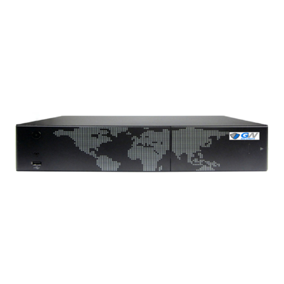
Page 5: Product Appearance
2. Product Appearance (GW2208E-P shown) 3. Device Installation 3.1 NVR Connections Diagram Follow the pictures below when connecting cables and components. (GW2208E-P shown) Official Website: w ww.gwsecurityusa.com Email: s upport@gwsecurityusa.com Business Hours: Mon-Fri 9am to 5:30pm PST/PDT Tel: 626-350-0555... -
Page 6: Installing A Hdd
(GW3208E shown) 3.2 Installing a HDD Open the front panel as pictured. Install the HDD into the HDD placement bracket. Step 1: Open the HDD bracket by unlatching the metal clip on back of the bracket. Place the bracket around the HDD and ensure the SATA port connectors are aligned with the opening in the bracket and not covered. -
Page 7: Basic Operation
4. Basic Operation 4.1 Powering On and Shutting Down the NVR To power on the NVR, flip the power switch located on the rear of the unit after connecting the power cable, monitor, mouse, and installing the HDD. (GW2208E-P shown) To shut down the NVR, press the Shutdown button on the front of the unit, or by right clicking and selecting [Shutdown] from the menu in the NVR interface. -
Page 8: Mouse Operation
4.3 Mouse Operation The NVR interface is operated by a mouse after connecting one to the unit’s USB port. Mouse Part Action Command In Preview: Select current screen and display context menu. Single Click In Menu: Select/Confirm In Preview or Playback: Switch between single and multi-screen display. Double Click In Data Inquiry or Backup: Play a selected segment of video. -
Page 9: The Main Menu
Left click for quick access to the alarm status interface. Left click for quick access to network diagnosis and repair. Left click to adjust the live view screen. & Left click to adjust the channel layout. Left click to show or hide the Navigation Bar. Left click for playback of the last five minutes. -
Page 10: Main Menu Flowchart
5.1 Main Menu Flowchart Flowchart Part 1: Flowchart Part 2: Flowchart Part 3: (Note: Different models may have slightly different menu options. This chart is from the 22XX series.) Official Website: w ww.gwsecurityusa.com Email: s upport@gwsecurityusa.com Business Hours: Mon-Fri 9am to 5:30pm PST/PDT Tel: 626-350-0555... -
Page 11: Data Inquiry
5.2 Data Inquiry Go to [Main Menu] → [Data Inquiry] 5.2.1 Time Inquiry In the [Data Inquiry] interface, left click on the Time Inquiry tab. By moving the mouse cursor onto any point of a channel timeline that has data you can preview a recording of that particular time. Note: 2224E &... - Page 12 Left click Intel Play, choose a channel, and confirm. Left click and drag to select a zone for playback and then left click the icon. Official Website: w ww.gwsecurityusa.com Email: s upport@gwsecurityusa.com Business Hours: Mon-Fri 9am to 5:30pm PST/PDT Tel: 626-350-0555...
-
Page 13: Data Manager
The NVR will now playback all movement detected in the selected zone of that channel. 5.2.2 Data Manager In the [Data Inquiry] interface, left click on the Data Mgr tab. In the Data Manager interface you can check video files based on channel number or video type. -
Page 14: Backup
To initiate playback and manage channel data follow these steps: ● Select a desired channel. ● Select the video type of the channel on the drop down menu. ● Double left click the file segment to start playback. ● Left click on the next/last page icons to view additional pages. ●... -
Page 15: Schedule Backup
5.3.2 Schedule Backup In the Backup interface, left click on Schedule Backup to enter the scheduling interface. To schedule automatic backups, select the channel(s) to be backed up. Set the record mode, the day and time to initiate backup, the destination device, the overwrite parameters, and the file type. Finally, left click save. 5.4 Record Go to [Main Menu] →... - Page 16 The following parameters must be set: ● Channel number: Select a channel from the drop down menu. ● Stream: Select the bit stream type; mainstream or sub-stream. ● Resolution: The resolution range is determined by the connected IP camera. Not all model cameras will have the same resolution options.
-
Page 17: Manual Recording
5.4.2 Manual Recording Go to [Main Menu] → [Record] → [Manual] to enter the manual recording interface. To enable manual recording select the channel(s) you wish to record (recording channels are displayed in blue and channels not recording/selected are displayed in gray), then left click Save. Once the manual recording feature is activated, it will keep recording until turned off. -
Page 18: Alarm Settings
5.5 Alarm Settings Go to [Main Menu] → [Alarm] 5.5.1 Motion Detection Go to [Main Menu] → [Alarm] → [Motion] to enter the motion detection interface. To enable motion detection for a channel follow these steps: ● Before setting up motion detection for a channel, that channel must have it’s recording parameters already input. ●... -
Page 19: Alarm Output
5.5.2 Alarm Output Go to [Main Menu] → [Alarm] → [Alarm Output] to enter the alarm output interface. The following parameters determine how the NVR alarm behaves: ● Alarm Duration: Set the duration an alarm will sound or buzz. The default is 30 seconds. ●... -
Page 20: Ipc Management
Use this feature to enable alarm types other than motion for channels. Select the alarm type and channel and left click Enable Alarm. Multiple alarm types can be selected for the same channel. An email can be linked to the alarm as per motion detection alarms. Copy can be used to copy alarm settings from one channel to another. -
Page 21: Adding Via Manual Add
5.6.1.1 Adding via Manual Add Left click Manual Add to enter the manual addition interface. To manually add a camera follow these steps: ● IP CH: Select the channel number to assign to the camera. ● Dev Type: Device type should automatically default and not be selectable under normal conditions. ●... -
Page 22: Settings Management
● Refresh: Left click Refresh to refresh the list of available cameras. ● Page Flip: If there are multiple pages of cameras, left click the & icons to navigate to other pages. ● Status: The status of a paired camera is displayed. Red indicates abnormal operation, Orange indicates abnormal operation but video is still displaying, Green indicates normal operation. -
Page 23: Time Settings
● Open adaptive optimal resolution: If selected the system will choose the best display resolution base on the monitor connected. ● Display Power on Wizard: If selected the Start-up Wizard will run whenever the system is turned on. ● Saving and enable beep: Select to turn on or off the system beep sound. ●... -
Page 24: Ntp Settings (Internet Time)
DST can be enabled by either week or specific date. In either case, select the times and dates that correspond to when DST begins and ends for your location. 5.7.2.2 NTP Settings (Internet Time) This feature requires the NVR to have internet access to function. The following NTP parameters can be set or changed: ●... -
Page 25: Display Sequence
The following channel parameters can be set or changed: ● Channel No.: Select the channel that will be edited. ● Channel Name: Input a name for the channel. ● Video Mask: Select to enable or disable this feature. If enabled, up to four areas can be selected not to be displayed in the channel video, recording, or both. -
Page 26: Output Mode
5.7.3.3 Output Mode Go to [Main Menu] → [Settings Management] → [Output] → [Output Mode] to enter the output mode interface. This interface allows the output video to be set in one of five preset modes that adjust brightness, color, and sharpness. 5.7.4 Network Sub-menu Go to [Main Menu] →... -
Page 27: Network Settings
5.7.4.1 Network Settings Go to [Main Menu] → [Settings Management] → [Network] → [Network] to enter the network settings interface. This interface allows for the manual modification of network addresses and ports. In most cases these parameters should be left as is unless a complex NVR system is being set up. It is highly recommended that only a professional network technician or other qualified technician alter these parameters. -
Page 28: Pppoe Settings
For ORAY, Meibu, FreeDNS, no-ip, Dyndns domain names: Sign up for a domain name on the service’s official website, enter the correct required information in the NVR, and left click Save. Set up the username and password you registered on any of those sites, save the setting, and then the system will be able to update the domain name. -
Page 29: Email Settings
5.7.4.4 Email Settings Go to [Main Menu] → [Settings Management] → [Network] → [Email Setting] to enter the email settings interface. In order to send and receive alerts and notifications via email, email parameters must be entered into the system. The following email parameters can be set or changed: ●... -
Page 30: Cloud Service
5.7.4.6 Cloud Service Go to [Main Menu] → [Settings Management] → [Network] → [Cloud Service] to enter the cloud service interface. To enable cloud service follow these steps: ● Select Enable ivview and left click Save. The status displayed should will change from offline to online. ●... -
Page 31: Hdd Manager
A network bridge is a computer networking device that creates a single aggregate network from multiple communication networks or network segments. There are two different network segments on the NVR models with built-in POE switches or SDA ports. The network bridge will bind the network segments together, allowing users to access cameras directly from a computer on the network. -
Page 32: Hdd Group
5.8.2 HDD Group The HDD Group tab allows channels to be recorded to specific storage devices. The channels recording to individual storage devices can be set by left clicking the corresponding Edit button and selecting which channels to record. 5.8.3 Storage Settings The Storage Setting tab allows data overwrite parameters to be set for the system. -
Page 33: Smart
● Channel No.: Select a channel to set its data overwrite parameters. ● Enable: Select to turn on and off the data overwrite parameters for the selected channel. ● Record/Photo Saving Days: Set the number of days recorded data will be stored. Data after the set number of days will be overwritten. -
Page 34: Channel Status
5.9.2 Channel Status This interface displays the current status of all channels and the following information: IP address, protocol, bitrate, and resolution. 5.9.3 Alarm Status This interface displays the alarm information for each channel, including motion detection alarms (yellow), and video lost alarms (blue). -
Page 35: Upgrade
5.10.4 Upgrade Go to [Main Menu] → [System Maintenance] → [Upgrade] to enter the upgrade interface. This interface allows the firmware of the NVR to be updated via FTP or USB device. Alternatively, the NVR firmware can be updated via a remotely connected computer. After updating the firmware, the NVR will automatically restart, and the administrator password will reset to the default. -
Page 36: Nvr Remote Access
6. NVR Remote Access The NVR is capable of remote access via a LAN (local area network) or WAN (wide area network). DirectX 9.0 or higher, Internet Explorer version 6.0 or newer, and Adobe Flash Player is required. Disable or uninstall any browser add-ons if the web interface is not behaving as it should. -
Page 37: Specifications
7. Specifications Model GW-NVR3208E/NVR2208E-8P GW-NVR3216E/NVR3216E-16P GW-NVR3232E-8S 8 Ch. 16 ch. 32 Ch. IP video input Up to 12 MP for the first 2 Ch., up to 8MP for the rest Video/Audio input IP audio input 8 Ch. 16 Ch. 32 Ch. - Page 38 Max. Power 120W 240W Power supply 12V 40W Operating Temperature: -10°C to 55°C (14°F to 131°F) General conditions Humidity: 10 to 90% Dimensions 340 x 217.6 x 77mm (13.8" x 8.5" x 3") (WxLxH) Official Website: w ww.gwsecurityusa.com Email: s upport@gwsecurityusa.com Business Hours: Mon-Fri 9am to 5:30pm PST/PDT Tel: 626-350-0555...
Need help?
Do you have a question about the GW-NVR3208E and is the answer not in the manual?
Questions and answers