
Subscribe to Our Youtube Channel
Related Manuals for Linea Research 88C Series

Summary of Contents for Linea Research 88C Series
-
Page 1: User Guide
44C/88C Series Amplifier LNR series processors Linea Research 44C/88C Series Advanced System Amplifier User Guide Version 1 (For firmware version 1.218 and above) -
Page 2: Table Of Contents
FOR CUSTOMERS IN THE USA ..........................9 FOR CUSTOMERS IN THE CANADA ........................10 Thanks and Unpacking ............................11 Unpacking the Linea Research 44/88 C Series Amplifier ................. 11 INSTALLATION INSTRUCTIONS ..........................12 Mechanical Installation ........................... 12 AC Power Connection ............................13 Introduction and Key Features .......................... - Page 3 Delay ................................25 High Pass Filter ............................25 Parametric Equalisation ..........................26 FIR Shelving EQ ............................26 Parametric Filters ............................26 Routing................................. 26 Output ................................26 Gain and Polarity ............................26 Delay ................................26 High and Low pass Filters ..........................26 LIR Crossover Filtering ..........................
-
Page 4: Important Safety Instructions
Processing Latencies ............................ 33 Overlay Flush ..............................34 Protection Systems ............................34 Summary of Protection Indication ........................34 Incident Reporting ............................35 Performance Logging ............................35 Tipi Third Party Interface ..........................36 Processing Block Diagram ............................ 37 EQ and Filter Response Graphs ........................... 38 Technical Specifications ............................ -
Page 5: Consignes De Sécurité Importantes
Do not install near any heat sources such as radiators, heat registers, stoves or other apparatus (including amplifiers) that produce heat. Do not defeat the safety purpose of the polarized or grounding type plug. A polarized plug has two blades with one wider than the other. A grounding type plug had two blades and a third grounding prong. - Page 6 9. Ne supprimez pas le dispositif de sécurité de la fiche polarisée ou mise à la terre. Une fiche polarisée possède deux lames dont l'une est plus large que l'autre. Une prise de terre a eu deux lames et une troisième broche de terre. La lame large ou la troisième broche sont fournies pour votre sécurité.
- Page 7 AVERTISSEMENT DE SECURITE Ne retirez pas les couvercles, ne desserrez pas les fixations et ne laissez aucune pièce s'introduire dans les ouvertures. AVERTISSEMENT DE SECURITE Le radiateur arrière de cet appareil devient chaud. Evitez tout contact direct avec la peau pendant le fonctionnement et au moins 5 minutes après la mise hors tension de l'appareil.
-
Page 8: Compliance
COMPLIANCE FOR CUSTOMERS IN EUROPE This product complies with both the LVD (electrical safety) 73/23/EEC and EMC (electromagnetic compatibility) 89/336/EEC directives issues by the commission of the European community. Compliance with these directives implies conformity with the following European standards: EN60065 Product safety EN55103-1... -
Page 9: For Customers In The Usa
DECLARATION OF CONFORMITY WITH FCC RULES We, Linea Research Ltd. of 1 Marquis Business Centre, Royston Road, Baldock, Hertfordshire, SG7 6XL, England, declare under our sole responsibility that this family of devices, complies with Part 15 of the FCC Rules. -
Page 10: For Customers In The Canada
FOR CUSTOMERS IN THE CANADA This product complies with CA /CSA C22.2 No.60065-03 Ce produit est conforme avec CA /CSA C22.2 No.60065-03 THIS PRODUCT MUST BE EARTHED. Use only a flexible cable or cord with a green or green / yellow core which must be connected to the protective earthing terminal of a suitable mains plug or the earthing terminal of the installation. -
Page 11: Thanks And Unpacking
All Linea Research products are carefully engineered for world-class performance and reliability. If you would like further information about this or any other Linea Research product, please contact us. We look forward to helping you in the near future. -
Page 12: Installation Instructions
INSTALLATION INSTRUCTIONS Mechanical Installation The 44/88 C Series Amplifier system is designed to be mounted in a standard 19” rack enclosure. Where the amplifier is used in a fixed installation, as long as the bottom unit is supported and there are no gaps between units, it is acceptable to use only the front panel 19”... -
Page 13: Ac Power Connection
To prevent damage to the front panel it is recommended that plastic cups or washers are fitted underneath the rack mounting bolt heads. It is possible to mount multiple 44/88 C Series amplifiers without ventilation gaps between them but it is essential that an unobstructed flow of clean air is available from the front of the unit to the rear. -
Page 14: Introduction And Key Features
Introduction and Key Features Introduction The Linea Research 44/88 C Series Advanced System Amplifier represents current state-of-the-art technology in several areas. This product is the result of several years of research, from which many advances in switched mode power technologies and ever finer detail in signal processing have stemmed. Taking advantage of the latest advances in analogue to digital conversion technologies, the unit achieves performance levels among the very best that engineering permits. - Page 15 Drive Modules The 44/88 C Series processor has a new way of ordering and grouping channels in order to give a more speaker-based approach to controlling, designing and recalling speaker configurations; these are called Drive Modules. A Drive Module is the Processing provided by one Input DSP Block, and a number of Output DSP Blocks, which are associated with one-another by means of routing.
- Page 16 parts of a speaker cluster, such as to add 'Throw' EQ boost so that parts of cluster which are throwing further can have HF absorption correction added. If this EQ is not linear phase, then the zones where the speakers combine may suffer frequency response anomalies.
-
Page 17: Audio Connections
Audio Connections Input Connections For each input channel there are 3 pins of a Phoenix connector for analogue inputs. There is also a 6 pin Phoenix connector for one stream (two channels) of AES3 digital audio. The three terminals marked ‘In’ should be used as the AES3 input to the device. The ‘Link’ terminals are intended to feed a buffered version of the input on to another device. -
Page 18: Amplifier Output Connections
Amplifier Output Connections The 44C amplifier is fitted with one Speakon connector per amplifier channel. The appropriate conductor terminations are shown below and on the rear panel of the unit. Amplifier output connections – 44C Speaker - Speaker + Additionally, the channel 2 output is duplicated on the Speakon connector for amplifier channel 1 for Bi- Amp wiring. -
Page 19: Load Matching
Load Matching Each output of the device can be optimised to drive either a low impedance load (e.g. 2, 4 or 8 Ohms), or a Constant Voltage (C.V.) using the Load parameter in the Output menu. There are several C.V. settings (25V, 70V and 100V Line) which determine the maximum RMS voltage that the amplifier will produce. -
Page 20: Panel Layouts
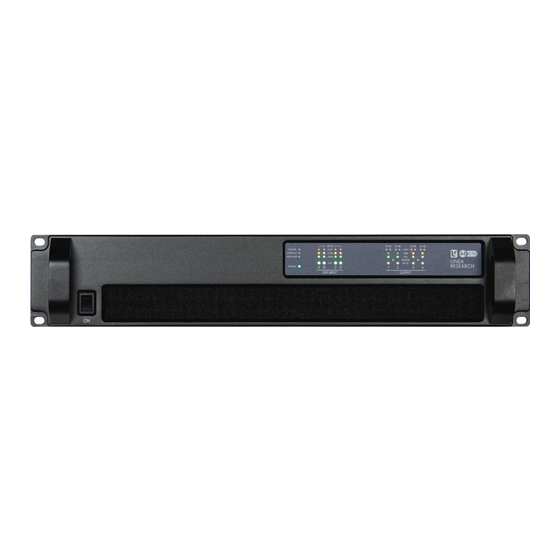
Panel Layouts (The 44C is illustrated. The 88C is similar, but with more input and output indicators) Power Switch- Applies mains power to the device. If the device has entered Sleep mode, it may be woken up again either from the PodWare application, or by switching this switch off, then on again. Status Indicators- The “OVERLAY”... - Page 21 Relay A output: This isolated relay output may be used to indicate abnormal conditions to external monitoring apparatus. The default operation is to indicate a Fault Incident. See Fault Relay Power Inlet: The unit should be connected to a suitable mains electricity supply using an earthed Powercon connection power lead.
-
Page 22: Operation
Operation Starting up the unit When power switch is switched on the unit will go through its start-up cycle, checking all the sub-systems as it does so. Along the way, the indicators will inform you of its progress by lighting more indicators while the indicated progress ‘wheel’... -
Page 23: Drive Module Presets
These concepts are depicted in the PodWare application as in the following example of a 2-way Module: A Snapshot is a device-wide representation of most of the settings in the device. This is represented as four Input Component numbers, eight Output Component numbers, plus a number of machine-centric settings such as routing and Input/Output Analogue/Digital selection etc. -
Page 24: Storing Module Presets
parameters is dependent on the Factory Preset, typically crossover frequencies, output delay and some EQs are hidden; those settings that are a function of the loudspeaker cabinet design and should not require adjustment for different applications. Factory Presets are locked (as indicated by a ‘box’ symbol after the Preset name) so they cannot be over-written. -
Page 25: Automatic Input Selection (Fallover)
As for the AES3 inputs, it is possible to change the gain of the Dante input (when Dante is selected) by adjusting the trim parameter in the Tools>inputs view of the PodWare panel. The amplifier will automatically select the correct sample rate from the incoming stream. For other details on the operation of the Digital Audio Network, please refer to the relevant manufacturer’s documentation. -
Page 26: Parametric Equalisation
Parametric Equalisation There are nine stages of equalisation available for each input channel, three shelving filters and six parametric filters. Equalisation is accessed by clicking the EQ navigation button in the PodWare panel. The presence of an active Group Overlay EQ is indicated by an olive coloured EQ curve being shown. This shows the total combined EQ of all layers. -
Page 27: Lir Crossover Filtering
The 44/88 C Series includes three limiters in the output signal path, accessed by clicking the xover button in the PodWare panel. Please note that whilst the Limiters in this product offer protection for amplifiers and drivers, they can never protect from all possible scenarios, therefore Linea Research is not responsible for any damage which might occur. - Page 28 The Overshoot limiter prevents the signal from exceeding threshold during the attack phase of the main limiter by more than a predetermined amount. The optimal Overshoot setting is usually about 8dB. Lower Overshoot settings will sound progressively ‘harder’. When VX mode is engaged, the user can choose the crossover point of a ‘virtual crossover’, which incorporates two limiters per output so the user can individually limit the drivers in a passive 2-way enclosure using individual thresholds, and optimised attack and release characteristics for each.
-
Page 29: Bridge
Note: For further information on setting up limiters, please see the Application Note DE3457 Setting Up Limiters. Bridge When an amplifier pair is set to Bridge Mode, it uses two amplifier channels to drive one loudspeaker with greater power. In this mode, only one set of Output controls is active per pair of amplifier channels since both of the amplifiers in the pair are driven with the same signals, as determined by the left-hand (lower numbered) channel of the pair controls. -
Page 30: Store Snapshot
WARNING – Do NOT use Static mode unless your IT system specifically requires it. Auto mode should always be used where possible since in this mode, the Device can always be ‘discovered’ by the PodWare application. When in Static mode, the IP Address will flash on the Home screen. If you cannot communicate with the device and the IP address of the device is in an unknown state, you can restore it to Auto mode by pressing and holding the recessed button on the rear of the device for about 10 seconds. -
Page 31: Dhcp
When first installing and launching PodWare, the computer Firewall may ask to allow PodWare to access the network. NOTE: This must be allowed for both private and public networks. DHCP There are two primary IP address ranges – one used when there is a DHCP server, and another (‘Link Local’) where there is no DHCP server (so the Device and the Computer will instead use 'Auto IP' to allocate themselves an IP address). -
Page 32: Aux Port A
Also see Aux Port Tipi Third Party Interface The parameters inside the Drive Modules are not individually stored in Snapshots. Recalling a Snapshot will merely trigger the recall of the appropriate Input and Output Components, rather than restoring the parameters that were active when the Snapshot was stored. This has the distinct advantage that the library of OEM presets may be updated without having to be concerned about what parameters might have been saved in users Snapshots. -
Page 33: Rs232/ Rs485
5v, Gnd: This power output may be used for energising external indicators etc from either the Fault relay or Check relay for example. This output is not capable of supplying more than 100mA of current. Hb: The Heartbeat output. This outputs a 1Hz square wave all the time the unit is operating correctly. RS232/ RS485 Serial communications Connectors: The device may be controlled via this ‘third party interface’... -
Page 34: Overlay Flush
LIR Linear Phase crossover (500Hz) 2.38ms VxLim Lim (VX mode on, 1KHz Fsplit) 0.358ms Total 3.525ms Note that the latencies within a Drive Module are equalised among outputs of that Drive Module. That is, padding delay will be automatically added to some outputs such that the total latency is the same in each output of a Drive Module. -
Page 35: Incident Reporting
Thermal limiting Will show on all output channels Incident Reporting In the PodWare application, a coloured indicator appears on a Device Bar in the System View which displays the Incident state of the device. The Incident state may be one of three states: ... -
Page 36: Tipi Third Party Interface
Tipi Third Party Interface Whilst the device can be set up and controlled entirely using a dedicated control panel in the PodWare PC application, Tipi provides a powerful yet very simple means of controlling the device using ASCII strings from a very wide range of controller devices. -
Page 37: Processing Block Diagram
Processing Block Diagram... -
Page 38: Eq And Filter Response Graphs
EQ and Filter Response Graphs... -
Page 42: Technical Specifications
Max ambient temperature (full power, no limiting) 40degC (105degF) Audio Amplifier topology Proprietary 5th generation Linea Research Class D. Amplifier modulation scheme Low feedback, multiple loop, with feedforward error correction. Dynamic range (analog input to speaker output) >113dBA typ. -
Page 43: Power Output
Power Output Model 44 series C20 44 series C10 44 series C06 RMS output power per channel, all channels driven with continuous program material Power specification and a nominal ambient temperature of 40degC / 105degF Crest Factor of 4 (12dB), 2-Ohm nominal load 5,000W 2,500W 1,500W... -
Page 44: System Protection
System protection Speaker protection Excessive output current Audio soft-clip limiter Excessive power supply current VxLim, Multiband peak limiter (Unique to Linea) Excessive amplifier section temperature VxMax, Multiband overshoot limiter (Unique to Linea) Excessive power supply section temperature Vx-Xmax, Driver excursion limiter Excessive DSP section temperature Vx-Tmax, Driver thermal limiter (long term power limiter) -
Page 45: Options
Options There is internal provision for digital audio network option cards to be factory fitted. Currently Linea Research support Dante from Audinate. Rear rack support kit (part number ZA1182).
Need help?
Do you have a question about the 88C Series and is the answer not in the manual?
Questions and answers