Advertisement
Quick Links
selec
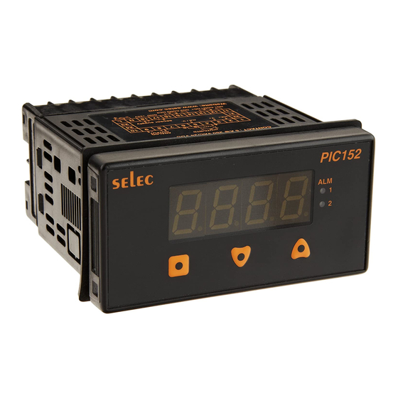
PIC152N
Operating Instructions
48 x 96
SPECIFICATIONS
DISPLAY
4-digit (7 segment LED) 0.5" height Display Messages:
"Or" - a) Appears when measurement exceeds
display scaling range(9999) for signal inputs
b) When open sensor is detected. (Applicable
for TC/RTD/-5 to 56mV)
"rE"
a) Appears when measurement is below
display scaling range (-1999) for signal inputs.
B) Sensor reverse condition occurs.
(Applicable for TC/RTD/mV)
Display alternating between PV and ALrM with LED of
respective alarm flashing.
(Programmable annunciator
option)
LED Status Annunciators - Alarm ON (2 nos)
POWER
85 to 270V AC/DC (AC : 50 or 60Hz),
5VA (Optional) - 24V DC
SETTINGS
Via three keys on front panel.
MEMORY
Nonvolatile EEPROM retains all programmable
parameters and values.
MAIN SENSOR INPUT
(Universal)
Thermocouple inputs
o
J
: -200 to 750 C
o
K
: -200 to 1350 C
o
T
: -200 to 400 C
o
R
: 0 to 1750 C
o
S
: 0 to 1750 C
RTD input (2 wire or 3 wire)
o
PT100 : -100 to 850 C
Signal inputs
mV (linear) : - 5 to 56mV
Voltage
: 0 - 10V DC
Current
: 0 - 20mA DC
INDICATION ACCURACY
±
o
Temperature : 0.25% of Span 1 C (20min.Warmup)
±
Signal input : 0.05% 1 digit
ALARM OUTPUTS
2 nos : Relay output : 5A @ 250V AC or 24V DC
Alarm modes - Alarm High, Alarm Low, Band, Fault
output and Fault diagnosis.
Hysteresis - Programmable.
Annunciator - Programmable.
Reset Action - Programmable : automatic or latched.
Standby Mode - Programmable : enable or disable.
SENSOR SUPPLY
24V DC supply to power the sensor
LINEAR DC OUTPUT
(optional)
Re-transmission : 4 to 20mA or 0 to 5V or 0 to 10V
Update rate : 100msec.
ENVIRONMENTAL CONDITIONS
o
o
Operating Range :
0 C to 50 C
o
o
Storage Range
: -20 C to 75 C
Humidity
: 85% max.
ISOLATION BREAKDOWN RATINGS
AC line with respect to all inputs and outputs : 2000
Volts. All other inputs and outputs with respect to
relay contacts : 2000V AC
CONNECTION
Wire clamping screw terminals
WEIGHT
300 grams
SAFETY PRECAUTIONS
All safety related codifications ; symbols and instructions
that appear in this operating manual or on the equipment
must be strictly followed to ensure the safety of the operating
personnel as well as the instrument.
If the equipment is not handled in a manner specified
by the manufacturer it might impair the protection provided
by the equipment.
CAUTION :
Read complete instructions prior to
installation and operation of the unit.
CAUTION :
Risk of electric shock.
WIRING GUIDELINES
CAUTION :
1. To prevent the risk of electric shock power supply to
the
equipment must be kept OFF while doing the wiring
arrangement.
2. Wiring shall be done strictly according to the terminal
layout with shortest connections. Confirm that all
connections are correct.
3. Use lugged terminals to meet M3 screws.
4. To eliminate electromagnetic interference use of short
wire with adequate ratings and twists of the same in
equal size shall be made.
5. Cable used for connection to power source, must have
2
a cross section of 1mm or greater. These wires shall
have insulation capacity made of at least 1.5KV.
MAINTENANCE
1. The equipment should be cleaned regularly to avoid
blockage of ventilating parts.
2. Clean the equipment with a clean soft cloth. Do not
use Isopropyl alcohol or any other cleaning agent.
INSTALLATION GUIDELINES
CAUTION :
1. This equipment, being built-in-type, normally becomes
a part of main control panel and in such case the
terminals do not remain accessible to the end user
after installation and internal wiring.
2. Conductors must not come in contact with the internal
circuitry of the equipment or else it may lead to a
safety hazard that may in turn endanger life or cause
electrical shock to the operator.
3. Circuit breaker or mains switch must be installed
between power source and supply terminals to
facilitate power 'ON' or 'OFF' function. However this
switch or breaker must be installed in a convenient
position normally accessible to the operator.
CAUTION :
1. The equipment shall not be installed in environmental
conditions other than those mentioned in this manual.
2. Fuse Protection : The equipment does not have a built
in-type fuse. Installation of external fuse of rating 275V
AC/1Amp for electrical circuitry is highly recommended.
3. Thermal dissipation of equipment is met through
ventilation holes provided on chassis of equipment.
Such ventilation holes shall not be obstructed else it
can lead to a safety hazard.
4. The output terminals shall be strictly loaded to the
manufacturer specified values/range.
MECHANICAL INSTALLATION
For installing the controller
1. Prepare the panel cutout with proper dimensions as
shown
OUTLINE
PANEL CUTOUT
Dimensions (in mm)
Dimensions
(in mm)
50
45
46
97.5
92
88
10
2. Remove clamp from the controller and push the
controller into the panel cutout. Secure the controller in
its place by pushing the clamp on rear side.
3. For proper sealing, tighten the screws evenly with
required torque.
CAUTION:
The equipment in its installed state must not come in
close proximity to any heating sources, caustic vapors,
oils, steam, or other unwanted process by-products.
EMC Guidelines:
1. Use proper input power cables with shortest connections
and twisted type.
2. Layout of connecting cables shall be away from any
Internal EMI source.
TERMINAL CONNECTIONS
mV/TC/RTD
+
-
ANALOG
OUTPUT
A
mA+ V+
mA / V-
sensor supply
GND +24V
-
+
NO1
COM1 NC1
NO2 COM2
NC2
TERMINAL DESCRIPTION
TERMINAL
Live
L
Neutral
N
+ve mA
2
+ve V
3
+ve mV / TC / RTD1
4
- ve mV / TC- / RTD 2 / -ve mA / - ve V
5
+ve analog output
8
-ve analog output
9
NO for relay1
11
COM for relay1
12
NC for relay1
13
NO for relay2
14
COM for relay2
15
NC for relay2
16
GND / -ve sensor supply
17
+24 V / +ve sensor supply
18
FRONT PANEL DESCRIPTION
selec
PIC152
ALM
1
2
Key press
Functions
+
together for 3 seconds
To enter or exit program mode
or
till Level is displayed.
To change levels
+
/
to increase or
decrease the level number.
To view function on the
or
key once to view
same level and to display
next / previous function.
the current option.
+
To increase or decrease the
to increase and
+
value of a particular function.
to decrease the
value of particular function.
NOTE : The unit will autoexit program mode after
60
seconds
of inactivity.
To enter or exit program mode :
Press
&
together for 3 seconds
KEY PRESS
DISPLAY
DESCRIPTION
Lock code
Press
+
Enter valid lock code as set
for 3sec
in the
parameter of
level 0.
NOTE :
Lock code will not be prompted if jumper
(besides the calibration jumper) is present.
s e l e c
Insert
Jumper J1
P I C 1
5 2
R 1
R 2
PROGRAMMING OF LEVELS
PROGRAMMING OF LEVEL 0
KEY PRESS
DISPLAY
DESCRIPTION
Press
Parameters in this level
Press
+
can be set.
Press
key to select input sensor type
Default setting : J
for 1sec Input sensor
Display
selection
o
J ( -200 to 750 C )
o
K (-200 to 1350 C)
Press
+
o
Press
+
T (-200 to 400 C)
o
R (0 to 1750 C)
Press
+
o
S (0 to 1750 C)
Press
+
o
Press
+
PT100 ( -100 to 850 C)
Press
+
mV (linear) -5 to 56mV
Press
+
10V DC
Press
+
20mA DC
J1
Advertisement

Related Manuals for Selec PIC152N

Summary of Contents for Selec PIC152N
- Page 1 3. Thermal dissipation of equipment is met through FRONT PANEL DESCRIPTION ENVIRONMENTAL CONDITIONS PIC152N ventilation holes provided on chassis of equipment. Operating Range : 0 C to 50 C Operating Instructions Such ventilation holes shall not be obstructed else it...
- Page 2 KEY PRESS DISPLAY DESCRIPTION NOTE : After altering the value of the input parameters FUNCTIONS MENU press for change to actually take effect. Press key to select Input value scaling point 2 Default value : 20.0mA NOTE : NOTE : This parameter is not prompted if TC/RTD input types Programming steps for Level1 ( Alarm1...
- Page 3 KEY PRESS DISPLAY DESCRIPTION NOTE : Applicable only if Analog output is available. USER GUIDE USER GUIDE limits of the input range. (Factory settings example will display 0.0 at 0mA input and display 9999 at 20.00mA Press key to select Alarm mode. PROGRAMMING OF LEVEL 3 ALARM MODES input.) Reverse acting indication can be accomplished by...
- Page 4 CHECKED BY : Eg : To give 0-20mA DC analog input Two-wire Transmitter (Specifications subject to change as development is a continuous process.) Selec Controls Pvt. Ltd., India Factory Address : mA+ V+ mA / V- EL-27/1, Electronic Zone, TTC Industrial Area, GND +24V MIDC, Mahape, Navi Mumbai - 400 710, INDIA.
Need help?
Do you have a question about the PIC152N and is the answer not in the manual?
Questions and answers