Table of Contents
Advertisement
INSTALLATION INSTRUCTION
MODEL: P4UCB30N12206 - 122 MBH OUTPUT
FOR YOUR SAFETY
WHAT TO DO IF YOU SMELL GAS
•
Do not try to light any appliance.
•
Open windows.
•
Do not touch any electrical switch;
do not use any phone in your building.
•
Extinguish any open flame.
•
Immediately call your gas supplier from a
neighbor's phone. Follow the gas supplier's
instructions.
•
If you cannot reach your gas supplier, call the
fire department.
®
UPFLOW GAS-FIRED FURNACE
Supersedes: 650.64-N3Y (992)
INDUCED-DRAFT
CAUTION
THIS PRODUCT MUST BE INSTALLED IN STRICT COM-
PLIANCE WITH THE ENCLOSED INSTALLATION IN-
STRUCTIONS AND ANY APPLICABLE LOCAL, STATE, AND
NATIONAL CODES INCLUDING BUT NOT LIMITED TO,
B U I L D I N G , E L E C T R I C A L A N D M E C H A N I C A L
CODES.
WARNING
IMPROPER INSTALLATION MAY CREATE A CONDITION
WHERE THE OPERATION OF THE PRODUCT COULD
CAUSE PERSONAL INJURY OR PROPERTY DAMAGE.
FOR YOUR SAFETY
Do not store or use gasoline or other flammable
vapors and liquids in the vicinity of this or any
other appliance
.
WARNING: Improper installation, adjustment, al-
teration, service or maintenance can cause injury
or property damage. Refer to this manual. For as-
sistance or additional information, consult a quali-
fied installer, service agency or the gas supplier.
650.64-N4Y (195)
035-11008
Advertisement
Table of Contents

Related Manuals for York P4UCB30N12206


Summary of Contents for York P4UCB30N12206
- Page 1 INDUCED-DRAFT INSTALLATION INSTRUCTION Supersedes: 650.64-N3Y (992) 650.64-N4Y (195) 035-11008 MODEL: P4UCB30N12206 - 122 MBH OUTPUT CAUTION THIS PRODUCT MUST BE INSTALLED IN STRICT COM- PLIANCE WITH THE ENCLOSED INSTALLATION IN- STRUCTIONS AND ANY APPLICABLE LOCAL, STATE, AND NATIONAL CODES INCLUDING BUT NOT LIMITED TO, B U I L D I N G , E L E C T R I C A L A N D M E C H A N I C A L CODES.
-
Page 2: Table Of Contents
650.64-N4 A separate request for inspection by the carrier’s agent should be TABLE OF CONTENTS made in writing. Also, before installation, the unit should be checked for screws or bolts which may have loosened in transit. GENERAL INFORMATION Description ..............2 NOTES, CAUTIONS &... -
Page 3: Clearances
650.64-N4 In the U.S. only, furnace shall not be connected to a chimney NOMENCLATURE flue serving a separate appliance designed to burn solid fuel. P 4 UC B30 N 122 06 A Check the rating plate and power supply to be sure that Style electrical characteristics match. -
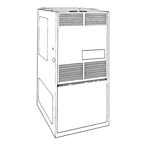
Page 4: Dimensions
650.64-N4 All dimensions are in inches and are approximate. Model P4UCB30N12206 32-1/4 30-3/4 31-1/2 49-3/4 13-5/32 An adapter is supplied and must be field installed FIGURE 1 - FURNACE DIMENSIONS TABLE 2 - RATINGS & PHYSICAL/ELECTRICAL DATA Max. Blower Total Max. -
Page 5: Venting
650.64-N4 The size of combustion air openings previously discussed will VENT SAFETY CHECK PROCEDURE not necessarily govern when a special engineering design WARNING: If this furnace is replacing a common- ensures an adequate supply of air for combustion and ventilation. vented furnace, it may be necessary to resize the Where the return duct system is not complete, the return existing vent line and chimney to prevent oversizing... -
Page 6: Filters (Upflow/Horizontal)
650.64-N4 When the furnace is used in conjunction with a cooling coil, the furnace must be installed parallel with, or on the upstream side of the cooling unit to avoid condensation in the primary heat exchanger. When a parallel flow arrangement is used, the dampers or other means used to control air flow must be adequate to prevent chilled air from entering the furnace, and if manually operated, must be equipped with means to prevent operating of either... -
Page 7: Gas Piping
650.64-N4 ELECTRICAL POWER CONNECTION Field wiring to the unit must conform to and be grounded in accordance with the provisions of the National Electrical Code ANSI/NFPA No. 70 -latest edition, Canadian Electric Code C22.1 Part 1 - (latest edition) and/or local codes. Electrical wires which are field installed shall conform with the tempera- ture limitation for 63°F/35°C rise wire when installed in accord- ance with instructions. -
Page 8: Safety Conrols
650.64-N4 Set the heat anticipator in the room thermostat to 1.16 amps. TABLE 2 - GAS RATE (Cubic Feet Per Hour) Setting it higher will cause the room thermostat to exceed the setpoint. Seconds for Size of Test Dial One Revolution NOTE: Some electronic thermostats do not have 1/2 cubic foot 1 cubic foot... -
Page 9: Adjustment Of Manifold Gas Pressure
650.64-N4 NOTE: To find the Btuh input, multiply the number of WARNING: If manifold pressure is too high, an over- fire condition exists which could cause heat ex- cubic feet of gas consumed per hour by the BTU changer failure. If the manifold pressure is too low, content of the gas in your particular locality. -
Page 10: Adjustment Of Fan Off Settings
650.64-N4 1. Remove the belt and loosen the set screw in the adjustable limit switch should reclose and the main burners relight after flange of the motor pulley. the proper re-start period. 2. Close the pulley to decrease the temperature rise; open OPERATION AND MAINTENANCE the pulley to increase the rise. -
Page 11: Maintenance
650.64-N4 If flame is established for more than 10 seconds after ignition, 3. Remove the upper access door. the controller will clear the ignition attempt (re-try) counter. If 4. Disconnect wires from HSI sensor, rollout switch and HSI flame is lost after 10 seconds, it will restart the ignition se- igniter. -
Page 12: Sequence Of Operation
650.64-N4 CAUTION: Label all wires prior to disconnection Start the system by setting the thermostat above room tem- when servicing controls. Wiring errors can cause perature. Observe the system’s response. Then use the Trou- improper and dangerous operation. bleshooting Table on page 16 to check the system’s operation. Use the table by reading the upper left-hand box and then The following visual checks should be made before trou- following the instructions in each box. -
Page 13: Unit Wiring Diagram
650.64-N4 WIRING DIAGRAM Unitary Products Group... -
Page 14: Blower Performance
0.30 0.40 0.50 0.60 0.70 0.80 0.90 1.00 1.10 1.20 Closed 3382 3277 3084 2925 2760 2625 2465 P4UCB30N12206 1 Open 3740 3623 3477 3356 3227 3032 2869 2659 2347 2232 2096 High Static Drive 3 Open 3573 3396 3237... -
Page 15: Troubleshooting Chart
650.64-N4 WHITE-RODGERS 50E47 SYSTEM TROUBLESHOOTING TABLE Unitary Products Group... - Page 16 Unitary Products Group P.O. Box 1592, York, Pennsylvania USA 17405-1592 Subject to change without notice. Printed in U.S.A Code: SBY Copyright © by York International Corporation 1995. All Rights Reserved. 650.64-N4Y (195)
Need help?
Do you have a question about the P4UCB30N12206 and is the answer not in the manual?
Questions and answers