
Related Manuals for Aerotech BL 20-40

Summary of Contents for Aerotech BL 20-40
- Page 1 Hardware Manual (Revision 2.02.00) Dedicated to the Science of Motion Aerotech, Inc. 101 Zeta Drive, Pittsburgh, PA, 15238 Phone: 412-963-7470 Fax: 412-963-7459 www.aerotech.com...
- Page 2 1/7/03 This product is intended for light industrial manufacturing or laboratory use. Product names mentioned herein are used for identification purposes only and may be trademarks of their respective companies. Copyright © 2003 - 2010 Aerotech, Inc. All rights reserved.
-
Page 3: Table Of Contents
3.6. Single Brush Motor 3.7. Multiple Brush Motor (requires -TP Option) 3.8. Cables Chapter 4: Maintenance 4.1. Control Board Assembly 4.1.1. Fuse Replacement 4.2. Preventative Maintenance Appendix A: Warranty and Field Service Appendix B: Current Changes Index Reader's Comments www.aerotech.com... - Page 4 Table of Contents www.aerotech.com...
-
Page 5: List Of Figures
Velocity Command Configuration Figure 3-3: Torque (Current) Command Configuration Figure 3-4: Dual-Phase Command Configuration Figure 3-5: Differential Dual-Phase Command Configuration Figure 3-6: Single Brush Motor Configuration with Tachometer Figure 3-7: Multiple Brush Motor Configuration Figure 4-1: BL Control Board Assembly www.aerotech.com... - Page 6 List Of Figures www.aerotech.com...
-
Page 7: List Of Tables
Table 4-3: Control Board Jumper Selections Table 4-4: Control Board Test Points Table 4-5: BL Fuse Replacement Part Numbers Table 4-6: Line Voltage Fuse Information Table 4-7: Preventative Maintenance Table B-1: Revision 2.02.00 Manual Changes Table B-2: Recent Manual Changes www.aerotech.com... - Page 8 List of Tables viii www.aerotech.com...
-
Page 9: Ec Declaration Of Conformity
Declaration of Conformity EC Declaration of Conformity Manufacturer Aerotech, Inc. Address 101 Zeta Drive Pittsburgh, PA 15238 Product Model/Types This is to certify that the aforementioned product is in accordance with the applicable requirements of the fol- lowing Directive(s): 2006/95/EC... - Page 10 Declaration of Conformity www.aerotech.com...
-
Page 11: Chapter 1: Introduction
Fault, cur- rent, and velocity outputs simplify monitoring drive status. In addition, there is an option to drive three brush motors in torque mode. Figure 1-1: BL Linear Amplifier Connection Overview www.aerotech.com Chapter 1... -
Page 12: Table 1-1: Amplifier Options
= C for 100 VAC single phase input power x = D for 200 VAC single phase input power Options -VM1 Brushless motor, electronic Tachometer, 0° commutation offset (Aerotech standard ) -VM2 Brushless motor, electronic Tachometer, 30° commutation offset -VM3... -
Page 13: Electrical Specifications
Introduction 1.1. Electrical Specifications The electrical specifications for the BL are listed below. Table 1-2: Electrical Specifications Description BL 20-40 BL 10-40 BL 10-80 Motor Supply Input Voltage 100, 115, 200, 230 VAC (model dependent) Input Frequency 50-60 Hz Inrush Current 10, 11.5, 20, 23 A (model dependent) -
Page 14: Mechanical Design
Each unit should be separated from other drives and surrounded by 50 mm (2") of free air space. A space of 100 mm (4") should be allowed along the front of the unit for cable connections. Figure 1-3: Dimensions Table 1-3: Physical Specifications Model Weight 8.5 kg [18.8 lb] Chapter 1 www.aerotech.com... -
Page 15: Environmental Specifications
Maximum relative humidity is 80% for temperatures up to 31°C. Decreas- ing linearly to 50% relative humidity at 40°C. Non condensing. Altitude Up to 2000 meters. Pollution Pollution degree 2 (normally only non-conductive pollution). Indoor use only. www.aerotech.com Chapter 1... - Page 16 Introduction Chapter 1 www.aerotech.com...
-
Page 17: Chapter 2: Installation And Configuration
N O T E : Aerotech brushless motors should be configured for 0° Hall commutation shift. Motors from other manufacturers may require a 30° Hall commutation offset. Consult the motor manufacturer for details. -
Page 18: Safety Procedures And Warnings
Operators should be trained before operating this equipment. N O T E : The BL (all Aerotech equipment) is not to be used in a manner not specified by Aerotech, Inc. To minimize the possibility of bodily injury and electrical shock, make certain that electrical power is disconnected (Mains disconnect) from amplifier before performing system maintenance or wiring. -
Page 19: Power Connections
2.00 mm (#14 AWG) Protective Ground (Required for Safety) 2.00 mm (#14 AWG) Table 2-2: Control Supply Terminal Block Mating Connector Type Aerotech P/N Phoenix P/N Wire Size: AWG [mm 3-Pin Terminal Block ECK00213 1754465 12-30 [3.3 - 0.0516] www.aerotech.com Chapter 2... -
Page 20: Motor Supply Connections
Motor Bus Input Connections Table 2-3: Motor Supply Input Wiring Description Wire Size 2.0 mm 2 (#14 AWG) 115/100/208/230 Volt AC Input 2.0 mm 2 (#14 AWG) 115/100/208/230 Volt AC Input 2.0 mm 2 (#14 AWG) Protective Ground (Required for Safety) Chapter 2 www.aerotech.com... -
Page 21: Motor Output Connections (Tb101)
2.0 mm (#14 AWG) Earth Ground to Motor (required for safety) 2.0 mm (#14 AWG) Table 2-5: Control Supply Terminal Block Mating Connector Type Aerotech P/N Phoenix P/N Wire Size: AWG [mm 5-Pin Terminal Block ECK00212 1754504 12-30 [3.3 - 0.0516] www.aerotech.com... -
Page 22: Dip Switch
Switches 5 through 8 determine the level where the continuous output current will produce a fault. This type of protection is known as an electronic fuse. Failure to set these switches can result in damage to the amplifier. Chapter 2 www.aerotech.com... - Page 23 Example: Setting Continuous Current Limits (BL20) To set the continuous current limit to 5.5A: 5.5A Continuous RMS x 1.414 = 7.8A continuous peak (7.8A continuous peak/20A max peak) x 100 = 39%. Open switches 1 and 4; close switches 2 and 3. www.aerotech.com Chapter 2...
-
Page 24: Potentiometers (Pots)
This figure illustrates a portion of the pre-amplifier circuit that is accessible to the user for adjusting com- mand signal gains. Figure 2-3: Command Signal Adjustment of the Pre-Amplifier Circuit Chapter 2 www.aerotech.com... -
Page 25: Control Interface Connector (J101)
(amplifier enabled or faulted). -ILMT CCW directional current limit input. Input -ICMD Current command monitor. Rep- Output resentative of the current command (self commutating modes only). 1. Denotes input pull up to internal +5 VDC through a 10K resistor www.aerotech.com Chapter 2... -
Page 26: Encoder Inputs (J101)
Installation and Configuration 2.6.1. Encoder Inputs (J101) The Encoder input signals provide encoder position information to the amplifier. The encoder inputs can also be used to derive an electronic tachometer signal Figure 2-4: Encoder Inputs Chapter 2 www.aerotech.com... -
Page 27: Hall-Effect Inputs (J101)
The Hall-effect input signals provide motor rotor position information to the amplifier. Hall-effect input signals are recommended for AC brushless motor commutation but not absolutely required. The Hall-effect inputs accept 5-24 VDC level signals. Figure 2-5: Hall-Effect Inputs www.aerotech.com Chapter 2... -
Page 28: Input
(Pin 21 of J101). A positive voltage on J101-21 causes CW motor rotation (torque or velocity mode). For single ended com- mand operation, ground this connection and connect signal to Pin 8 of J101. Figure 2-6: ±Input Chapter 2 www.aerotech.com... -
Page 29: Limit Inputs (J101)
Installation and Configuration 2.6.4. Limit Inputs (J101) When pulled to its active state, motion is inhibited (jumper selectable). Figure 2-7: Limit Inputs www.aerotech.com Chapter 2... -
Page 30: Current Command Inputs (J101)
A and B currents. Figure 2-8: Current Command Inputs N O T E : Refer to Section 3.2. Velocity Command Configuration and Section 3.3. Torque Command Con- figuration (Current) for Six Step Phase ICMD. Chapter 2 www.aerotech.com... -
Page 31: Tach Input (J101)
This allows the amplifier to close the servo loop and control the stability of the loop. If an encoder is used for velocity feedback, this pin serves as an output for monitoring velocity (approx. 1V/KRPM). Figure 2-9: Tach Input www.aerotech.com Chapter 2... -
Page 32: Shutdown Input (J101)
Installation and Configuration 2.6.7. Shutdown Input (J101) Jumper selectable active high or active low input. It is used to shut off power stage and therefore remove all power to the motor. Figure 2-10: Shutdown Input Chapter 2 www.aerotech.com... -
Page 33: Fault Output (J101)
Jumper selectable active high or active low (open collector) output.It is used to indicate the status of the power stage (amplifier enabled or faulted). The output device (Q22) can sink up to 160 mA of current. Figure 2-11: Fault Output www.aerotech.com Chapter 2... -
Page 34: Motor And Feedback Phasing
1 indicates five volts or logic high. N O T E : If an Aerotech brushless motor is used with the BL amplifier, motor phase and HALL connections can be determined by referring to the system interconnection drawings in Figure 3-2, Figure 3-3, and Figure 3-4. - Page 35 1. Aerotech phasing configuration expects ØC to be the lead signal (in time), ØB to follow it, and ØA to follow ØB. This means that whichever signal has its sine wave peak farthest to the left should be designated as the ØC signal.
- Page 36 After the motor leads have been tested, the next step is to determine the phase of the Hall signals. The required (by an Aerotech system) relationship between motor and Hall leads is that the peak of a motor lead signal should correspond to the low voltage phase of the Hall signal (the relationship is shown in Figure 2- 13).
- Page 37 With the designations of the motor and Hall leads of a third party motor determined, the motor can now be connected to an Aerotech system. Connect motor lead A to motor connector A, motor lead B to motor con- nector B, and motor lead C to motor connector C. Connect Hall lead A to Pin 4 of the feedback connector.
- Page 38 Installation and Configuration Chapter 2 www.aerotech.com...
-
Page 39: Chapter 3: Wiring Configurations
Wiring Configurations Chapter 3: Wiring Configurations BL drives can be wired into a system in one of two modes (brush or brushless). For a list of motor and feed- back cables, refer to Section 3.8. Cables. www.aerotech.com Chapter 3... -
Page 40: Three-Phase Brushless Motors With Unconnected Phases
The BL Series amplifier overcomes this problem by providing the RT (return) connection for six wire motors, like the Aerotech BLM Series linear motors. Since the BL Series amplifier independently controls current in each of its three phases, six wire motors can be connected as shown in Figure 3-1. -
Page 41: Velocity Command Configuration
2). From this signal, the amplifier adjusts the velocity of the motor accordingly depending upon the velocity command from the external controller. In this configuration, the amplifier closes and controls the velocity loop. This configuration can drive both brush and brushless DC motors. Figure 3-2: Velocity Command Configuration www.aerotech.com Chapter 3... -
Page 42: Table 3-1: Velocity Command Mode Bl Configuration
If the TEST switch is closed, the effects of the BAL pot will be magnified. This is useful when applying a test bias signal (for velocity or torque modes) to the amplifier with- out introducing an external command signal. Chapter 3 www.aerotech.com... -
Page 43: Torque Command Configuration (Current)
In this configuration, the output current to the motor is proportional to the current command input. The advan- tage to this configuration is that the sine and cosine signals to the amplifier and a tachometer are not required. This configuration will drive both brush and brushless DC motors. Figure 3-3: Torque (Current) Command Configuration www.aerotech.com Chapter 3... -
Page 44: Table 3-2: Torque Command Mode (Current) Bl Configuration
With this configuration, an input signal of ±10 volts to pins +INPUT and INPUT will produce the maximum current output signal (viewed at J101 pin 25 ICMD) of ±6 volts. DIP switch positions 1 through 4 are used to scale this ±6 volt signal from zero to maximum current. Chapter 3 www.aerotech.com... -
Page 45: Dual-Phase Command Configuration
1-2 OUT, 3-4 IN, 5-6 OUT, 7-8 OUT Dual phase mode 1. Refer to Section 4.1. Control Board Assembly for jumper locations 2. Default Refer to Table 3-1 for complete Velocity Mode settings and Table 3-2 for complete Torque Mode settings. www.aerotech.com Chapter 3... -
Page 46: Differential Dual-Phase Command Configuration
1-2 Out, 3-4 Out, 5-6 Out, 7-8 IN Differential Dual phase mode Refer to Section 4.1. Control Board Assembly for jumper locations Refer to Table 3-1 for complete Velocity Mode settings and Table 3-2 for complete Torque Mode settings. Chapter 3 www.aerotech.com... -
Page 47: Single Brush Motor
Single Brush Motor Mode BL Configuration Jumpers Setting Description 1-2 Out, 2-3 IN Brush mode Refer to Section 4.1. Control Board Assembly for jumper locations Refer to Table 3-1 for complete Velocity Mode settings and Table 3-2 for complete Torque Mode settings. www.aerotech.com Chapter 3... -
Page 48: Multiple Brush Motor (Requires -Tp Option)
Brush mode 1-2 out, 2-3 in TP Mode JP16 1-2 in, 2-3 out TP Mode 1. Refer to Section 4.1. Control Board Assembly for jumper locations 2. Default Refer to Table 3-2 for complete Torque Mode settings. Chapter 3 www.aerotech.com... -
Page 49: Cables
Wiring Configurations 3.8. Cables N O T E : For a complete list of cables, a wiring/assembly drawing, or to identify a cable, see an Aerotech Documentation-CD or your software CD ROM. Table 3-7: Motor Cables for Linear Stages Standard... - Page 50 C19363 C19364 C19851 MaskAlign C21151 PRO115 BMS60 C19363 C19364 C21031 BM75 C19360 C21032 PRO165 BMS100 C19363 C19364 C21031 (1) These cables can be configured for length, backshell, and cable exit direction (45° or 90°, left or right). Chapter 3 www.aerotech.com...
-
Page 51: Table 3-8: Motor Cables For Combination Stages
VascuLathe ASR Linear C19360 C19851 ASR Rotary C19360 C19851 ACS Linear C19360 C19851 ACS Rotary C19363 C19364 C19851 (1) These cables can be configured for length, backshell, and cable exit direction (45° or 90°, left or right). www.aerotech.com Chapter 3... -
Page 52: Table 3-9: Motor Cables For Rotary Stages
BMS60 w/o limits C19363 C19364 C19851 BMS60 with limits C19363 C19364 C19851 AOM360 ARA125 C19363 C19364 C19851 ARA1000 C19363 C19364 C19851 ARMS C19363 C19364 C19851 ART50 Stepper C20251 Brushless C18982 C18983 C18984 ART100 Stepper C20251 Brushless C18982 C18983 C18984 Chapter 3 www.aerotech.com... - Page 53 C19363 C19364 C19851 AVSI100 BMS60 C19363 C19364 C19851 WaferMax T C19363 C19364 C19851 WaferMax Z C19363 C19364 C19851 (1) These cables can be configured for length, backshell, and cable exit direction (45° or 90°, left or right). www.aerotech.com Chapter 3...
- Page 54 Wiring Configurations Chapter 3 www.aerotech.com...
-
Page 55: Chapter 4: Maintenance
Turns green when power is applied. * If the power light flashes continuously and the unit does not operate, there is too much current draw from the 5V power supply or the control supply voltage level is low. www.aerotech.com Chapter 4... -
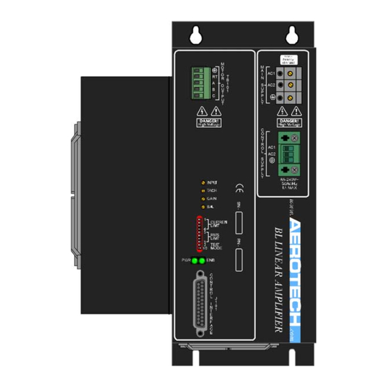
Page 56: Control Board Assembly
Table 4-3 lists the jumpers and the default configurations for the amplifiers. Figure 4-1 highlights where the jumpers are located on the board. Figure 4-1: BL Control Board Assembly Always disconnect the Mains power connection before opening the BL chassis. Chapter 4 www.aerotech.com... -
Page 57: Table 4-3: Control Board Jumper Selections
Square Wave Logic Hall-Effect Inputs (Hall A) JP18 1-2 out, 2-3 in Analog Hall-Effect Inputs (Hall A) 1-2 IN, 2-3 OUT* Square Wave Logic Hall-Effect Inputs (Hall B) JP19 1-2 out, 2-3 in Analog Hall-Effect Inputs (Hall B) * Default www.aerotech.com Chapter 4... -
Page 58: Table 4-4: Control Board Test Points
Maintenance Table 4-4: Control Board Test Points Test Point Description Common +12V -12V Analog Hall A Analog Hall B TP10 Current Command B TP11 Current Command A TP12 Current Command C Chapter 4 www.aerotech.com... -
Page 59: Fuse Replacement
Maintenance 4.1.1. Fuse Replacement Table 4-5 lists the manufacturer and Aerotech’s part number for typical replacement fuses. Additional fuse information can be found on the system drawing supplied with the unit. Always disconnect the Mains power connection before opening the BL chassis. -
Page 60: Preventative Maintenance
BL while cleaning. Do not allow cleaning substances or other fluids to enter the BL or to get on to any of the connectors. Avoid cleaning labels to prevent removing the label information. Chapter 4 www.aerotech.com... -
Page 61: Appendix A: Warranty And Field Service
Aerotech makes no warranty that its products are fit for the use or purpose to which they may be put by the buyer, where or not such use or purpose has been disclosed to Aero-... - Page 62 Warranty and Field Service On-site Warranty Repair If an Aerotech product cannot be made functional by telephone assistance or by send- ing and having the customer install replacement parts, and cannot be returned to the Aerotech service center for repair, and if Aerotech determines the problem could be war-...
-
Page 63: Appendix B: Current Changes
Revision History Appendix B: Current Changes Table B-1: Revision 2.02.00 Manual Changes Section Description Chapter 2 Added supported wire gauges for quick connect terminal blocks www.aerotech.com Appendix B... -
Page 64: Table B-2: Recent Manual Changes
Load table removed. Related to Table 2-6 1.08.00 Dip switch equation example added. Section 2.4. DIP Switch Differential Dual Phase Mode: Section 3.5. Differential Dual-Phase Com- mand Configuration 1.07.00 ICMDA pin numbers corrected Jumper settings corrected Appendix B www.aerotech.com... -
Page 65: Index
Control Supply specifications Current Command Inputs (J101) LED Description Limit Inputs Declaration of Conformity Differential Dual-Phase Command Configuration 36 Maintenance dimensions Mechanical Design DIP Switch Minimum Load Dual-Phase Command Configuration Modes of Operation Motor Cables for Combination Stages Electrical Specifications www.aerotech.com... - Page 66 Peak Output Current specifications Pollution Warnings Potentiometers Wiring POTs Control Supply Power Amplifier Bandwidth specifications Motor Supply Power Connections TB102 Preventative Maintenance Wiring Configurations Protective Features relative phasing/order Safety Procedures and Warnings Shutdown Input (J101) Single Brush Motor Tach Input (J101) TB101 www.aerotech.com...
-
Page 67: Reader's Comments
How do you use this document in your job? Does it meet your needs? What improvements, if any, would you like to see? Please be specific or cite examples. Name Title Company Name Address Mail your comments to: Fax to: Aerotech, Inc. 412-967-6870 101 Zeta Drive Email: Pittsburgh, PA service@aerotech.com 15238 U.S.A.
Need help?
Do you have a question about the BL 20-40 and is the answer not in the manual?
Questions and answers