Table of Contents
Advertisement
Quick Links
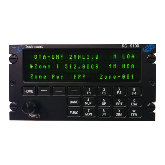
RC-9100
MULTIBAND P25 AIRBORNE REMOTE CONTROL
Installation Instructions
TiL Document No. 14RE508
Rev. B
Issue 1
NOVEMBER 2015
Technisonic Industries Limited
240 Traders Boulevard, Mississauga, Ontario L4Z 1W7
Tel: (905) 890-2113 Fax: (905) 890-5338
www.til.ca
Copyright by Technisonic Industries Limited. All rights reserved.
Advertisement
Table of Contents

Related Manuals for TIL RC-9100

Summary of Contents for TIL RC-9100
-
Page 1: Installation Instructions
RC-9100 MULTIBAND P25 AIRBORNE REMOTE CONTROL Installation Instructions TiL Document No. 14RE508 Rev. B Issue 1 NOVEMBER 2015 Technisonic Industries Limited 240 Traders Boulevard, Mississauga, Ontario L4Z 1W7 Tel: (905) 890-2113 Fax: (905) 890-5338 www.til.ca Copyright by Technisonic Industries Limited. All rights reserved. - Page 3 TECHNISONIC INDUSTRIES LIMITED REVISION HISTORY [ 14RE508 ] For the most current revision of this document, please check the Technisonic website: www.til.ca SECTION EDITED DESCRIPTION DATE - PAGE - Original Document Release. Nov. 25, 2014 H.D. iv & 10 Changes made to DO-160G: Sep.
- Page 4 TECHNISONIC INDUSTRIES LIMITED This page is intentionally left blank. RC-9100 Installation Instructions TiL 14RE508 Rev. B Issue 1...
- Page 5 Changes or modifications not expressly approved by Technisonic Industries could void the user’s authority to operate the equipment. This manual is designed to provide information about the RC-9100. Every effort has been made to make this manual as complete and accurate as possible.
- Page 6 (end users) in support of regulatory agency approval. Please refer to the Technisonic website www.til.ca for the latest issue of available STCs and letter of authorization for use. RC-9100 Installation Instructions...
-
Page 7: Table Of Contents
WARRANTY ........................12 LIST OF FIGURES FIGURE TITLE PAGE Outline Drawing for Model RC-9100 ................. 3 Wiring Connections and Notes for the RC-9100 ............... 5 LIST OF TABLES TABLE TITLE PAGE Wire Connections (9-Pin D-Connections – J1) ..............4 RC-9100 Installation Instructions... - Page 8 TECHNISONIC INDUSTRIES LIMITED This page is intentionally left blank. RC-9100 Installation Instructions TiL 14RE508 Rev. B Issue 1...
-
Page 9: Introduction
This publication provides installation information on the RC-9100 remote control. DESCRIPTION The RC-9100 is designed to be a remote control head for the TDFM-9100 series of airborne transceivers. It is a secondary (slave) control point and is not intended to replace the function of the front panel of the radio. - Page 10 TECHNISONIC INDUSTRIES LIMITED This page is intentionally left blank. RC-9100 Installation Instructions TiL 14RE508 Rev. B Issue 1...
-
Page 11: General
INSTALLATION The RC-9100 Remote Control is designed to be Dzus mounted and should be installed in conjunction with an IN-RC91 installation kit. See Figure 1 for an outline drawing of the unit with dimensions to facilitate the installation. -
Page 12: Pin Locations And Connections
TX Data Auto ON TABLE 1 Wire Connections INSTALLATION - WIRING INSTRUCTIONS Figure 2 shows all required connections and recommended wire sizes for the RC-9100 Remote Control. 2.6.1 MAIN GROUND – PIN 1, J1 Pin 1 should be connected to ground. The pin is internally connected to the chassis. -
Page 13: Wiring Connections And Notes For The Rc-9100
TECHNISONIC INDUSTRIES LIMITED FIGURE 2 Wiring Connections and Notes for the RC-9100 RC-9100 Installation Instructions TiL 14RE508 Rev. B Issue 1... -
Page 14: Post Installation Emi Test
POST INSTALLATION EMI TEST APPENDIX TO INSTALLATION INSTRUCTIONS POST INSTALLATION EMI TEST 2.7.1 PURPOSE The purpose of this test is to identify any interference that the RC-9100 remote control head may cause with existing aircraft systems. 2.7.2 TEST CONDITIONS The RC-9100 should be installed and function tested. The TDFM-9100 transceiver should be on throughout this test. -
Page 15: Procedure
TECHNISONIC INDUSTRIES LIMITED 2.7.5 PROCEDURE List the power plant, fuel, and other electric instruments not already included in the chart below and note any anomalies that occur due to operation of the RC-9100. Assess the results. STEP SYSTEM PASS FAIL NOTES Com 1 &... - Page 16 TECHNISONIC INDUSTRIES LIMITED Fuel % Torque % Enunciators Digital Clock Oil Pressure DME 1 & 2 Autopilot Stability Augmentation Systems Coupled ILS Approach RC-9100 Installation Instructions TiL 14RE508 Rev. B Issue 1...
-
Page 17: Appendix A Support Notes
High Temperature – Short Time Operating 4.5.3 + 70 degrees C High Temperature – Operating 4.5.4 + 70 degrees C In-Flight Loss of Cooling 4.5.5 Not applicable Altitude 4.6.1 50,000 feet RC-9100 Installation Instructions TiL 14RE508 Rev. B Issue 1... - Page 18 Indicated test was performed by ULTRATECH LABS. NOTE-2 Testing included subparagraph 16.6.1.3b: Requirement for Equipment with Digital Circuits. NOTE-3 Only applies to units with Mod 6 marked on the modifications label. RC-9100 Installation Instructions TiL 14RE508 Rev. B Issue 1...
- Page 19 TECHNISONIC INDUSTRIES LIMITED NOTES RC-9100 Installation Instructions TiL 14RE508 Rev. B Issue 1...
-
Page 20: Warranty
Technisonic. This Warranty shall not be transferable or assignable to any other persons, firms, or corporations. For warranty registration, please complete the online Warranty Registration Form found at www.til.ca. RC-9100 Installation Instructions TiL 14RE508 Rev. B Issue 1...
Need help?
Do you have a question about the RC-9100 and is the answer not in the manual?
Questions and answers