Ceragon FibeAir IP-20E Installation Manual
Hide thumbs
Also See for FibeAir IP-20E:
- User manual (945 pages) ,
- User manual (825 pages) ,
- User manual (597 pages)

Related Manuals for Ceragon FibeAir IP-20E


Summary of Contents for Ceragon FibeAir IP-20E
-
Page 1: Installation Guide
FibeAir IP-20E ® Installation Guide Part ID: BM-0293-0 Doc ID: DOC-00042181 Rev A.01 May 2014 Copyright © 2014 by Ceragon Networks Ltd. All rights reserved. - Page 2 Installation Guide Notice This document contains information that is proprietary to Ceragon Networks Ltd. No part of this publication may be reproduced, modified, or distributed without prior written authorization of Ceragon Networks Ltd. This document is provided as is, without warranty of any kind.
-
Page 3: Table Of Contents
Connecting the Ethernet Cable ..................30 3.8.1 Preparing the Ethernet Cable and Plug-in Field ............30 3.8.2 Preparing the Ethernet Cable Already Assembled ............32 3.8.3 Connection of Ethernet Cable to IP-20E ..............33 Ceragon Proprietary and Confidential Page 3 of 52... - Page 4 5. Installation Procedures per Configuration Type .......... 42 1+0 Direct Mount ......................42 1+1 HSB Direct Mount ....................46 2+0 Direct Mount ......................49 6. Appendix A: Mediation Device Losses ............52 Ceragon Proprietary and Confidential Page 4 of 52...
-
Page 5: About This Guide
FibeAir® IP-20E Installation Guide About This Guide This guide describes the FibeAir IP-20E installation procedures and provides additional information concerning system parts and frequency bands. What You Should Know For the warranty to be honored, install the unit in accordance with the instructions in this manual. -
Page 6: Before You Start
To avoid malfunctioning or personnel injuries, equipment or accessories/kits/plug-in unit installation, requires qualified and trained personnel. Changes or modifications not expressly approved by Ceragon Networks could void the user's authority to operate the equipment. Where special cables, shields, adapters and grounding kits are supplied or described in this manual, these items must be used, to comply with the FCC regulations. -
Page 7: Précautions Générales Relatives À L'équipement
électriques. Bruit de machine d’ordre - 3. GPSGV, le plus haut niveau de pression sonore s'élève à 70 dB (A) au maximum, dans le respect de la norme ISO EN 7779. Ceragon Proprietary and Confidential Page 7 of 52... -
Page 8: Allgemeine Vorsichtsmaßnahmen Für Die Anlage
Marking is done according to standard practice unless otherwise specified by customers. The following details should be marked: Customers address Contract No Site name (if known) Case No Ceragon Proprietary and Confidential Page 8 of 52... -
Page 9: Inspection
Check the packing lists and ensure that correct parts numbers quantities of goods have arrived. Inspect for any damage on the cases and equipment. Report any damage or discrepancy to a Ceragon representative, by e-mail or fax. Ceragon Proprietary and Confidential... -
Page 10: Product Hardware Description
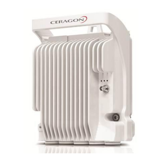
FibeAir® IP-20E Installation Guide Product Hardware Description IP-20E Hardware Overview FibeAir IP-20E features an all-outdoor architecture consisting of a single unit directly mounted on the antenna. IP-20E Rear View (Left) and Front View (Right) Cable Gland Construction Ceragon Proprietary and Confidential... -
Page 11: Ip-20E Interfaces
Data Ports 2 and 3 for GbE traffic (two different assembly options): Electric10/100/1000Base-T RJ-45, or Optical: SFP supporting 1000Base-LX or 1000Base-SX or 1000Base-ZX-XD External DC Connection – Ceragon proprietary DC interface Management Port: 10/100Base-T RJ-45 Antenna Port– Ceragon proprietary flange (flange compliant with UG385/U) ... -
Page 12: Poe Injector
PoE Injector PoE Injector Interfaces Power-Over-Ethernet (PoE) Port GbE Data Port supporting 10/100/1000Base-T DC Power Port 2 ±(18-60)V DC Power Port 1 ±(18-60)V Grounding screw PoE Injector Ports Ceragon Proprietary and Confidential Page 12 of 52... -
Page 13: System Components
The presence of a specific component in this manual does not indicate that it is available for ordering. Please consult with your respective pre-sales engineer for specific component availability. Symmetrical / Asymmetrical Coupler IP-20E (Splitter) PoE Injector Ceragon Proprietary and Confidential Page 13 of 52... -
Page 14: Adaptors And Installation Kits
POE Injector all outdoor, redundant DC input, +24VDC PoE_Inj_AO_2DC_24V_48V support, -48VDC support PoE_Inj_AO PoE Injector all outdoor, -48VDC PoE_Inj_19inch_Rack_Mnt_kit PoE Injector 19” Rack Mount Kit PoE_Inj_ETSI_Rack_Mnt_kit PoE Injector ETSI Rack Mount Kit Ceragon Proprietary and Confidential Page 14 of 52... -
Page 15: Antenna Connection
Temperature range for exceptional temperatures; tested successfully, with limited margins: -45°C (-49°F) to +60°C (140°F) Humidity: 5%RH to 100%RH IEC529 IP66 Storage: ETSI EN 300 019-1-1 Class 1.2 Transportation: ETSI EN 300 019-1-2 Class 2.3 Ceragon Proprietary and Confidential Page 15 of 52... -
Page 16: Cable Installation And Grounding
Whether or not the power source provides constant power (i.e., power is secured on weekends or is shut off frequently and consistently). The power supply must have grounding points on the AC and DC sides. Ceragon Proprietary and Confidential Page 16 of 52... -
Page 17: Available Cable Options
IP-20 Fiber Optic Multi Mode LC2LC Outdoor use 50m IP-20_FO_MM_LC2LC_OUT_75m IP-20 Fiber Optic Multi Mode LC2LC Outdoor use 75m IP-20_FO_MM_LC2LC_OUT_100m IP-20 Fiber Optic Multi Mode LC2LC Outdoor use 100m IP-20_FO_MM_LC2LC_OUT_300m IP-20 Fiber Optic Multi Mode LC2LC Outdoor use 300m Ceragon Proprietary and Confidential Page 17 of 52... -
Page 18: Cables For Protection Data Sharing And Management Connections
Surge Protection Requirements section of the IP-20E Technical Description, provided the Ethernet cables were prepared according to the instructions in Connecting the Ethernet Cable on page 30. Ceragon Proprietary and Confidential Page 18 of 52... -
Page 19: Securing The Cables
DUAL FEEDER CLAMP FOR RG-8/U CABLE 6 WAY. SI-0764-0 RG8 4 feeder clamp DUAL FEEDER CLAMP FOR RG-8/U CABLE 4 WAY. SI-0763-0 RG8 2 feeder clamp DUAL FEEDER CLAMP FOR RG-8/U CABLE 2 WAY. Ceragon Proprietary and Confidential Page 19 of 52... -
Page 20: Special Instructions For Use Of Glands
Installation Guide Special Instructions for use of Glands In order to remove the plastic plugs for the unit, you can use the flange of supplied glands to disconnect them. See below pictures Ceragon Proprietary and Confidential Page 20 of 52... -
Page 21: General Installation Procedure
1 Before inserting a cable. you must disassemble the gland cap and gland rubber from the gland body. 2 Slide the gland cap into the cable. 3 Slide the gland rubber into the cable. 4 Slide the cable into the body of the gland. Ceragon Proprietary and Confidential Page 21 of 52... - Page 22 Important Note! Pay attention that the gland rubber is properly located and not damaged during the tightening of the gland cap. 7 Secure the cable to the gland using a tie wrap. Ceragon Proprietary and Confidential Page 22 of 52...
-
Page 23: Connecting An Optical Fiber Cable And Sfp
3 Remove the gland cap and rubber from the gland body. 4 Slide the gland cap into the cable. 5 Slide the rubber into the cable. 6 Insert wires with connector one by one into the cable gland. Ceragon Proprietary and Confidential Page 23 of 52... - Page 24 FibeAir® IP-20E Installation Guide 5 Connect the wires to the SFP transceiver. Listen for the “click” to ensure that it is fully inserted. 6 Connect the connector into the IP-20E plug connector. Ceragon Proprietary and Confidential Page 24 of 52...
- Page 25 Then, tighten the gland again. If the gland thread is damaged do not use it! Ceragon Proprietary and Confidential Page 25 of 52...
- Page 26 FibeAir® IP-20E Installation Guide Secure the cable to the gland using a tie wrap. Ceragon Proprietary and Confidential Page 26 of 52...
-
Page 27: Connecting A Dc Power Cable
4 Insert the power cable wires into the power connector. 5 Match “+” and “–” to the red and black cord colors according to the power supply connection cord colors. 6 Tighten the two top screws. Ceragon Proprietary and Confidential Page 27 of 52... - Page 28 FibeAir® IP-20E Installation Guide 7 Plug the power cable with connector into the IP-20E power connector. 8 Tighten the two front screws. Ceragon Proprietary and Confidential Page 28 of 52...
- Page 29 Tightening the gland at an angle can ruin the thread on the gland and prevent proper sealing of the interface. 10 Tighten the gland cap. 11 Secure the cable to the gland with a tie wrap. Ceragon Proprietary and Confidential Page 29 of 52...
-
Page 30: Connecting The Ethernet Cable
5 Insert the CAT5E plug boot facing up into the cable. 6 Roll back the foil shield insulation and wrap the drain wire around the foil. Do not remove any insulation from the conductors. Ceragon Proprietary and Confidential Page 30 of 52... - Page 31 13 Push back the CAT5E plug cover on the connector plug. Note: It is recommended that the newly prepared cable be tested with a Cable Analyzer such as the FLUKE DTX-1800 (or the equivalent), to make sure the cable complies with ANSI/TIA/EIA-568-B-2. Ceragon Proprietary and Confidential Page 31 of 52...
-
Page 32: Preparing The Ethernet Cable Already Assembled
1 Release the gland cap and the gland rubber slightly. 2 Insert the CAT5E cable into the gland cap and into the rubber gland. 3 Insert the CAT5E cable into the gland body. Ceragon Proprietary and Confidential Page 32 of 52... -
Page 33: Connection Of Ethernet Cable To Ip-20E
Tightening the gland at an angle can ruin the thread on the gland and prevent proper sealing of the interface. Ceragon Proprietary and Confidential Page 33 of 52... - Page 34 FibeAir® IP-20E Installation Guide 4 Tighten the gland cap. 5 Secure the cable to the gland using a tie wrap. Ceragon Proprietary and Confidential Page 34 of 52...
-
Page 35: Poe Injector Installation And Connection
1 On the right side of each PoE Injector, loosen the screw, plain washer, and serrated washer. 2 Place the cable lug (supplied with the PoE injector kit) between the plain and serrated washer. 3 Tighten the screw. Ceragon Proprietary and Confidential Page 35 of 52... -
Page 36: Poe Injector Wall Mount Installation
2 Drill two 6mm diameter holes with 100mm distance between the center of the holes. 3 Insert the anchors with the bolts. 4 Place the washers on the bolt. 5 Tighten the nuts. Ceragon Proprietary and Confidential Page 36 of 52... -
Page 37: Poe Injector Pole Mount Installation
2 Pass the hose clamp through the pole mount slots. Note! The Hose Clamp is not supplied with PoE injector kit. 3 Attach the PoE injector to the pole. Ceragon Proprietary and Confidential Page 37 of 52... -
Page 38: Poe Injector 19" Rack Installation
1 Mount the PoE Injector to a 19” rack using a 19” rack adaptor. 2 Mount the PoE Injector on the 19” adaptor through the wall mounting holes, using M6 screws and washers. Ceragon Proprietary and Confidential Page 38 of 52... - Page 39 FibeAir® IP-20E Installation Guide 3 Mount the 19” rack adaptor to a 19” rack using four M6 screws and cage nuts. Ceragon Proprietary and Confidential Page 39 of 52...
-
Page 40: Poe Injector Etsi Rack Installation
1 Mount the PoE Injector to an ETSI rack using a 19” rack adaptor and ETSI adapting ears. 2 Connect the ETSI adapting ears to a 19” rack adaptor using four M6 screws. Ceragon Proprietary and Confidential Page 40 of 52... - Page 41 4 Mount the 19” rack adaptor with the ETSI ears on the ETSI rack using four M6 screws and cage nuts. Note: For this type of installation, a 2RU space is required. Ceragon Proprietary and Confidential Page 41 of 52...
-
Page 42: Installation Procedures Per Configuration Type
The following tools are required for the IP-20E installation: Metric offset hexagon key wrench #6 Phillips #2 screwdriver Procedure Note: If necessary, change the antenna polarization to the desired polarization in accordance with the relevant antenna installation guide. Ceragon Proprietary and Confidential Page 42 of 52... - Page 43 FibeAir® IP-20E Installation Guide Horizontal / Vertical Pole Twist Orientation Ceragon Proprietary and Confidential Page 43 of 52...
- Page 44 “V” on the pin as shown below and fasten the two screws. 5 Mount the IP-20E on the antenna using the four M8 captive screws and washers that are supplied, assembled, in the IP-20E, and tighten the screws. Ceragon Proprietary and Confidential Page 44 of 52...
- Page 45 FibeAir® IP-20E Installation Guide Note: Make sure the polarization mounting direction of the IP-20S is correct. Ceragon Proprietary and Confidential Page 45 of 52...
-
Page 46: 1+1 Hsb Direct Mount
1 If necessary, change the coupler polarization to the desired polarization and re-tighten the screws. Important: Make sure the polarization mounting direction of the twist to the coupler is according to the antenna polarization. Ceragon Proprietary and Confidential Page 46 of 52... - Page 47 3 Verify that the two O-Rings supplied with the IP-20E Coupler kit are well assembled on the coupler body. If not, please assemble them and make sure the mounting direction is correct, as shown in the section view. Ceragon Proprietary and Confidential Page 47 of 52...
- Page 48 4 Mount both IP-20E radios to each side of the coupler using the four M8 captive screws and washers that are supplied, assembled, in the IP-20E, and tighten the screws. Make sure the O-rings are well placed before tightening the radios to the coupler. Ceragon Proprietary and Confidential Page 48 of 52...
-
Page 49: 2+0 Direct Mount
Remove the existing rectangular transition, swap the O- ring, and install the circular transition instead. Circular Adaptor 1 Connect the IP-20E OMT to the antenna and secure it with four screws. Verify the existence of the O-ring. Ceragon Proprietary and Confidential Page 49 of 52... - Page 50 V polarization. For horizontal polarization, locate the alignment hole in the twist plate aside the letter “H” on the pin, as shown below, and fasten the two screws. Ceragon Proprietary and Confidential Page 50 of 52...
- Page 51 4 Mount each IP-20E radio to the side of the IP-20E OMT body that matches the polarization of the radio, using the four M8 captive screws and washers supplied and assembled in the IP-20E radio, and tighten the screws. Ceragon Proprietary and Confidential Page 51 of 52...
-
Page 52: Appendix A: Mediation Device Losses
FibeAir® IP-20E Installation Guide Appendix A: Mediation Device Losses Device Type Maximum Insertion Loss (Main/Secondary) 0.5dB (both on V and H) Splitter 1:2 3.7:3.7dB Coupler 1:4 2:7dB Ceragon Proprietary and Confidential Page 52 of 52...
Need help?
Do you have a question about the FibeAir IP-20E and is the answer not in the manual?
Questions and answers