Table of Contents
Advertisement
R
EAD THIS
HERE
C
LICK
Introduction
Congratulations on choosing a ClearPath all-in-one servo system. We know that
when most people get a new tech product, they want to try it out right away. For
that reason ClearPath is ready to go right out of the box. Your ClearPath motor was
shipped to you fully tested and factory preconfigured for unloaded use (i.e. for use
with nothing attached to the shaft). This means you can power it up, connect to your
PC, and start making test moves within minutes. And, when you're ready to connect
ClearPath to a mechanical system, you'll have the world's most advanced Auto-
tuning software to help. Use this Quick Start Guide to get up and running quickly,
but refer to the ClearPath User Manual for complete details on safety, installation,
and operation.
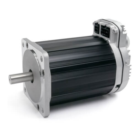
DC Power Connector
(Molex Minifit Jr. 4 pos.)
Sealing
Gasket
NEMA
Mounting
Flange
Parts of a ClearPath
Always use caution and common sense when handling motion control equipment.
Even the smallest ClearPath Motor is powerful enough to remove fingers, turn a tie
into a noose, or tear out a patch of hair and/or scalp in just a few milliseconds (by
comparison, it takes about 100 milliseconds to blink). We're not trying to alarm you
(OK, maybe a little) but we do want all ClearPath users to stay safe
These devices are extremely powerful and dangerous if used carelessly. Please read
and understand all safety warnings in the ClearPath User Manual before operating a
ClearPath Motor.
Teknic, Inc.
C
P
LEAR
ATH
OR
TO CONTINUE ON TO THE
I/O Connector
(Molex Minifit Jr. 8 pos.)
Housing
(Anodized Aluminum)
Stainless
Steel Shaft
Keyway
Read This Warning!
- 1 -
Q
S
G
UICK
TART
UIDE
C
P
U
LEAR
ATH
Communication Port
(USB Micro-B)
Status LED
Die Cast
Heatsink
ClearPath Quick Start Guide rev.2.2
M
SER
ANUAL
Auxilliary PE
(Protective Earth)
Connection Point
and fully intact
.
Advertisement
Table of Contents

Summary of Contents for Teknik ClearPath
- Page 1 For that reason ClearPath is ready to go right out of the box. Your ClearPath motor was shipped to you fully tested and factory preconfigured for unloaded use (i.e. for use with nothing attached to the shaft).
- Page 2 MSP is compatible with Windows 8, 7, XP and Vista. Teknic website: Downloads page Secure your ClearPath to a stable work surface. A “Quick-Grip” style bar clamp or bench vise works well. Tip: You can help preserve your motor’s finish by covering the vise jaws with tape.
- Page 3 Basic power polarity test Start with power supply unplugged. This will prevent electrical arcing from damaging your ClearPath power terminals over time. Always turn off your power supply before connecting or disconnecting the power cable from a ClearPath. If you hear an electrical “snap”...
- Page 4 Plug the power cable into the ClearPath power connector (1). Plug in the power supply (2). The status LED at rear of ClearPath should be on and solid yellow. Teknic IPC-5 ClearPath Motor Power Supply Powering up your ClearPath Connect the USB cable from ClearPath to your PC. For first-time connections, wait for ClearPath to auto-install its drivers before proceeding.
- Page 5 ClearPath mode you’re interested with no additional wiring burden. We used Manual Velocity Mode (available on ClearPath MCPV and MCVC models) for this example. Note: Software control is great for test, development or just learning how ClearPath modes work; however it is not intended for use in a final machine implementation.
- Page 6 The good news is: when you use software controls you don’t need to wire anything to the inputs. You enable the ClearPath and make moves simply by clicking a few controls in the UI. Hardware Indicators Software Controls Manual Velocity Control Mode: Setup Window Enter motion parameters.
- Page 7 Software Controls. Notice that the Enable control box is no longer grayed out, while the Hardware Indicator LEDs now grayed out. Also, the “Soft Knob” control is now green and ready for use. Override Inputs Teknic, Inc. - 7 - ClearPath Quick Start Guide rev.2.2...
- Page 8 Enable the motor by clicking the Enable check box. This immediately energizes the motor coils. When a ClearPath is enabled: The Status changes from Disabled (yellow) to SW Enabled (green). Note: SW Enabled stands for “Software Enabled”. The motor shaft will now actively servo to maintain its present position.
- Page 9 Each click of the “Soft Knob” will cause a speed increase or decrease of 100 RPM. Tip: If you only want ClearPath to spin clockwise, set “Max CCW Velocity” to zero. What to do if you get a shutdown or a warning: If you see a small “warning triangle”...
- Page 10 Be patient. Auto-tune can take up to 30 minutes (more typically 5-15 minutes). • Be calm. Expect to hear humming, buzzing, clicks and clacks. Loud squeals and • buzzes are perfectly normal while ClearPath explores the limits of the system. Teknic, Inc. - 10 - ClearPath Quick Start Guide rev.2.2...
- Page 11 Before you seek technical assistance: The status LED on the back is not lit, and my ClearPath apparently has no power. Plug in and turn on power supply. • Connect power cable to ClearPath. • Check power supply fuse (if any).
- Page 12 ANUAL LEAR OTORS CPM-MC CPM-SD OVERS XX AND 1.97 J 10, 2016 ERSION ( 5 8 5 ) 7 8 4 - 7 4 6 0 ( 5 8 5 ) 7 8 4 - 7 4 5 4 E K N I C O I C E...
- Page 13 HIS PAGE INTENTIONALLY LEFT BLANK...
-
Page 14: Table Of Contents
MSP Scope ............... 31 ClearPath Menu ...............36 : MC F ......41 ODES OF PERATION AMILY Table of ClearPath MC Family Operational Modes ....41 Spin On Power Up ...............42 Mode Summary..............42 How it works ..............42 Mode Controls..............43 Manual Velocity Control..............44 Mode Summary..............44... - Page 15 . 1 . 9 7 L E A R A T H S E R A N U A L How it works ..............44 Mode Controls..............45 Description of Encoder/Knob Settings ......45 Ramp Up/Down To Selected Velocity ......... 47 Mode Summary..............47 How it works ..............
- Page 16 NSTALLATION Mounting Dimensions: ClearPath NEMA 34......92 Mounting Dimensions: ClearPath NEMA 23......93 Mounting Considerations ..........94 Connecting ClearPath to a Mechanical System......94 Motor Connection: General Tips and Guidelines ...94 Notes on Coupling Selection..........96 Installing Pulleys and pinions ......... 97 About End-of-Travel Stops............98 Hard Blocks..............98...
- Page 17 . 1 . 9 7 L E A R A T H S E R A N U A L Internal [Encoder] Resolution ..........106 Positioning Resolution...............106 Input Resolution Setting (in MSP) ..........107 Input Resolution Use Cases........... 107 ..............109 NDEX (585)784-7460 V (585)784-7454 EKNIC...
-
Page 18: Safety Warnings
AFETY ARNINGS IMPORTANT: Read this manual before attempting to install, apply power to, or operate a ClearPath motor. Failure to understand and follow the safety information presented in this document could result in property damage, bodily injury or worse. ERSONAL... -
Page 19: General Disclaimer
A tool shall be required to remove any guards and/or shields. • The ClearPath motor requires a path from its chassis to the Protective Earth (P.E.) connection made to the machine it is installed in. The connection should electrically have the same or larger effective wire gauge or current handling capability as the DC power supplied to the ClearPath Motor. -
Page 20: Introduction
MSP software, connect ClearPath to your PC via USB, and configure and tune your ClearPath. Once setup is complete, disconnect ClearPath from your PC and start moving. With just three inputs and one output, sending commands and receiving feedback is simple and intuitive. -
Page 21: Parts Of A Clearpath Motor
Made in USA. Each ClearPath motor is built and tested in our upstate New York manufacturing facility, so you can be certain you’re getting a high quality, fully tested motion control product right out of the box. -
Page 22: Example Application: Absolute Positioning Mode
ClearPath inputs. In the figure below, a ClearPath model MCPV is coupled to a ball screw positioning stage. For now, we’ll say that ClearPath has already been configured and programmed via the included MSP software. -
Page 23: Overview: Configuring A Clearpath
(using the included MSP software). After homing is complete, ClearPath can be commanded to move to any of the predefined positions by changing the state of Inputs A and B (see table in previous figure: ClearPath Input States vs. -
Page 24: Clearpath I/O: Overview
PLC outputs, microcontroller outputs, and more can be wired to a ClearPath. And, when you change modes, the inputs au tomatically change function to match. ClearP ath motors have no tiny jumpers or DIP switches to deal with. - Page 25 . 1 . 9 7 L E A R A T H S E R A N U A L • Assert at the end of a settled move (based on user-defined settling requ irements). • Output a PW M signal proportional to motor speed. (585)784-7460 V (585)784-7454 EKNIC...
-
Page 26: Getting Started
ClearPath motors can be powered from 24–75VDC power supplies, however the actual minimum voltage and current that will sufficiently power a ClearPath in a given application is highly dependent on the application requirements (i.e. how much torque and speed is required) as well as motor winding and magnet configuration. -
Page 27: Important Note On Lower Voltage Power Supplies
OWER OLTAGE OWER UPPLIES ClearPath motors can and do work successfully when paired with power supplies as low as 24 volts DC, provided that the power supply has sufficient voltage, current, and capacitance to meet your application's motor torque and speed requirements. This assumes that the motor ha been properly sized for the application. -
Page 28: Teknic Power Supplies
Teknic manufactures two 75VDC power supplies designed specifically for powering motor drives—the IPC-3 and IPC-5. These supplies effectively manage peak current demand, regenerated energy, and include several built-in protective features. They are ideal for use with ClearPath motors. Teknic IPC-3 Teknic IPC-5... -
Page 29: Connecting Power To A Clearpath Motor
OWER TO A LEAR OTOR Connect main DC power to the ClearPath power connector, a four positio Molex Minifit Jr. connector. For applications with multiple ClearPath motors, power can be daisy-chained from motor to motor as shown below. The diagram below includes a list of power connector mating parts readily available from most electronic component suppliers. - Page 30 OWER UPPLY ONTROL WITCH The power supply for a ClearPath should not be switched on and off from the DC output side. Switching the DC output side, especially with inexpensive relays, will ultimately result in poor performance (drop outs) due to pitting, corrosion and contact welding. If a power switch is required, install it such that the supply is disconnected from the AC input side (see figure below).
-
Page 31: Connecting I/O To A Clearpath Motor
Limiter 5-24 ClearPath Inputs shown with simple switch and battery inputs 5-24VDC just means ClearPath will work with logic signal sources where logic “low” is 0VDC while logic “high” can be any value between 5VDC and 24VDC inclusive. (585)784-7460 V... - Page 32 Limiter 5-24VDC Enable ClearPath Enable Input Exception: when ClearPath is set to “Spin on Power Up” mode, the motor shaft can move as soon as main DC power is applied, regardless of the state of the Enable Input. (585)784-7460 V...
- Page 33 A T H S E R A N U A L Caution: When ClearPath is in “Spin on Power-Up” mode, it can spin as soon as main DC power is applied. All inputs, including the Enable Input, are ignored in this mode.
- Page 34 A N U A L ONNECTING IGITAL UTPUTS TO LEAR NPUTS ClearPath inputs are compatible with standard digital output formats including open collector transistor, and driven outputs from PLCs, sensors, signal generators, microcontrollers and more. Transistor Outputs ClearPath Input Current...
-
Page 35: Clearpath Output (Hlfb)
HLFB settings can be found on the Advanced drop down menu in ClearPath MSP. This output can be left as a “no connect” if desired. Note: HLFB is not internally powered. This means it works off an external 5–24VDC power source capable of sourcing/sinking at least 1mA non-inductive. - Page 36 ) during periods of acceleration and deceleration. All Systems Go-Torque In ASG-Torque mode, the HLFB output asserts (conducts) when the ClearPath is enabled and the motor shaft is within a tolerance band of the user-specifie d torque. Enable Input Signal...
- Page 37 . 1 . 9 7 L E A R A T H S E R A N U A L HLFB W IRING XAMPLES HLFB Output Wiring Examples 5-24VDC ClearPath Internal (Supply) HLFB Current Limiter PLC Input HLFB - 5-24VDC (Return) 5-24VDC...
-
Page 38: User Software (Clear Path Msp)
Teknic if you have problems with software installation. OMMUNICATING LEAR After ClearPath MSP is installed on your PC, follow the directions below to establish a communication link between your ClearPath and PC. Note: Establishing a ClearPath communication link is required for settin... -
Page 39: First-Time Communication Setup
3. Connect ClearPath to the PC with a USB Type “A” to Micro-B cable. This is a low cost standard cable. 4. Wait! In most cases Windows will detect the connected ClearPath and install the correct USB driver automatically. -
Page 40: Tour Of Clearpath Msp Software
Access Soft Controls. Soft Controls allow you to spin your ClearPath with no hardware inputs connected. With just MSP and a powered up ClearPath, you can enable the motor, turn the inputs on and off, command motion, and monitor the output state. -
Page 41: Dashboard
Caution: Motor is energized with shaft “locked” . ClearPath is in a shutdown state. Motor coils are not energized. ClearPath is connected to a PC but not powered up. (This indicates low or no DC power.) MSP Dashboard Note: The Position Counter is not displayed in velocity or torque modes. -
Page 42: Msp Scope
MSP S COPE VERVIEW The MSP Scope takes real-time streaming data from ClearPath and plots it on the Scope Display to provide a dynamic picture of motor performance. The scope can be used to display your motor’s current torque output, tracking error, commanded velocity, acceleration, and more. - Page 43 MSP Scope The Scope Variable drop down menu lets you select any of 12 ClearPath motion control variables to display. These variables include Tracking Error, Commanded Velocity, Actual Torque, Actual Velocity, Velocity Error, Commanded Torque, SGN (sign of velocity), Measured Position, Commanded Jerk, Commanded Acceleration, Max Phase Voltage, and Torque Error.
- Page 44 . 1 . 9 7 L E A R A T H S E R A N U A L real time. The delta function automatically displays the difference between cursor values. Trace Storage controls allow you to save and display two trac es on the scope display.
- Page 45 . 1 . 9 7 L E A R A T H S E R A N U A L After the single sweep capture, data collection automatically stops • Auto - This is the rolling, “always on” setting. Data is continuously collected, refreshed, and displayed regardless of the trigger source settings.
- Page 46 . 1 . 9 7 L E A R A T H S E R A N U A L TRIP HART The Strip Chart can display a number of additional events and conditions that oc cur in sync with the primary waveform capture. Using the Strip Chart you can view move status (mv), drive events (drv), and I/O states in real time.
-
Page 47: Clearpath Menu
Dashboard section of MSP. Click this menu item to reset RMS Max (this is the maximum RMS value recorded since last reset). ODE MENU Select ClearPath operating modes from this drop down menu. Note: number of available modes varies by model. ETUP MENU Use this menu item to convert velocity and acceleration values from encoder counts to RPM (revolutions per minute). - Page 48 S E R A N U A L DVANCED The Adv anced menu gives you access to several ClearPath global features and settings. Each Advanced Menu item is listed below along with a screenshot of it s dialog window. Torque Foldback...
- Page 49 . 1 . 9 7 L E A R A T H S E R A N U A L Move Done Criteria Move Done status is used to determine when the All Systems Go-Position signal should be asserted at the HLFB output. The Move Done Criteria consist of two parameters: the “In-Range Window”...
- Page 50 . 1 . 9 7 L E A R A T H S E R A N U A L Input A and B Filtering (585)784-7460 V (585)784-7454 EKNIC OICE...
- Page 51 . 1 . 9 7 L E A R A T H S E R A N U A L Disable Behavior This setting determines how ClearPath will decelerate if it is disabled while still in motion. (585)784-7460 V (585)784-7454 EKNIC OICE...
-
Page 52: Modes Of Operation : Mc Family
Bipolar PWM Command Connect a digital waveform (PWM or frequency) from your PLC or other device, and ClearPath will run at a velocity proportional to the w veform. Or, use the Follow Digital Velocity Command PWM output from an H-bridge driver of a brushed motor setup and ClearPath Unipolar PWM Command becomes a high-performance drop-in replacement. -
Page 53: Spin On Power Up
S E R A N U A L OWER UMMARY This is ClearPath’s simplest mode of operation. Just turn on p ower and ClearPath smoothly ramps to your preset velocity. Use this m ode for applications that require reliable constant velocity and a bare minimum of wiring. -
Page 54: Mode Controls
. 1 . 9 7 L E A R A T H S E R A N U A L ONTROLS Enter value (1-100) to limit peak torque capability of motor as a % of motor’ s maximum peak torque. Enter target velocity. -
Page 55: Manual Velocity Control
Turn in one direction to increase CW motor velocity; turn in the other direction to increase CCW velocity. When enabled, ClearPath can either resume running at its last set speed or start at zero speed (and stay at zero speed until commanded to move). -
Page 56: Mode Controls
Light = Input asserted (on) (when using hardware inputs). Dark = Input de-asserted (off) Check to turn on Soft Check to soft enable ClearPath Click arrows to increase or Displays output status Controls. Override cannot (This only works when Soft... - Page 57 “H ” C ETENTS HECKBOX When unchecked, ClearPath treats each quadrature transition it sees as a single “tick”. (Remember, each tick causes an incremental change in motor speed.) When checked, ClearPath treats every 4 quadrature transition it sees at its inputs as one “tick”.
-
Page 58: Ramp Up/Down To Selected Velocity
Velocity 2 Tip: Setting one of the programmable velocities to zero (Velocity 3 in the example Velocity 1 at right) provides a convenient way to stop the motor via the ClearPath inputs. Velocity 3 Velocity 4 Motor velocity vs. time... -
Page 59: Mode Controls
Displays commanded velocity Displays output status. Controls. Override cannot hardware inputs. For use only (when using soft inputs). HLFB modes supported: be activated when ClearPath when Soft Controls are active. >Servo On is hardware enabled. Caution: motor may spin when >AllSystemsGo enabled. -
Page 60: Follow Digital Velocity Command (Bi-Polar Pwm Input)
ODE SUMMARY Connect a digital PWM waveform from your PLC or other device, and ClearPath will run at a velocity proportional to the duty cycle of that waveform. Or, use the PWM output from an H-bridge driver of a brushed motor setup and ClearPath becomes a high-performance drop-in replacement. -
Page 61: Mode Controls
Displays output status Controls. Override cannot Emulate hardware inputs. For Emulates PWM velocity (when using HLFB modes supported: be activated when ClearPath use only when Soft Controls input (for use with Soft Controls). >Servo On is hardware enabled. are active. Caution: motor Soft Controls). - Page 62 • As PWM duty cycle approaches 50%—from either direction—motor velocity approaches 0. • In practice, O% and 100% (static low and static high conditions) are not valid PWM states. ClearPath treats these cases as zero-velocity commands. • PWM minimum on time and minimum off time = 300nS.
-
Page 63: Setting A Pwm Deadband (Optional)
The deadband expands the range about the 50% PWM mark that is n erpreted as the “zero-velocity s etting” by ClearPath. This gives the user a reliable way to ensure that motor velocity ramps to zero when the PW duty cycle is set at (or “close enou gh”... -
Page 64: Follow Digital Velocity Command (Unipolar Pwm Input)
NPUT ODE SUMMA Connect a digital PWM waveform from your PLC or other device, and ClearPath will run at a speed proportional to the duty cycle of the PWM waveform. OW IT WORKS Assert the Enable Input to energize the motor. Once enabled, motor velocity is controlled by sending a PWM signal to Input B. -
Page 65: Mode Controls
Displays output status Controls. Override cannot Emulate hardware inputs. For Emulates PWM velocity (when using HLFB modes supported: be activated when ClearPath use only when Soft Controls input (for use with Soft Controls). >Servo On is hardware enabled. are active. Caution: motor Soft Controls). - Page 66 . 1 . 9 7 L E A R A T H S E R A N U A L • For CW shaft rotation, set Input A high. For CCW shaft rotation, set Input A low. • PWM minimum on time and minimum off time = 300nS (585)784-7460 V (585)784-7454 EKNIC...
-
Page 67: Follow Digital Velocity Command (Frequency Input)
REQUENCY NPUT ODE SUMMARY Connect a digital variable frequency waveform from your PLC or other device, and ClearPath will run at a velocity proportional to the frequency of the waveform. OW IT ORKS Assert the Enable Input to energize the motor. Then, control velocity by applying a variable frequency pulse train to Input B. -
Page 68: Mode Controls
Displays output status Controls. Override cannot Emulate hardware inputs. For Emulates frequency velocity (when using HLFB modes supported: be activated when ClearPath use only when Soft Controls input source (for use Soft Controls). >Servo On is hardware enabled. are active. Caution: motor with Soft Controls). -
Page 69: Follow Digital Torque Command (Bi-Polar Pwm Input)
NPUT UMMARY Connect a digital PWM waveform from your PLC or other device, and ClearPath will produce torque proportional to the duty cycle of the PWM waveform. OW IT WORKS Assert the Enable Input to energize the motor. Control motor torque by applying a PWM signal to Input B. -
Page 70: Mode Controls
Enter maximum speed. Enter value in mS. Determines motor torque (i.e. (optional). See text for ClearPath will shut down if how long ClearPath can spin at full scale torque). description of deadband. this speed limit is exceeded. max speed before shutting down. - Page 71 • As PWM duty cycle approaches 50% from either direction, motor torque approaches 0. • O% and 100% duty cycle (static low and static high conditions) are not valid PWM states. ClearPath interprets these values as zero-torque commands. • PWM minimum on time and minimum off time = 300nS.
-
Page 72: Setting A Pwm Deadband (Optional)
The deadband expands the range about the 50% PWM mark that is n erpreted as the “zero torque setti ng” by ClearPath. This gives the user a reliable way to ensure that motor torque is completely turned off whe n the PWM duty cycle is set at (or “close... -
Page 73: Follow Digital Torque Command (Unipolar Pwm Input)
NPUT ODE SUMMA Connect a digital PWM waveform from your PLC or other device, and ClearPath will run at a speed proportional to the duty cycle of the PWM waveform. OW IT WORKS Assert the Enable Input to energize the motor. Motor torque is controlled be applying a variable PWM signal to Input B. -
Page 74: Mode Controls
See figure be low. • 0% and 100% duty cycle signals (static low and static high respectively) are invalid PWM states, interpreted by ClearPath as “PWM turned off”. This is the equivalent of a zero-torque command. -
Page 75: Follow Digital Torque Command (Frequency Input)
REQUENCY NPUT ODE SUMMARY Connect a digital variable frequency waveform from your PLC or other device, and ClearPath will produce torque that is proportional to the frequency of the waveform. OW IT ORKS Assert the Enable Input to energize the motor. Control torque by applying a variable frequency pulse train to Input B. -
Page 76: Mode Controls
Enter value in mS. Determines motor torque (i.e. full Max Torque setting (25% of peak ); a 1 kHz ClearPath will shut down if how long ClearPath can spin at scale torque). signal will command zero torque. max speed before shutting down. -
Page 77: Move To Absolute Position (2-Position)
OVE TO BSOLUTE OSITION OSITION UMMARY Trigger ClearPath to move to one of two preset locations. This mode was designed for replacing hydraulic or pneumatic cylinders that move between two positions. OW IT ORKS Assert the Enable Input to energize the motor. Once enabled, ClearPath automatically executes a homing move to a [user-supplied] switch or sensor wired to Input B. -
Page 78: Mode Controls
Displays output status Controls. Override Emulate hardware inputs. For HLFB modes supported: cannot be activated use only when Soft Controls >Servo On when ClearPath is are active. Caution: motor >AllSystemsGo hardware enabled. may spin when enabled. >Speed Output OMING ETUP WITCH Homing is required in this mode. - Page 79 . 1 . 9 7 L E A R A T H S E R A N U A L Homing setup dialog 4. Test and modify your homing setup for proper performance. How Switch Homing Works: • During homing, the axis is automatically driven toward the homing switch at the user-specified direction and speed.
-
Page 80: Move To Absolute Position (4-Position)
Enable Logic: High=Enable Low=Disable Trigger Pos 2 Notes: ClearPath must home to a “hard stop” (either upon first enable or upon Pos 1 every enable) to establish a home reference position. All user-defined target Pos 3 positions are referenced to the home position. -
Page 81: Mode Controls
Click during homing Displays output status. Controls. Override cannot hardware inputs. For use only operation to manually HLFB modes supported: be activated when ClearPath when Soft Controls are active. set home position. >Servo On is hardware enabled. Caution: motor may spin when >AllSystemsGo... -
Page 82: Homing (Automatic Hard Stop Homing)
OMING Homing to a hard stop is required in this mode. When homing is initiated, the motor automatically rotates at the user-specified speed, acceleration, and direction until a hard stop is detected. Then ClearPath sets the home position. OMING ETUP Select how often homing is to be performed. -
Page 83: Move To Sensor Position
ClearPath inputs. See illustration below. Assert the Enable Input to energize the motor. Apply User Commands to start motion. ClearPath moves CW or CCW until it interrupts a sensor. It then holds position until you issue a new User Command in the opposing direction. -
Page 84: Mode Controls
In addition, the deceleration rate must be set to ensure that the flag does not travel past the sensor. • Changing the state of either Input A or Input B while ClearPath is in motion effectively cancels the move in progress. C learPath... -
Page 85: Move Incremental Distance (2-Distance)
ISTANCE ISTANCE UMMARY Send a trigger pulse to tell ClearPath to move a user-defined distance from its curren t position. Send multiple, quick trigger pulses to tell ClearPath to ravel a multiple of any distance in one smooth, uninterrupted move. -
Page 86: Mode Controls
Displays output status Controls. Override Emulate hardware inputs. For HLFB modes supported: cannot be activated use only when Soft Controls >Servo On when ClearPath is are active. Caution: motor >AllSystemsGo hardware enabled. may spin when enabled. >Speed Output (585)784-7460 V... -
Page 87: Homing Setup (Home-To-Switch)
2. In MSP, enable homing and click Setup to open the homing setup dialog (shown above). 3. Set When to Home. Choose to perform a homing sequence either 1) the first time ClearPath is enabled or 2) every time ClearPath is enabled. 4. Set Homing Direction. Choose clockwise or counter- clockwise shaft rotation during homing. - Page 88 (in counts) that ClearPath can be commanded to move. Note: ClearPath will not execute a move that would violate this limit. See Advanced Settings, Behavior on L imit Hit, below for additional settings related to this feature.
-
Page 89: Move Incremental Distance (4-Distance)
Send a trigge r pulse to tell ClearPath to move a user-defined distance [increment] from its current position. Send multiple, quick trigger pulses to tell ClearPath to travel a multiple of any distance in one smooth, interrupted move. Incremental Positioning An incremental move is referenced to its own starting position, not to an absolute “home”... -
Page 90: Mode Controls
Click during homing Displays output status. Controls. Override cannot Emulate hardware inputs. For operation to manually HLFB modes supported: be activated when ClearPath use only when Soft Controls set home position. >Servo On is hardware enabled. are active. Caution: motor >AllSystemsGo... -
Page 91: Homing (Automatic Hard Stop Homing)
Homing to a hard stop is optional in this mode. When homing is initiated, the motor automatically rotates at the user-specified speed, acceleration, and direction until a hard stop is detected. Then ClearPath sets the home position. Select how often homing is to be performed. - Page 92 ClearPath will not execute a move that would violate this limit. 6. Set Homing Speed and Homing Accel/Decel. 7. Set Offset Distance. This lets you tell ClearPath exactly how far to move away from the hard stop (in counts) to set the final home position.
-
Page 93: Pulse Burst Positioning
Trigger function: Alternate Speed Briefly pulse the Enable input low, and the next pulse burst sent to ClearPath will result in a move at the alternate speed setting. Once that move is complete, ClearPath automatically returns to its default speed setting. -
Page 94: Mode Controls
Changing this setting does not change the encoders native or comm andable resolution. OMING ETUP OMING n this mode, ClearPath can be configured to home to a hard stop to establish a home reference position before functional positioning begins. (585)784-7460 V (585)784-7454 EKNIC OICE... - Page 95 . 1 . 9 7 L E A R A T H S E R A N U A L Install a hard stop that guarantees the moving element of the axis makes solid, repeatable contact with the stationary element when driven into it. 2.
-
Page 96: Clear Path Sd (Step And Direction )
While all ClearPath SD models function in essentially the same way, there are differences in re solution and power between models within the family. See the Teknic/ClearPath website for complete information on SD Family ClearPaths. TEP AND IRECTION... -
Page 97: Step And Direction Timing
(i.e. an electrical transition from low to high). Refer to the diagram below for details and important step and direction signal timing requirements. ClearPath can be configured to move one count for each step received, or one count per [x steps] received (based on the Input Resolution setting). -
Page 98: Mode Controls
Enter motor acceleration. Controls. Override cannot Emulate hardware inputs. For use with Soft Controls. For use with Soft Controls. be activated when ClearPath use only when Soft Controls is hardware enabled. are active. Caution: motor may spin when enabled. (585)784-7460 V... -
Page 99: Homing Setup (Hard Stop Homing)
OMING ETUP OMING In this mode, ClearPath can be configured to home to a hard stop to establish a home reference position before functional positioning begins. Install a hard stop that guarantees the moving element of the axis makes solid, repeatable contact with the stationary element when driven into it. -
Page 100: Appendix A: Led Blink Codes
A N U A L A: LED B PPENDIX LINK ODES Note: In cases where multiple exceptions use the same blink code, yo must connect ClearPath to a PC running MSP to determine exception type. Exception Affect on Servo How to Clear... - Page 101 . 1 . 9 7 L E A R A T H S E R A N U A L Exception Affect on Servo How to Clear Status or Exception LED Behavior Type Motion Behavior Exception Message Reported in UI Excessive Bus Current Disallows Toggle Enable...
- Page 102 2 C or higher • ClearPath will remain in shutdown state but LED will “wake up” and flash ye llow blink code 6 (see table above for complete description of this exception code). • Toggling the enable...
-
Page 103: Appendix B: Mechanical Installation
. 1 . 9 7 L E A R A T H S E R A N U A L PPENDIX ECHANICAL NSTALLATION NEMA 34 OUNTING ENSIONS LEAR (585)784-7460 V (585)784-7454 EKNIC OICE... -
Page 104: Mounting Dimensions: Clearpath Nema 23
. 1 . 9 7 L E A R A T H S E R A N U A L NEMA 23 OUNTING IMENSIONS LEAR (585)784-7460 V (585)784-7454 EKNIC OICE... -
Page 105: Mounting Considerations
LED are visible and accessible when the motor is mounted to the machine. • Do not mount ClearPath over a heat source such as a power supply, spindle drive, etc. • Do not mount ClearPath in an unventilated enclosure. - Page 106 • Avoid direct loads. In general, ClearPath motors are not designed for connection to direct loads (e.g. direct connection to a grinding wheel). However, direct connection may make sense if the load is of low-mass and balanced, as with small mirrors for laser applications.
-
Page 107: Notes On Coupling Selection
. 1 . 9 7 L E A R A T H S E R A N U A L OTES ON OUPLIN ECTION A complete coverage of the topic Coupling Selection for Servo Applicat ions is beyond the scope of this document, but many articles and esources can be found on the web for those interested in learning more. -
Page 108: Installing Pulleys And Pinions
. 1 . 9 7 L E A R A T H S E R A N U A L Bellows couplings are also excellent for high precision positioning applications. Bellows couplings allo w for more misalignment than jaw couplings but are generally m ore expensive. -
Page 109: About End-Of-Travel Stops
In several modes, ClearPath must home to a hard stop to establish a home reference position before functional positi oning can begin. -
Page 110: Fan Mounting And Cooling
(exceeding the ratings of most other motor drives) your system should always be designed with the best cooling you can reasonably provide. Note: ClearPath will shut down to self-protect when the rear cover temperature reaches 80 degrees C. ClearPath NEMA 34... -
Page 111: Appendix C: Clear Path Cable Pinouts
ClearPath accessory cables available through Teknic and Teknic distribution. CPM-CABLE-CT RL-MU120 Cable description: ClearPath I/O connector cable. Overmolded Molex MiniFit Jr. 8-position connector to standard MiniFit Jr. 8-position connector (no over-mold on one end for easy access to wires). Factory... -
Page 112: Cpm-Cable-Pwr-Mm660
CPM-CABLE-PWR-MS120 Cable description: ClearPath power cable. This cable connects the DC output of a Teknic IPC-3 or IPC-5 power supply to the ClearPath power input connector. It features a Sabre 2-position connector to Molex MiniFit Jr. 4-position connector. -
Page 113: Appendix D: Common Specifications
1 0 2 . 1 . 9 7 L E A R A T H S E R A N U A L D: C PPENDIX OMMON PECIFICATIONS Electrical Power Requirements: Supply Voltage, Typical: 24VDC to 75VDC Supply Voltage, Absolute Min: 21.5VDC (as measured at input terminals) Supply Voltage, Absolute Max: 90VDC (as measured at input terminals) -
Page 114: Appendix E: Grounding And Shielding
AWG nu mber or h avier) as the ClearPath DC power input wiring. Note: In scenarios where ClearPath is not connected to a PE (Protective E th ar ) retur path– such as during bench testing or maintenance–... -
Page 115: Power Returns
Never use the machine frame or chassis as a power return. Use • discrete cable or wires for all power wiring. Use only recommended w ire gauge (16-18AWG typical) for all • ClearPath power wiring. When in doubt, use heavier wire. (585)784-7460 V (585)784-7454 EKNIC OICE... -
Page 116: Appendix F: Part Number Key
E = Positioning Resolution of 6400 counts per revolution; Extended selection of RAS settings. Note: MCVC available in R only. SDHP available in E only. Note: All ClearPath models feature an internal encoder resolution of 12,800 counts per revolution. Motor Shaft Diameter L = Standard shaft diameter Note: Standard diameter is 1/2”... -
Page 117: Appendix G: Encoder Resolution And Input
The number of counts the motor shaft will move for each step sent to the ClearPath Step Input. This is often set at one step per count, but can be adjusted using the Input Resolution setting in MSP (covered later in this section). -
Page 118: Input Resolution Setting (In Msp)
ESOLU TION ASES Note: The examples and screenshots below are based on an 800 count per rev. ClearPath motor. For a 6400 count per rev. mo tor adjust accordingly. • Case #1. You want one step pulse to command one count of rotation (default). - Page 119 #2. You want one step pulse to command m ultiple counts of rotation. ClearPath can be configured such that a single step pulse commands 2, 4, 8, or more counts of moti This is mainly used to compensate for a "slow" controller, i.e controller that can't generate pulses fast enough to command desired peak velocity.
-
Page 120: Index
End-of-Travel Stops, 98 Parts of a ClearPath, 10 Fan Mounting, 99 Power Supply Filter Setting, Input A and B, onnecting power to a ClearPath, 18 I/O (Input/Output) Fusing, 19 ClearPath Output (HLFB), 24 Illustration, 18 Connecting Devices to ClearPath Inputs, 23... - Page 121 1 1 0 . 1 . 9 7 L E A R A T H S E R A N U A L Teknic, Incorporated 115 Victor Heights Pkwy Victor, NY 14564 © 2016 TEKNIC INCORPORATED, ALL RIGHTS RESERVED (585)784-7460 V (585)784-7454 EKNIC OICE...
Need help?
Do you have a question about the ClearPath and is the answer not in the manual?
Questions and answers