Table of Contents
Advertisement
Service Manual
GP3 CHASSIS
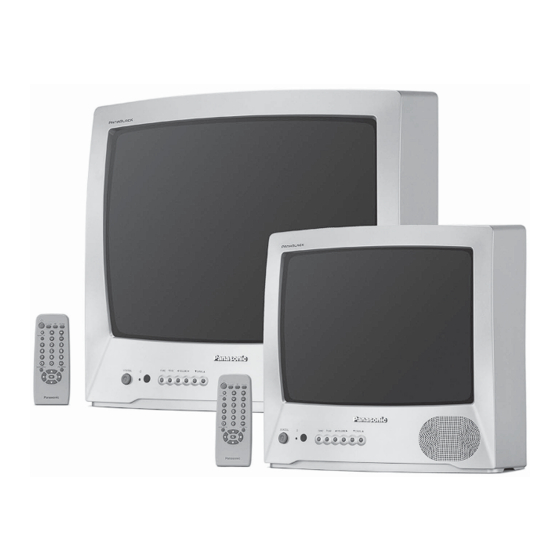
TC-14A04A
TC-20A04A
Specifications
TELEVISION
Power source
Consumption
Antenna input jack
Color systems
Tuning system
Channel capability
Picture tube (Diagonal Visual)
Audio output
Video input jack
Video Outlet
Dimension (width, height, depth)
Weight
Specifications are subject to change without notice. Weight and dimensions shown are approximate.
Remote Control Transmiter:
Power Source
Infrared Length
Number of Buttons
Dimensions (W x H x D)
Panasonic
110/220 V AC, 50/60 Hz automatic switch
75 ohms - VHF/UHF/CATV
TNQ2B2902
3V (2 AA type batteries)
9500 Å (Angstron)
29 keys
(54 x 27 x 135) mm
®
TC-14A04A
51 W
PAL-M/NTSC/PAL-N
F.S.T.
2 to 13 (VHF)
14 to 69 (UHF)
1 to125 (CATV)
Panablack 33 cm
3 W RMS
1 AV (back)
1 (back)
370 x 351 x 366 mm
9,6 kg
Order DCS - JUN2004 - 003 - MS
Color Television
TC-20A04A
110/220 V AC, 50/60 Hz automatic switch
61 W
75 ohms - VHF/UHF/CATV
PAL-M/NTSC/PAL-N
F.S.T.
2 to 13 (VHF)
14 to 69 (UHF)
1 to125 (CATV)
Panablack 48cm
3 W RMS
1AV (back)
1 (back)
502 x 455 x 471 mm
17 kg
Supplied Accessories:
• 1 Remote Control Transmitter
• 1 300Ω/75Ω Balum
• 2 "AA" (or R6) batteries (1.5V; ABNT/IEC)
• 1 Internal antenna (for TC-14A04A only)
© 2004 Panasonic da Amazônia S/A.
CS Division
Technical Support
Advertisement
Table of Contents

Related Manuals for Panasonic TC-14A04A


Summary of Contents for Panasonic TC-14A04A
-
Page 1: Service Manual
Infrared Length 9500 Å (Angstron) • 2 “AA” (or R6) batteries (1.5V; ABNT/IEC) Number of Buttons 29 keys • 1 Internal antenna (for TC-14A04A only) Dimensions (W x H x D) (54 x 27 x 135) mm Panasonic ® © 2004 Panasonic da Amazônia S/A. -
Page 2: Table Of Contents
TC-14A04A / TC-20A04A Important Safety Notice Special components are used in this television set which are important for safety. These parts are identified on the schematic diagram by the symbol . It is essential that these critical parts are replaced with the manufacturer’s specified replacement parts to prevent X-ray radiation, shock, fire or other hazards. - Page 3 TC-14A04A / TC-20A04A ABOUT LEAD FREE SOLDER (PbF) This model uses lead free solder (PbF). CAUTION: • Pb free solder has a higher melting point than standard solder; typically the melting point is 50 - 70°F (300 - 400°C) higher. Please use a high temperature soldering iron. In case of the soldering iron with temperature control,please set it to 700 ±...
-
Page 4: Operating Instructions
TC-14A04A / TC-20A04A - 4 -... -
Page 5: Ic601 - Pinout
TC-14A04A / TC-20A04A IC601 - PINOUT Symbol Description P3.1/ADC1 port 3.1 or ADC1 input P3.2/ADC2 port 3.2 or ADC2 input P3.3/ADC3 port 3.3 or ADC3 input VSSC/P digital ground for m-Controller core and periphery P0.5 port 0.5 (8 mA current sinking capability for direct drive of LEDs) P0.6/CVBSTD... -
Page 6: Ic Voltage Tables
TC-14A04A / TC-20A04A IC601 - PINOUT Symbol Description Blue output VDDA analog supply of Teletext decoder and digital supply of TV-processor (3.3 V) OTP Programming Voltage VDDC digital supply to core (3.3 V) OSCGND oscillator ground supply XTALIN crystal oscillator input... -
Page 7: Ic601 - Block Diagram
TC-14A04A / TC-20A04A IC601 - BLOCK DIAGRAM - 7 -... -
Page 8: Gp3 Chassi Feature Summary
TC-14A04A / TC-20A04A CHASSIS GP3 FEATURE SUMMARY MODELS : TC-14A04 e TC-20A04 SYSTEM : 3 systems (PAL-M/PAL-N/NTSC) (PAL-M 50hZ) POWER SOURCE : CA automatic power switching (110/220)V, 50/60Hz MEMORY : 125 positions TV TUNING RANGE : 181 channels (TV / CATV) -
Page 9: The Dac Control Functions For The Gp3 Chassis
TC-14A04A / TC-20A04A THE DAC CONTROL FOR GP3 CHASSIS FUNCTIONS AND ADJUSTMENTS HOW TO ENTER IN THE SERVICE MODE: 1- Set the “OFF TIMER” to 30 minutes. 2- Press simultaneously “RECALL” key on the remote control and VOL(-) button on the unit. -
Page 10: Adjustments
TC-14A04A / TC-20A04A ADJUSTMENTS CHK2 mode adjustments CHK2 mode table On CHK2 mode it is possible to adjust the items of the table shown here. Standard values Note: To select an item, type “4” to move forward and “3” to move back. -
Page 11: 1- Vif Detector Output Level Confirmation
TC-14A04A / TC-20A04A ADJUSTMENTS ITEM / PREPARATION PROCEDURE 1- RF AGC ADJUSTMENT ADJUSTMENT: 1. Select “RF AGC” on “CHK2” service mode. 1. Supply a color bar pattern and adjust the RF input signal 2. Adjust "RF AGC" by pressing VOL(+) or (-) until obtaining of 69 dB µV (75Ω... -
Page 12: 5- Pal Color Output Level Adjustment
TC-14A04A / TC-20A04A ADJUSTMENTS ITEM / PREPARATION PROCEDURE CALIBRATION: 5- PAL COLOR OUTPUT SIGNAL ADJUSTMENT 1. Connect the oscilloscope in TPL2 (G-OUT) with a 10KΩ 1. Supply a color bar signal and adjust the local frequency. resistor and adjust “CONTRAST”, so that the [B] waveform 2. -
Page 13: 8- Sub-Brightness And Sub-Contrast Calibration
TC-14A04A / TC-20A04A ADJUSTMENTS ITEM / PREPARATION PROCEDURE 8- SUB-BRIGHT AND SUB-CONTRAST SUB-BRIGHT CALIBRATION CALIBRATION 1. Position the color analyzer in the LOW LIGHT image area. Supply a WINDOW pattern signal 2. Ajust S-BRT <CHK 4> control, so that it is Y=0,7±0.2 for 2. -
Page 14: 11- White Quality Calibration
TC-14A04A / TC-20A04A ADJUSTMENTS ITEM / PREPARATION PROCEDURE 11- WHITE QUALITY CALIBRATION CALIBRATION: PREPARATION: 1. Adjust the magnetic field in 0.4x10⁻⁴T (400 mG), and check the white quality with the CRT turned to EAST and to WEST. 2. Receive a red pattern, adjust the COLOR control to 1. -
Page 15: 15- Vertical Deflection Calibration
TC-14A04A / TC-20A04A ADJUSTMENTS ITEM / PREPARATION PROCEDURE 14- VERTICAL DEFLECTION CALIBRATION AND S-CORR CONFIRMATION AND CALIBRATION CONFIRMATION 1) Confirmation in 50Hz 1. Adjust IMAGE to DYNAMIC NORMAL 1. Supply a PHILIPS PAL-N signal. 2. Confirm that S-CORR 50Hz is in [18] DAC. -
Page 16: Eeprom Memory Maps
TC-14A04A / TC-20A04A EEPROM MEMORY MAPS Observation: */XX : Data subjects to alterations in the calibration process (values no fixed). : Data of channels [A-M] : Corresponds to the specification of specific production of each model. : Fixed data (it doesn't alter in the calibration process) 14 &... - Page 17 TC-14A04A / TC-20A04A TABLE A2 (1XX) TABLE A4 (2XX) TABLE A6 (3XX) - 17 -...
-
Page 18: Schematics Diagrams
TC-14A04A / TC-20A04A SCHEMATIC DIAGRAMS CRT PCB SCHEMATIC DIAGRAM - 18 -... -
Page 19: Main Pcb Schematic Diagram
TC-14A04A / TC-20A04A MAIN PCB SCHEMATIC DIAGRAM SEE IC601 PINOUT TABLE BELOW IC601 PINOUT - 19 -... -
Page 20: Main Pcb Layout
TC-14A04A / TC-20A04A MAIN BOARD CIRCUIT LAYOUT - 20 -... -
Page 21: Signal Waveforms
TC-14A04A / TC-20A04A SIGNAL WAVEFORM • All waveforms were obtained using 127V 50Hz power source and Color Bars Pattern. IC451 Pin 1 Pin 5 Pin 7 IC601 Pin 16 Pin 17 - 21 -... - Page 22 TC-14A04A / TC-20A04A IC601 Pin 18 Pin 19 Pin 38 Pin 40 Pin 42 Pin 55 - 22 -...
- Page 23 TC-14A04A / TC-20A04A IC601 Pin 56 Pin 57 Pin 58 Pin 63 Pin 64 - 23 -...
- Page 24 TC-14A04A / TC-20A04A IC804 Q551 Pin 1 Collector Q501 Base Collector Q601 Q602 Emiter Collector - 24 -...
-
Page 25: Exploded View
TC-14A04A / TC-20A04A EXPLODED VIEW - 25 -... -
Page 26: Replacement Mechanical Parts List
TC-14A04A / TC-20A04A REPLACEMENT MECHANICAL PARTS LIST Ref. No. TC-14A04A Part No. TC-20A04A Part No. Part Name & Description EASZ9D05B8 EASZ9D05B8 FULL RANGE SPEAKER TSA8108-6KP - - - - O - - - - TELESCOPIC ANTENNA S-U5012 S-U5012 300W ADAPTOR BALLUM... -
Page 27: Replacement Electrical Parts List
TC-14A04A / TC-20A04A REPLACEMENT ELECTRICAL PARTS LIST TC-14A04A TC-20A04A Ref. No. Part No. Part No. Part Name & Description MAIN BOARD MAIN PAL14A04MON PAL20A04MON A + L ASSEMBLED PCB CAPACITORS C001 ECEA1CKA220B ECEA1CKA220B RADIAL POLAR ELECTROLYTICAL CAPACITOR 22,00 µF 16V... - Page 28 TC-14A04A / TC-20A04A TC-14A04A TC-20A04A Ref. No. Part No. Part No. Part Name & Description C605 ECQV1H224JL3 ECQV1H224JL3 RADIAL POLYESTER FILM CAPACITOR 220,00 nF 50V 5,0 % C606 ECJ2VC1H222J ECJ2VC1H222J SMD CAPACITOR 2.200,00 PF 50V 5,0 % NPO C607 ECEA1HKA010B ECEA1HKA010B RADIAL POLAR ELECTROLYTICAL CAPACITOR 1,00 µF 50V...
- Page 29 TC-14A04A / TC-20A04A TC-14A04A TC-20A04A Ref. No. Part No. Part No. Part Name & Description C879 ECQV1H104JL3 ECQV1H104JL3 RADIAL POLYESTER FILM CAPACITOR 100,00 nF 50V 5,0 % C880 F2A1C1020049 F2A1C1020049 RADIAL POLAR ELECTROLYTICAL CAPACITOR 1.000,00 µF 16V C881 F2A1C101A180 F2A1C101A180 RADIAL POLAR ELECTROLYTICAL CAPACITOR 100,00 µF 16V...
- Page 30 TC-14A04A / TC-20A04A TC-14A04A TC-20A04A Ref. No. Part No. Part No. Part Name & Description D630 MAZ30560HL MAZ30560HL ZENER DIODE SMD 5,8 V 0,2 W 5mA VZ=5,66 ~ 5,95 V @ IZ=5MA D801 ERZV10V621CS ERZV10V621CS VARISTOR D803 B0EBNT000002 B0EBNT000002 AXIAL RECTIFIER DIODE 800V 4,0 A...
- Page 31 TC-14A04A / TC-20A04A TC-14A04A TC-20A04A Ref. No. Part No. Part No. Part Name & Description L501 - - - - - - O - - - - - - ELH5L4101Z LINEARITY COIL L502 EXCELSA35T EXCELSA35T AXIAL BEAD CORE L510 EXCELSA35T...
- Page 32 TC-14A04A / TC-20A04A TC-14A04A TC-20A04A Ref. No. Part No. Part No. Part Name & Description R190 ERJ6GEYJ391V ERJ6GEYJ391V SMD RESISTOR 390,00 Ohm 1/8 W 5,0 % R351 ERJ6ENF1001V ERJ6ENF1001V SMD RESISTOR 1,00 kOhm 1/10 W 1,0 % R352 ERJ6ENF1001V ERJ6ENF1001V...
- Page 33 TC-14A04A / TC-20A04A TC-14A04A TC-20A04A Ref. No. Part No. Part No. Part Name & Description R587 ERJ6GEYJ823V ERJ6GEYJ823V SMD RESISTOR 82,00 kOhm 1/8 W 5,0 % R588 ERJ6GEYJ104V ERJ6GEYJ104V SMD RESISTOR 100,00 kOhm 1/8 W 5,0 % R589 ERJ6GEYJ103V ERJ6GEYJ103V...
- Page 34 TC-14A04A / TC-20A04A TC-14A04A TC-20A04A Ref. No. Part No. Part No. Part Name & Description R1019 ERJ6ENF4421V ERJ6ENF4421V SMD RESISTOR 4,42 kOhm 1/10 W 1,0 % R1020 ERJ6ENF7501V ERJ6ENF7501V SMD RESISTOR 7,50 kOhm 1/10 W 1,0 % R1021 ERJ6ENF1871V ERJ6ENF1871V...
- Page 35 TC-14A04A / TC-20A04A TC-14A04A TC-20A04A Ref. No. Part No. Part No. Part Name & Description OTHERS TXAJTFFCB14A12 TXAJTFFCB14A12 FLEXIBLE JUMPER W/ TERMINAL F801 K5D402BK0004 K5D402BK0004 FUSE 4A 250V F801-L K3GD9BB00001 K3GD9BB00001 FUSE SUPPORT F801-R K3GD9BB00001 K3GD9BB00001 FUSE SUPPORT SPR451 TESA031...
- Page 36 Panasonic da Amazônia S.A. CS DIVISION - TECHNICAL SUPPORT Rod. Presidente Dutra, Km 155 São José dos Campos - SP...
Need help?
Do you have a question about the TC-14A04A and is the answer not in the manual?
Questions and answers