Table of Contents
Advertisement
Advertisement
Table of Contents
Troubleshooting

Related Manuals for OleumTech WG-0900-DH1


Summary of Contents for OleumTech WG-0900-DH1
-
Page 1: User Guide
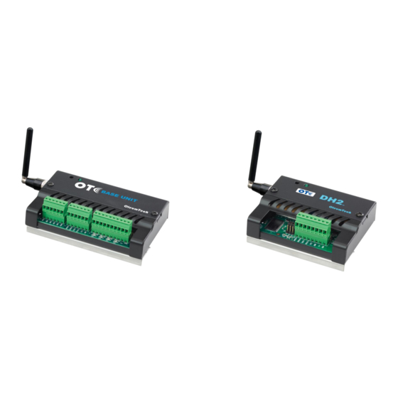
DH1 BASE UNIT / DH2 WIRELESS GATEWAY USER GUIDE User Guide DH1 BASE UNIT WIRELESS GATEWAY WG-0900-DH1/ WG-0915-DH1 WG-2400-DH1/WG-2410-DH1 WG-0868-DH1 DH2 WIRELESS GATEWAY WG-0900-DH2/ WG-0915-DH2 WG-2400-DH2/WG-2410-DH2 WG-0868-DH2 Page 1 Controlled Copy... -
Page 2: Table Of Contents
DH1 BASE UNIT / DH2 WIRELESS GATEWAY USER GUIDE MODBUS WRITE FUNCTION AND WRITING TO GATEWAY ......47 Contents (Index on Next Page) PEER-TO-PEER/REPEATER/SHARING DATA ..........49 Contents (Index on Next Page) ................... 2 MAPPING AN IMPORT TO AN OUTPUT ON DH1 BASE UNIT ......51 PREFACE/SAFETY ...................... - Page 3 DH1 BASE UNIT / DH2 WIRELESS GATEWAY USER GUIDE PRODUCT & SYSTEM OVERVIEW ................7 Index RETRIEVING PROJECT FILE FROM GATEWAY ............65 ADDING IMPORT POINTS TO MODBUS TABLE ............33 REVISION HISTORY ....................76 BreeZ® MAIN SCREEN VIEW ..................29 RF REFRESH TIME TAG(S) ..................
-
Page 4: Preface/Safety
DH1 BASE UNIT / DH2 WIRELESS GATEWAY USER GUIDE PREFACE/SAFETY Thank you for choosing the DH1 Base Unit/DH2 Wireless Gateway by OleumTech™. WARNING: EXPLOSION HAZARD – Do not use USB connectors in hazardous area. AVERTISSEMENT: RISQUE D'EXPLOSION - Ne pas utiliser les connecteurs USB en This document describes the hardware components and how to install and operate zone dangereuse. -
Page 5: Compliances/Conformité
DH1 BASE UNIT / DH2 WIRELESS GATEWAY USER GUIDE FCC Compliance Statement 1. COMPLIANCES/CONFORMITÉ This equipment has been tested and found to comply with the limits for a class B digital device, pursuant to Part 15 of the FCC Rules. These limits are designed to provide reasonable English protection against harmful interference in a residential installation. -
Page 6: Certifications
DH1 BASE UNIT / DH2 WIRELESS GATEWAY USER GUIDE Réorienter ou déplacer l'antenne. CONFORMITÉ Augmenter la distance entre l'équipement et le récepteur. Consultez le fabricant de l'aide technique. Françias Cet équipement a été certifié conforme aux limites d'un dispositif informatique de classe B, conformément aux règles de la FCC. -
Page 7: Product & System Overview
DH1 BASE UNIT / DH2 WIRELESS GATEWAY USER GUIDE 3. PRODUCT & SYSTEM OVERVIEW SHARED PRODUCT HIGHLIGHTS - Serves as a Primary Data Collection Point in OleumTech™ Wireless Sensor and I/O Network - Advanced Networking Architecture: Point-to-Multipoint/Star (Gateway-to-End Nodes) & Peer-to-Peer/Repeater... -
Page 8: Controlled Copy
USER GUIDE OLEUMTECH WIRELESS SENSOR NETWORK ADVANCED NETWORKING ARCHITECTURE Reliable, Robust Wireless Performance The DH1 Base Unit or DH2 Wireless Gateway plays a vital role in the OleumTech Wireless Eliminates Costly Conduits and Wiring Monitor/Control Process Conditions 24/7 Sensor Network. -
Page 9: Hardware Overview
DH1 BASE UNIT / DH2 WIRELESS GATEWAY USER GUIDE 4. HARDWARE OVERVIEW Page 9 Controlled Copy... -
Page 10: Items Required For Setup
Screwdriver Set including Technician’s Screwdriver, Adjustable Wrench Any Other Tools Depending on Site and Equipment OleumTech Wireless Transmitter(s) OleumTech Wireless Gateway(s) (DH1 Base Unit or DH2) OleumTech Wireless I/O Modules Internet Access OleumTech RS485 I/O Expansion System ... -
Page 11: Configuration/Installation Sequence
1. Install Gateway inside a NEMA enclosure 1. Download and install latest BreeZ® Software v5.0 or higher to a PC 2. Follow best grounding practices Download Center: http://support.oleumtech.com (requires login credentials) 3. Setup and connect an Antenna with Lightening Arrestor to Gateway 2. -
Page 12: Led States (Status Indicators)
DH1 BASE UNIT / DH2 WIRELESS GATEWAY USER GUIDE 7. LED STATES (STATUS INDICATORS) State Green LED Booting up Long blink + 5 short blinks Device On or Off Connected to PC / Updating in Progress / Solid green Firmware Upgrade Device updated/programmed Long blink + 5 short blinks Device Failure... -
Page 13: Wiring Diagrams (Serial And Power)
DH1 BASE UNIT / DH2 WIRELESS GATEWAY USER GUIDE 8. WIRING DIAGRAMS (SERIAL AND POWER) Please use the following wiring diagrams and jumper settings to connect a third-party device to the Wireless Gateway. 1. SERIAL/RTU Port (DH1 Base Unit) a. DH1 Base Unit – RS232 Field Wiring and Jumper Settings c. -
Page 14: Controlled Copy
DH1 BASE UNIT / DH2 WIRELESS GATEWAY USER GUIDE 2. SERIAL/RTU Port (DH2) a. DH2 – RS232 Field Wiring and Jumper Settings c. DH2 – RS485 Full Duplex Wiring and Jumper Settings b. DH2 – RS485 Half Duplex Wiring and Jumper Settings Page 14 Controlled Copy... -
Page 15: Controlled Copy
DH1 BASE UNIT / DH2 WIRELESS GATEWAY USER GUIDE 3. DH1 Base Unit RS485 Port 4. Config Port Pin 1 Pin 1 Pin Name Generic Modbus Device Pin 1 Reserved RX− TX− TX− RX− Reserved Pin Name PC Configuration Cable DB9 (Pin Number) Reserved ... -
Page 16: Grounding Best Practices
2. Le boîtier du panneau doit être mis à la terre . 2. The panel enclosure must be grounded to earth. 3. Il est sûr de monter OleumTech Wireless Gateways au boîtier du panneau depuis le châssis et les terminaux / sol de puissance numériques sont 3. -
Page 17: Controlled Copy
DH1 BASE UNIT / DH2 WIRELESS GATEWAY USER GUIDE Terre passerelles et modules E / S: (Français) Grounding Gateways & I/O Modules: Négative batterie ne doit jamais être commun avec la terre. Pour les enveloppes en fibre de verre, le fond de panier à l'intérieur peut ... -
Page 18: Installation
DH1 BASE UNIT / DH2 WIRELESS GATEWAY USER GUIDE 10. INSTALLATION INSTALLATION (FRANÇAIS) The following procedure describes how to install a Gateway inside a NEMA 4X- La procédure suivante décrit l'installation correcte d'un Gateway. type enclosure (or an enclosure with a minimum IP 54 rating and that complies Avant d'effectuer cette procédure, se assurer que le Gateway répond aux... -
Page 19: Controlled Copy
DH1 BASE UNIT / DH2 WIRELESS GATEWAY USER GUIDE 1. Mount Gateway onto DIN Rail Inside of an Enclosure 2. Drilling a Hole on the Bottom of Enclosure for Routing Antenna Remove top cover on Gateway held by 2 screws, then loosen the Cable May Be Required (5/16”... -
Page 20: Controlled Copy
DH1 BASE UNIT / DH2 WIRELESS GATEWAY USER GUIDE Do not install other antenna on the same vertical plane – provide 4. Connect External Power sufficient vertical separation (Ne installez pas autre antenne sur le même Gateway accepts 9-30 VDC, 12 V recommended (Use 18-24 gauge plan vertical - assurer la séparation verticale suffisante.) wires) *(DH2: 9-24 VDC Prior to SN: SM11266715) -
Page 21: Rf Setup
Wireless Sensor Network that involves a Gateway and a level (tested for point-to-point values only). Actual wireless RF range may vary depending on handful of End Nodes, please consult with an OleumTech Application Engineer or a location, antenna and cable setup, and line of sight. -
Page 22: Controlled Copy
Site Authentication (5) Save project file OleumTech Wireless Sensor and I/O Network also provides users to ability (6) Upgrade all wireless device firmware to version that supports AES to enable Site Authentication. This method further extends security (7) Update all wireless devices in the project file measures and eliminate or minimize cross-talk with neighboring networks. -
Page 23: Breez® Project File Creation
Wireless Gateway Select File Location by clicking Browse button BreeZ® Software Download http://support.oleumtech.com BreeZ® Software Compatibility Matrix: http://goo.gl/KzsY01 1. Open BreeZ® Software from Your PC a. BreeZ® v5.x can open Project Files that are v3.3.0.109 or higher b. BreeZ® v5.x Project File cannot be opened using v4.x or v3.x When opening Project File created using a previous version, BreeZ®... -
Page 24: Controlled Copy
DH1 BASE UNIT / DH2 WIRELESS GATEWAY USER GUIDE 4. RF Settings 5. Configure Primary Wireless Gateway / RTU Port 1 Settings Create Gateway Name Select Frequency that matches the Radio Frequency (RF) of the wireless devices Select Gateway Type: DH1 Base Unit or DH2 Select Channel to avoid any RF conflict with any nearby sites... -
Page 25: Controlled Copy
DH1 BASE UNIT / DH2 WIRELESS GATEWAY USER GUIDE 6. Add Transmitter (WT Series RTD as Example Used) 7. Configure Transmitter Create Transmitter Name Enter Transmit Interval in Hour:Minute:Second Series – Select WT Series – LCD Select 16-bit 32-bit Modbus Mapping Table Transmitter: Select RTD i. -
Page 26: Controlled Copy
DH1 BASE UNIT / DH2 WIRELESS GATEWAY USER GUIDE NOTE: Once a new Battery Pack is installed, it is perfectly normal to get a reading of 3.2 to 3.3 V. This is due to the fact that the WT Series Transmitters take battery level while it is under load, providing a reliable method of monitoring battery health. -
Page 27: Controlled Copy
DH1 BASE UNIT / DH2 WIRELESS GATEWAY USER GUIDE 8. Select RTD Wire Type 9. Confirm Transmitter Addition Select RTD wiring mode that matches the Sensor (2, 3 or 4) Verify the added Transmitter in the Device Table 4-wire type is factory default for Direct Mount version “RT1” Click Finish Click... -
Page 28: Controlled Copy
DH1 BASE UNIT / DH2 WIRELESS GATEWAY USER GUIDE 10. Verify Project File To add another Transmitter or I/O Module, i. Click on the Gateway in the Project Tree ii. Click (Insert) button iii. Select desired device To add another Gateway, i. -
Page 29: Breez® Main Screen View
DH1 BASE UNIT / DH2 WIRELESS GATEWAY USER GUIDE 13. BreeZ® MAIN SCREEN VIEW Page 29 Controlled Copy... -
Page 30: Modbus Mapping Table Management
DH1 BASE UNIT / DH2 WIRELESS GATEWAY USER GUIDE 4. Export Modbus Mapping Table to View Outside of BreeZ® 14. MODBUS MAPPING TABLE MANAGEMENT 1. Double-click on Gateway in the Project Tree Click on File menu Select “Export to .CSV…” 2. -
Page 31: Controlled Copy
DH1 BASE UNIT / DH2 WIRELESS GATEWAY USER GUIDE 5. How to Add a Register from a Device Select a tag(s) from “Exportable Tags” box Single-click on an end node in project tree Click on “E” Edit button Use the left arrow to move it over to “Exported Tags” box Click OK when finished Page 31 Controlled Copy... -
Page 32: Controlled Copy
DH1 BASE UNIT / DH2 WIRELESS GATEWAY USER GUIDE Double-click Gateway in project tree Click on Modbus tab to verify added register Option: use the mouse to click and drag to desired position Click on Imports tab 16-bit register starting point can be changed in BreeZ® (Range: 0-3001) i. -
Page 33: Adding Import Points To Modbus Table
DH1 BASE UNIT / DH2 WIRELESS GATEWAY USER GUIDE 4. Right-click over highlighted area and select paste to integer or float 15. ADDING IMPORT POINTS TO MODBUS TABLE table Any item contained in Gateway’s Import tab can be exported or added to Gateway’s Modbus Mapping table so that those points can be monitored by a Modbus Master device. -
Page 34: Controlled Copy
DH1 BASE UNIT / DH2 WIRELESS GATEWAY USER GUIDE 6. Double-click on Gateway in the Project Tree 9. Export Modbus Mapping Table to View Outside of BreeZ® 7. Click on Modbus Tab Click on File menu Select “Export to .CSV…” Exported file gets saved automatically to the same directory as the Project File 8. -
Page 35: Editing Gateway Properties
DH1 BASE UNIT / DH2 WIRELESS GATEWAY USER GUIDE 3. Serial/RTU Port Tab 16. EDITING GATEWAY PROPERTIES Allows configurations of Serial/RTU port RTU port can be set as a Modbus Master, Modbus Slave, After making any changes, must update Gateway for changes to LevelMaster ASCII Slave, or ROC-Link Master take into effect. -
Page 36: Controlled Copy
DH1 BASE UNIT / DH2 WIRELESS GATEWAY USER GUIDE 4. RS485 Port Tab 6. Analog Inputs Tab (DH1 Base Unit only) Allows configurations of RS485 port Interval: edit read interval Port can be set as a Modbus Master, Modbus Slave, or LevelMaster ASCII Slave Use the appropriate port settings to match with connecting device Double-click on input to edit parameters... -
Page 37: Controlled Copy
DH1 BASE UNIT / DH2 WIRELESS GATEWAY USER GUIDE 7. Discrete Inputs Tab (DH1 Base Unit only) 8. Discrete Outputs Tab (DH1 Base Unit only) Name: edit name Name: edit name Mode: Options: Normally open Initially on Normally closed Normally closed Count high Pulsed (stays on for specified duration of time in ms) Count low... -
Page 38: Com Port Setup On Pc And Breez
DH1 BASE UNIT / DH2 WIRELESS GATEWAY USER GUIDE 17. COM PORT SETUP ON PC AND BreeZ® v. Identify COM Port ID For programming devices such as DH2, DH1 Base Unit, Wireless Transmitters, or Wireless I/O Modules, the PC’s COM Port must be configured for use. -
Page 39: Controlled Copy
DH1 BASE UNIT / DH2 WIRELESS GATEWAY USER GUIDE Select COM Port ID that matches what you found in Device Manager vi. Use dropdown box to select COM Port DO NOT CHANGE THE BAUD RATE! vii. This baud rate setting is for your PC COM Port viii. -
Page 40: Gateway Update (Firmware Upgrade)
DH1 BASE UNIT / DH2 WIRELESS GATEWAY USER GUIDE Click Flash button to begin the update Firmware process 18. GATEWAY UPDATE (FIRMWARE UPGRADE) 1. Connect Power to Gateway (9-30 V) *(DH2: 9-24 VDC Prior to SN: SM11266715) 2. Connect Gateway to PC Connect USB to Serial Adapter to PC (USB) -
Page 41: Connect To Gateway Function In Breez
DH1 BASE UNIT / DH2 WIRELESS GATEWAY USER GUIDE 3. Device Tab 19. CONNECT TO GATEWAY FUNCTION IN BreeZ® Displays how the device is set up Displays Firmware version When a Gateway is connected to BreeZ® Software, users can also directly access the settings stored on the device. -
Page 42: Controlled Copy
DH1 BASE UNIT / DH2 WIRELESS GATEWAY USER GUIDE 5. Config Port Tab Displays how the Config port is set up for connecting to PC Page 42 Controlled Copy... -
Page 43: Transmitter Update - Cable Method (Program / Configure)
DH1 BASE UNIT / DH2 WIRELESS GATEWAY USER GUIDE 20. TRANSMITTER UPDATE – CABLE METHOD (PROGRAM / CONFIGURE) 3. Update/Upload Transmitter Using BreeZ® Project File Click on Transmitter in the Project Tree Click (Update Device) button 1. Remove Enclosure Cover from Transmitter (Be Sure Battery Pack Is Connected to Puck or PC Board) 2. -
Page 44: Polling Modbus Registers Using Breez
DH1 BASE UNIT / DH2 WIRELESS GATEWAY USER GUIDE 6. Verify the Gateway is in Modbus Slave Mode 21. POLLING MODBUS REGISTERS USING BreeZ® BreeZ® Software version 4.0 and higher provides users the ability to poll Modbus registers from a Wireless Gateway for installation verification. This feature allows users to take poll once per command. -
Page 45: Debug Mode
DH1 BASE UNIT / DH2 WIRELESS GATEWAY USER GUIDE 11. Right-Click over Highlighted Area and Select Poll Modbus Register(s) 22. DEBUG MODE BreeZ® Software allows users to view debug information from Gateway for advanced diagnostic verification. To use this mode, the Gateway must be set up in Debug mode. Modbus polling or writing feature using BreeZ®... -
Page 46: Rf Refresh Time Tag(S)
DH1 BASE UNIT / DH2 WIRELESS GATEWAY USER GUIDE 23. RF REFRESH TIME TAG(S) Adding a RF Refresh Time tag to any Modbus point ensures the data that is held in the Modbus table is valid. When the RF Refresh tag is used for trending, a normal graph will look like a sawtooth. -
Page 47: Modbus Write Function And Writing To Gateway
GATEWAY In order to relay data from a third-party Modbus Master device to a point or output in an OleumTech network, a Modbus Write function must be created in primary Gateway’s Modbus table. Once the function is created, 3. Right-click inside Modbus window and select “New Write Import”... - Page 48 DH1 BASE UNIT / DH2 WIRELESS GATEWAY USER GUIDE 5. Point will be added to Modbus table 8. Poll Modbus register to view value status 6. Save project file and MUST update Gateway 7. Write a value from a Modbus Master device Values must be written as either 16 or 32-bit holding register Page 48 Controlled Copy...
-
Page 49: Peer-To-Peer/Repeater/Sharing Data
3. Select a point or points from Import tab from Gateway (origin) to 25. PEER-TO-PEER/REPEATER/SHARING DATA share with another Gateway OleumTech Wireless Sensor Network is extremely flexible by allowing any tags to be shared across multiple Wireless Gateways in a single networking system. Peering allows for more efficient and powerful networking. - Page 50 DH1 BASE UNIT / DH2 WIRELESS GATEWAY USER GUIDE 6. Check map to integer or float point table or both 9. The point(s) is automatically mapped to its Modbus register holding table on DH1 Base Unit or secondary Gateway 10. Using shared point based on interval or on change Double-click primary Gateway b.
-
Page 51: Mapping An Import To An Output On Dh1 Base Unit
DH1 BASE UNIT / DH2 WIRELESS GATEWAY USER GUIDE 3. Double-click on a DH1 Base Unit in project tree 26. MAPPING AN IMPORT TO AN OUTPUT ON DH1 BASE UNIT With the Wireless Gateway, any import point can be mapped to an available output in the same network whether it be to a DH1 Base Unit, Wireless Multi-I/O Module, or another device with an output. -
Page 52: Mapping An Import To An Output On Wireless Multi-I/O Module
DH1 BASE UNIT / DH2 WIRELESS GATEWAY USER GUIDE 2. Click on Gateway in project file and use + button to add a Wireless 27. MAPPING AN IMPORT TO AN OUTPUT ON Multi-I/O Module to the system WIRELESS MULTI-I/O MODULE Any import point on a Gatewway can be mapped to an available output in the same network whether it be to a DH1 Base Unit, Wireless Multi-I/O Module, or another device with outputs. - Page 53 DH1 BASE UNIT / DH2 WIRELESS GATEWAY USER GUIDE 4. Double-click on Gateway in project tree 9. Right-click over desired output target and select paste output source 5. Click on Imports tab 6. Select desired point to be mapped to an output 10.
-
Page 54: Rs485 I/O Expansion System With Gateway
28. RS485 I/O EXPANSION SYSTEM WITH GATEWAY 2. Open a BreeZ® project file Users can add local I/O points by deploying the OleumTech RS485 I/O 3. Access Gateway’s properties by clicking “E” button or right-clicking Expansion System to a Gateway. - Page 55 DH1 BASE UNIT / DH2 WIRELESS GATEWAY USER GUIDE 6. Click on Gateway in project tree and click + Add Device button and 7. Under IO Bus tab, select desired RTU port or RS485 port select “Modbus Module” If using RTU port, set Slave ID = I/O Module ID on rotary switch dial + 1 Page 55 Controlled Copy...
- Page 56 DH1 BASE UNIT / DH2 WIRELESS GATEWAY USER GUIDE 8. Click Modbus Inputs tab and configure input settings 10. How to map inputs reads to Gateway’s Modbus register holding table Refer to Modbus Mapping table Double-click on Gateway in the Project Tree Click on “Imports”...
- Page 57 DH1 BASE UNIT / DH2 WIRELESS GATEWAY USER GUIDE 11. How to write to outputs using third-party Modbus Master device Select “Imports” tab and right-click on the newly created “Write” command and select “Copy” Double-click on Gateway in the Project Tree Select “Modbus”...
-
Page 58: Modbus Master Function
DH1 BASE UNIT / DH2 WIRELESS GATEWAY USER GUIDE 1. Determine if using RTU or RS485 port 29. MODBUS MASTER FUNCTION 2. Open a BreeZ® project file Gateway’s Serial/RTU port and DH1 Base Unit’s RS485 port can be used to set it as a Modbus Master device. - Page 59 DH1 BASE UNIT / DH2 WIRELESS GATEWAY USER GUIDE 5. RS485 port method (DH1 Base Unit only) 6. Click on Gateway in project tree and click + Add Device button and select “Modbus Module” Click on RS485 port tab Select Modbus Master for Mode of Operation Configure rest of settings Page 59 Controlled Copy...
- Page 60 DH1 BASE UNIT / DH2 WIRELESS GATEWAY USER GUIDE 7. Under IO Bus tab, select RTU or Ethernet port 9. Click Modbus Outputs tab and configure output settings Select RTU or RS485 port, and select Slave ID Configure output settings 8.
- Page 61 DH1 BASE UNIT / DH2 WIRELESS GATEWAY USER GUIDE 11. How to write to outputs using third-party Modbus Master device Select “Imports” tab and right-click on the newly created “Write” command and select “Copy” Double-click on Gateway in the Project Tree Select “Modbus”...
-
Page 62: Roc Link Master
DH1 BASE UNIT / DH2 WIRELESS GATEWAY USER GUIDE 2. Insert ROC Link Module for Gateway 30. ROC LINK MASTER Gateway can be configured as a ROC Link Master through the Serial/RTU. It supports two Opcodes Opcode 17: login request Opcode 10: read configurable opcode data Allows user to read up to 10 user configurable (TLP) points from a ROC. - Page 63 DH1 BASE UNIT / DH2 WIRELESS GATEWAY USER GUIDE 3. Configure ROC Link Module 5. Configure Points Enter ROC information and Security if needed 6. Verify ROC Module Added in Project Tree Once Configuration is 4. Set Read Interval and Click Add Button to Add Points (supports up to Complete 10 points) 7.
-
Page 64: Saving Project File To Gateway
DH1 BASE UNIT / DH2 WIRELESS GATEWAY USER GUIDE 4. Select Desired Project File from PC or Another Drive Source and 31. SAVING PROJECT FILE TO GATEWAY Click OK BreeZ® Software version 4.0 and higher allows users to save the Project File onto any Wireless Gateway (also requires Gateway Firmware version 1.3.0.93 or higher). -
Page 65: Retrieving Project File From Gateway
DH1 BASE UNIT / DH2 WIRELESS GATEWAY USER GUIDE 5. Select a Location to Save the Retrieved File 32. RETRIEVING PROJECT FILE FROM GATEWAY 1. Connect Gateway to PC Using Proper Cables 2. Open BreeZ® Software 3. Close Project Creation Wizard Gateway power input spec to 9-30 VDC 6. -
Page 66: Wireless Site Security Key
DH1 BASE UNIT / DH2 WIRELESS GATEWAY USER GUIDE File Saving Behavior in Relations to Site Security 33. WIRELESS SITE SECURITY KEY Key will change when: i. Saving a new project file in BreeZ® 1. Default: When creating a new project file in BreeZ®, Site Security is ii. - Page 67 DH1 BASE UNIT / DH2 WIRELESS GATEWAY USER GUIDE 3. What To Do When Key is Lost Double-click on “Site” in the project tree and verify key change If a key is lost or switched accidentally to an existing project file, the key can be retrieved from the Gateway Connect Gateway to PC Double-click on “Gateway”...
-
Page 68: Troubleshooting - Gateway
(see BreeZ® Configuration Software User Guide). 2. DH1 Base Unit or DH2 Not Communicating with a Device If the DH1 Base Unit or DH2 is not communicating with another OleumTech Transmitter: 6. Resetting the DH1 Base Unit or DH2 ... -
Page 69: Troubleshooting - Transmitter
DH1 BASE UNIT / DH2 WIRELESS GATEWAY USER GUIDE 35. TROUBLESHOOTING – TRANSMITTER 1. Radio / Antenna Symptom: Action/Resolution: Confirm that Antenna has a clear line of sight to all devices. Reset the device. Site Security Key may not match Gateway and other devices. Update Site Security and update all devices with the No communication with Wireless Gateway same Project File. - Page 70 DH1 BASE UNIT / DH2 WIRELESS GATEWAY USER GUIDE 2. Hardware Connection Symptom: Action/Resolution: Verify the Battery Pack is securely connected to the device. Verify Configuration Cable is securely connected to the device and PC. Device cannot communicate with BreeZ® ...
- Page 71 DH1 BASE UNIT / DH2 WIRELESS GATEWAY USER GUIDE 3. Configuration Symptom: Action/Resolution: Update all devices with the same Project File. Confirm Antennas has a clear line of sight to all devices and are within approved distances. Change the site Channel ID and update all devices.
-
Page 72: General Maintenance
COM Port - a serial communication physical interface through which information transfers in or out one bit at a time. Configuration Port - the COM Port used to configure an OleumTech device. Page 72 Controlled Copy... - Page 73 EFM - Electronic Flow Meter. communication between many devices connected to the same network. End Node - OleumTech network device that monitors process conditions. Modbus Master - A device that polls (requests and sends) information from one or more Slave devices in a Modbus network.
- Page 74 DH1 BASE UNIT / DH2 WIRELESS GATEWAY USER GUIDE Modbus Module - Used when a port on a receiver is set to Modbus Master mode. Used to read and RAW Units - Digital representation of an analog signal. write values to a Modbus Slave device. Refresh Time - Count that increases every one (1) second.
-
Page 75: Warranty (Limited)
OleumTech warrants that goods repaired by it pursuant to the warranty are free from Trending – recording of data based on a set interval. -
Page 76: Revision History
Renamed Base Unit to DH1 Base Unit Added major factors to actual peer-to-peer capabilities in section 25 OleumTech has made a good faith effort to ensure the accuracy of the information in this document and disclaims the implied warranties of...
Need help?
Do you have a question about the WG-0900-DH1 and is the answer not in the manual?
Questions and answers